 The KA1RCI Repeater Network
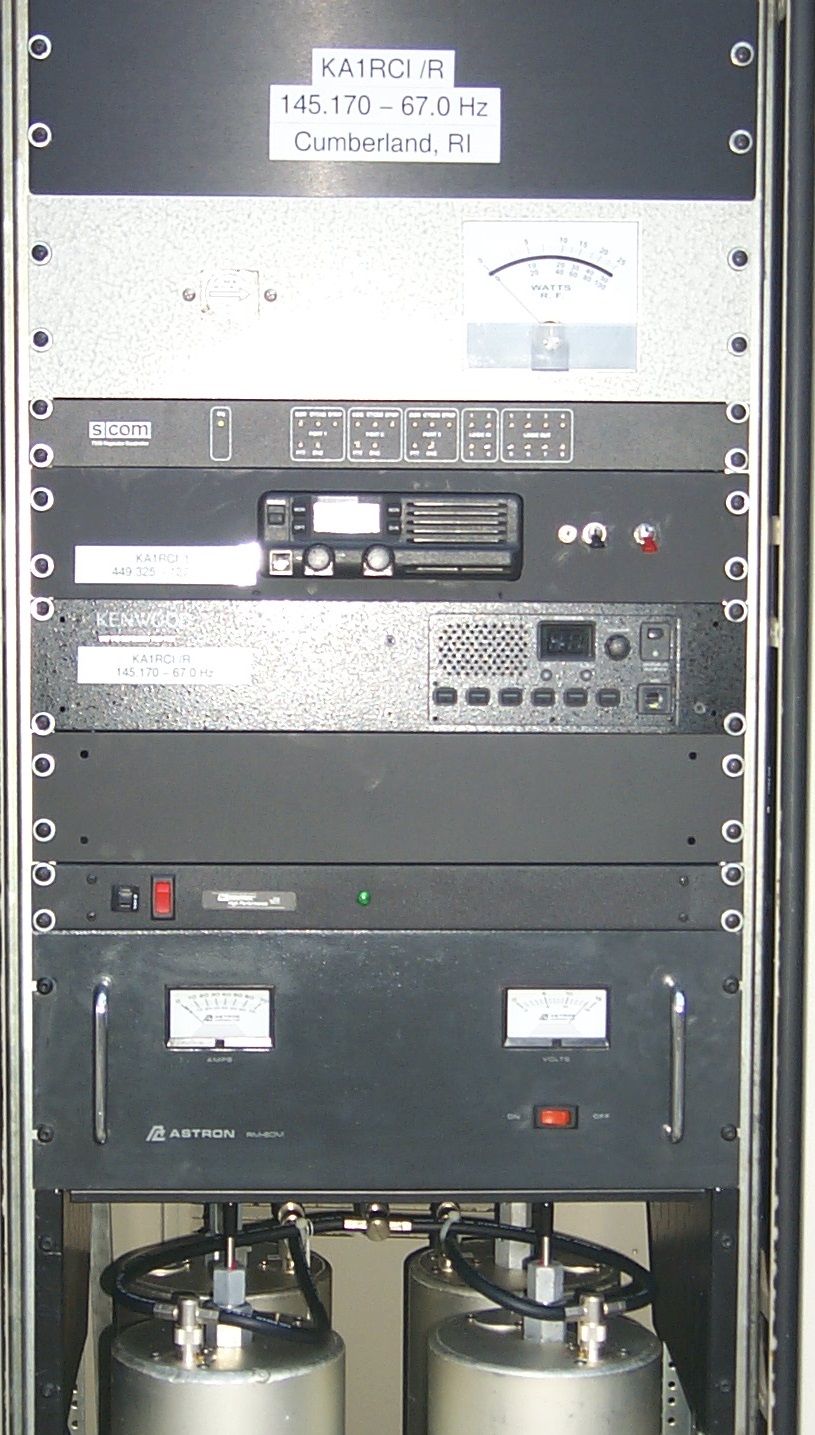
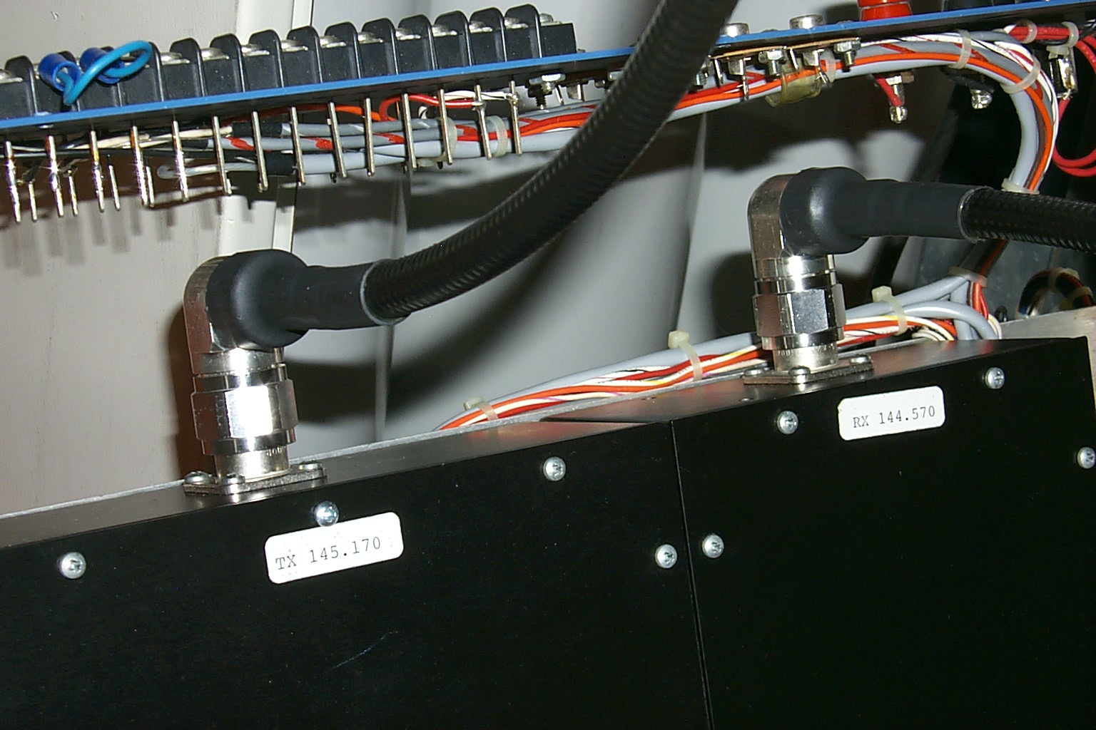
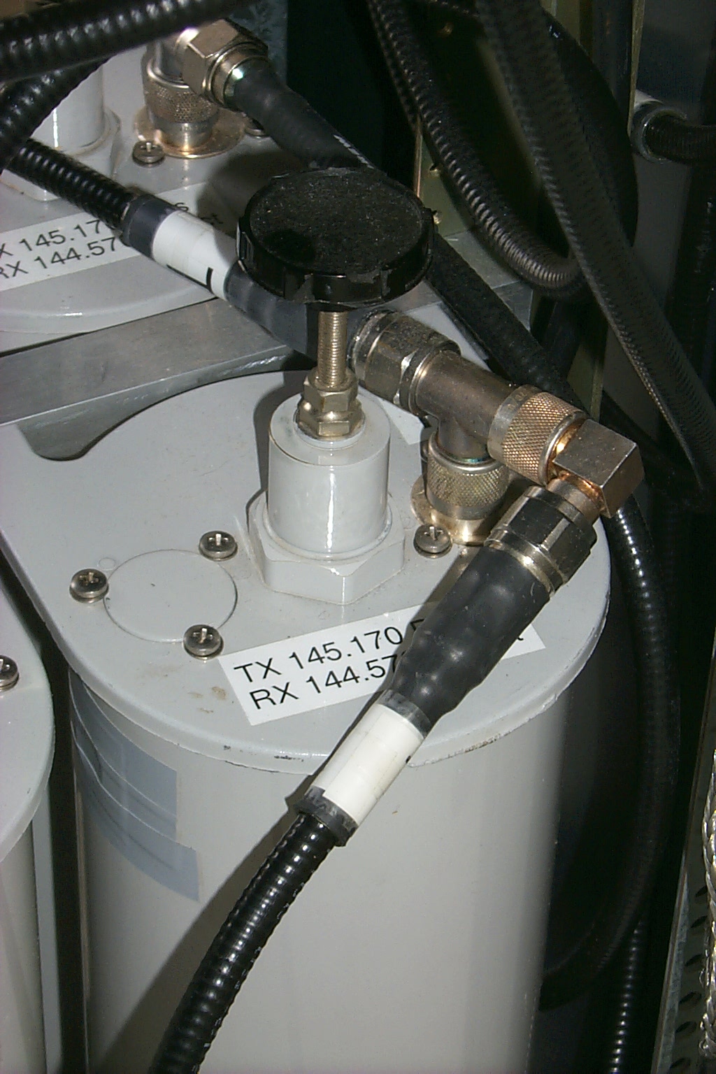
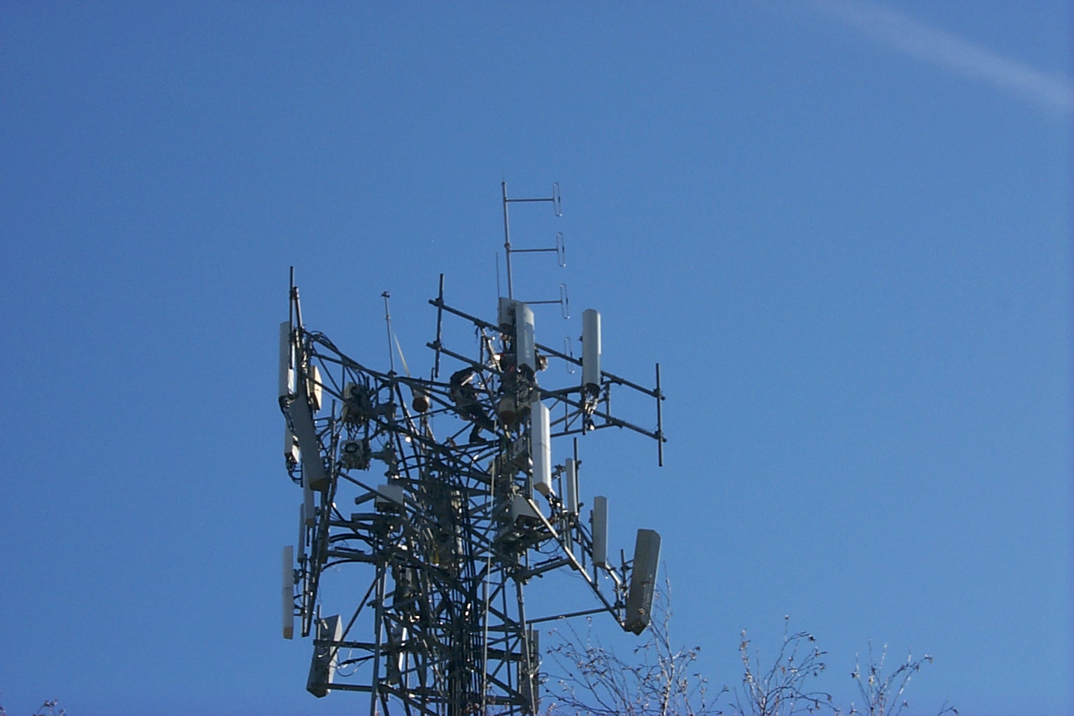
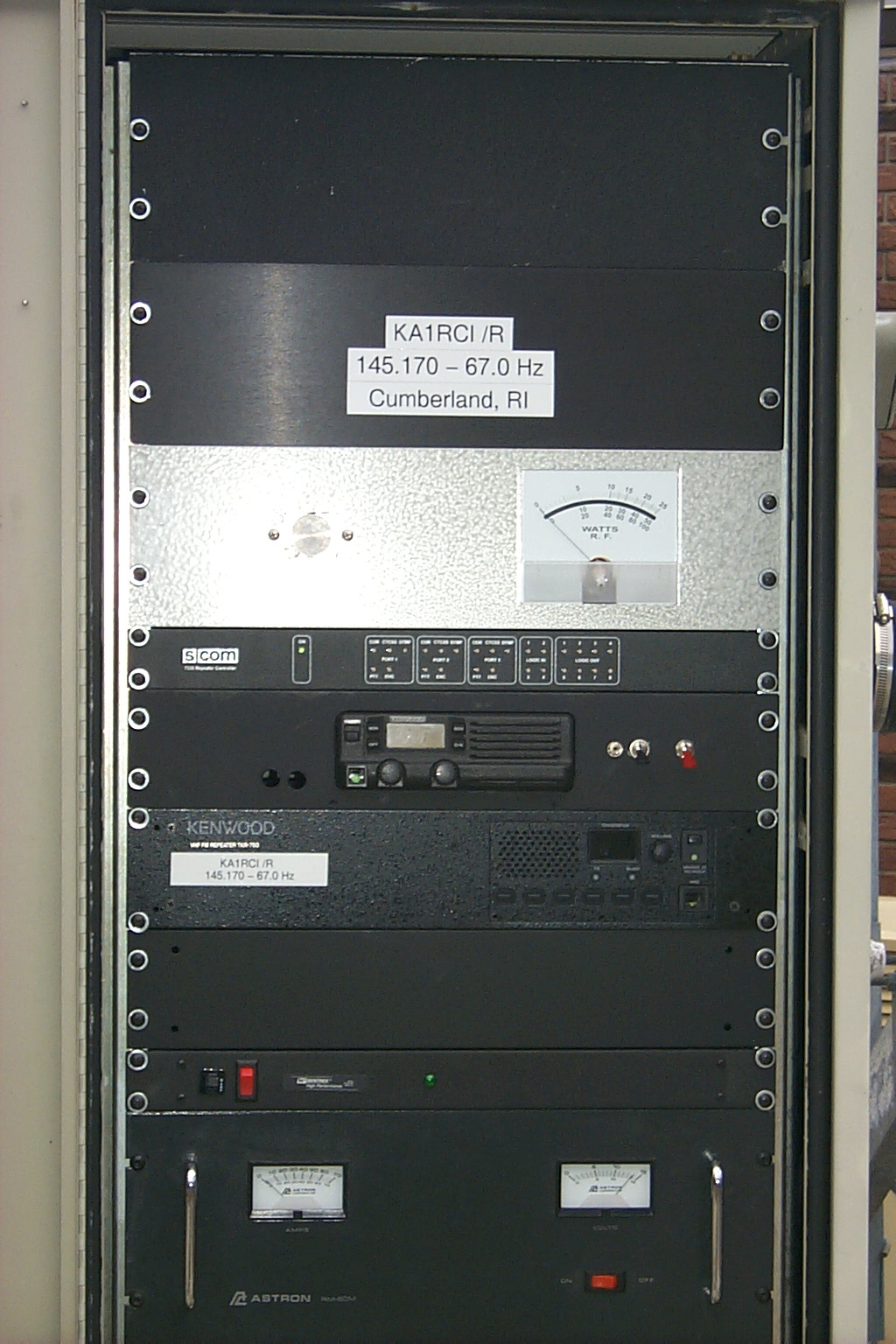
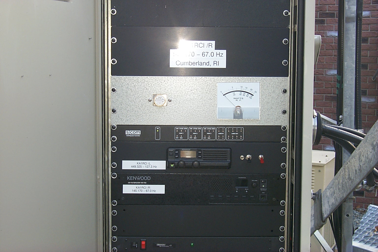
145.170 / 144.570 with PL 67.0 Cumberland - Rhode Island
Scroll to the bottom for latest updates starting 12.05.2015
Thirty years of History...
First Established as KA1BQP in 1987 Trustee / Sponsor KA1JNP /SK - R.I.P
After moving to Rhode Island in 1984 one of the first FM repeaters that I worked on was 145.170 which had been built by Matt KA1BQP. Matt had built the repeater using two older Motorola radios, donated by Joe (K1CR) WA1RBT, and Matt had the repeater on the air for testing in northern RI for a few months before selling it to Bill KA1JNP.
Bill moved the repeater to his home in Cranston and I found myself up on Bill's roof on December 26th 1987 installing a new antenna for the repeater. These video clips taken by Dick K1CVP show the gang assembled as Bill and I secured the mounts to the side of the house and climbed up onto the roof to install the hard-line.
Bill KA1JNP - Steve KA1RCI - Joe WA1RBT (K1CR) - Mike KO1X Syl N1DKF - Dick K1CVP - Georgia KA1NKF - Tim KA1QYK
Insert Video Clip Here
This video clip show the gang reassembled in the basement with the repeater as Joe WA1RBT (K1CR) installs the connector on the hard-line.
Insert Video Clip Here
In this last clip we see Tim making the first contact on the 145.170 repeater as Joe flipped the Switch.
Insert Video Clip Here
Now twenty years later the same 145.170 repeater is back in northern RI being rebuilt as a new northern node on the KA1RCI repeater network. Bill and I worked together to re-coordinate the repeater at my site in Lincoln RI and I started rebuilding...
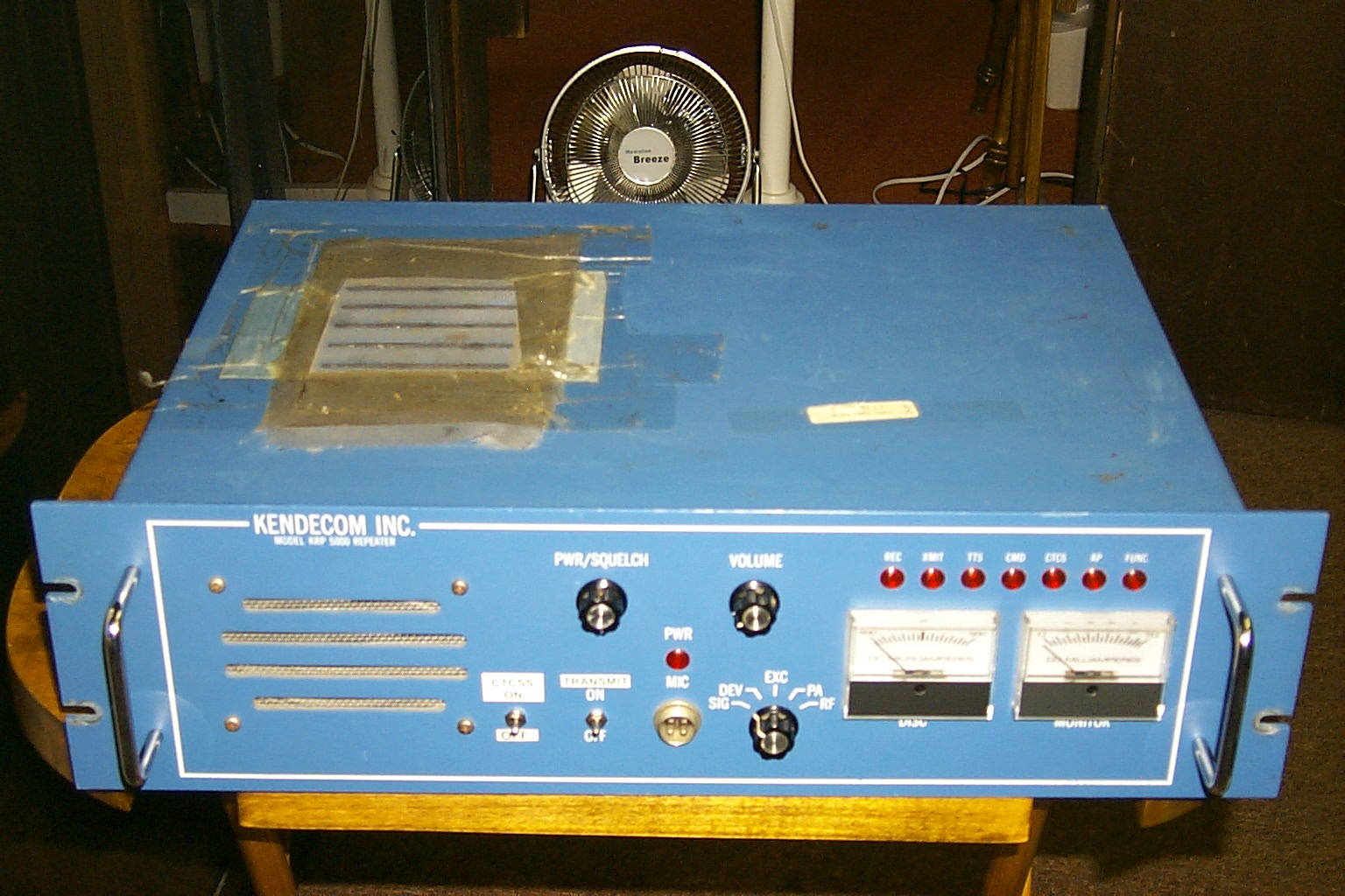
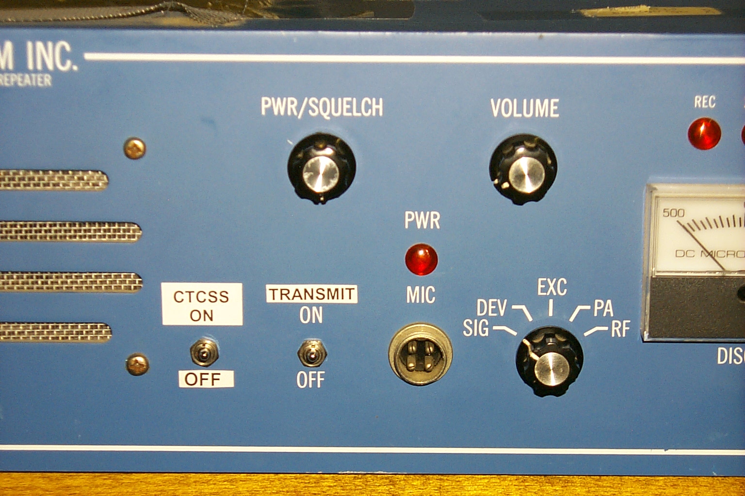
Repeater Rebuild Fall 2007 - Steve KA1RCI
The initial project planning / repeater configuration
Bill KA1JNP asked me to repair / upgrade the 145.170 repeater and find a good site in northern Rhode Island where we could move the new system. I picked up the hardware from Bill and brought it back home to Lincoln to get the repeater back on the air and start the planning phase of the rebuild.
While sitting down with Bill over a "Cup" we discussed plans for the rebuild
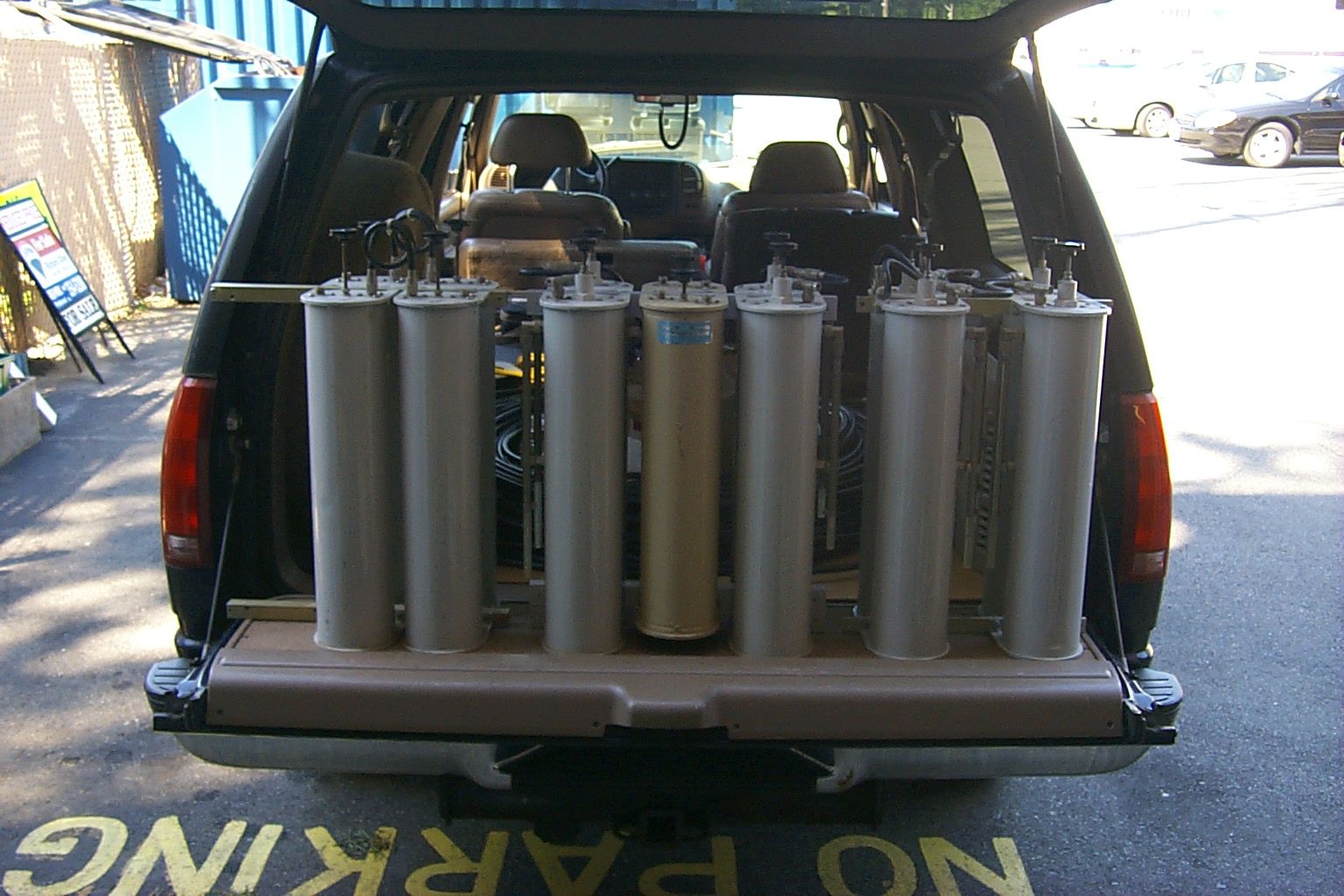
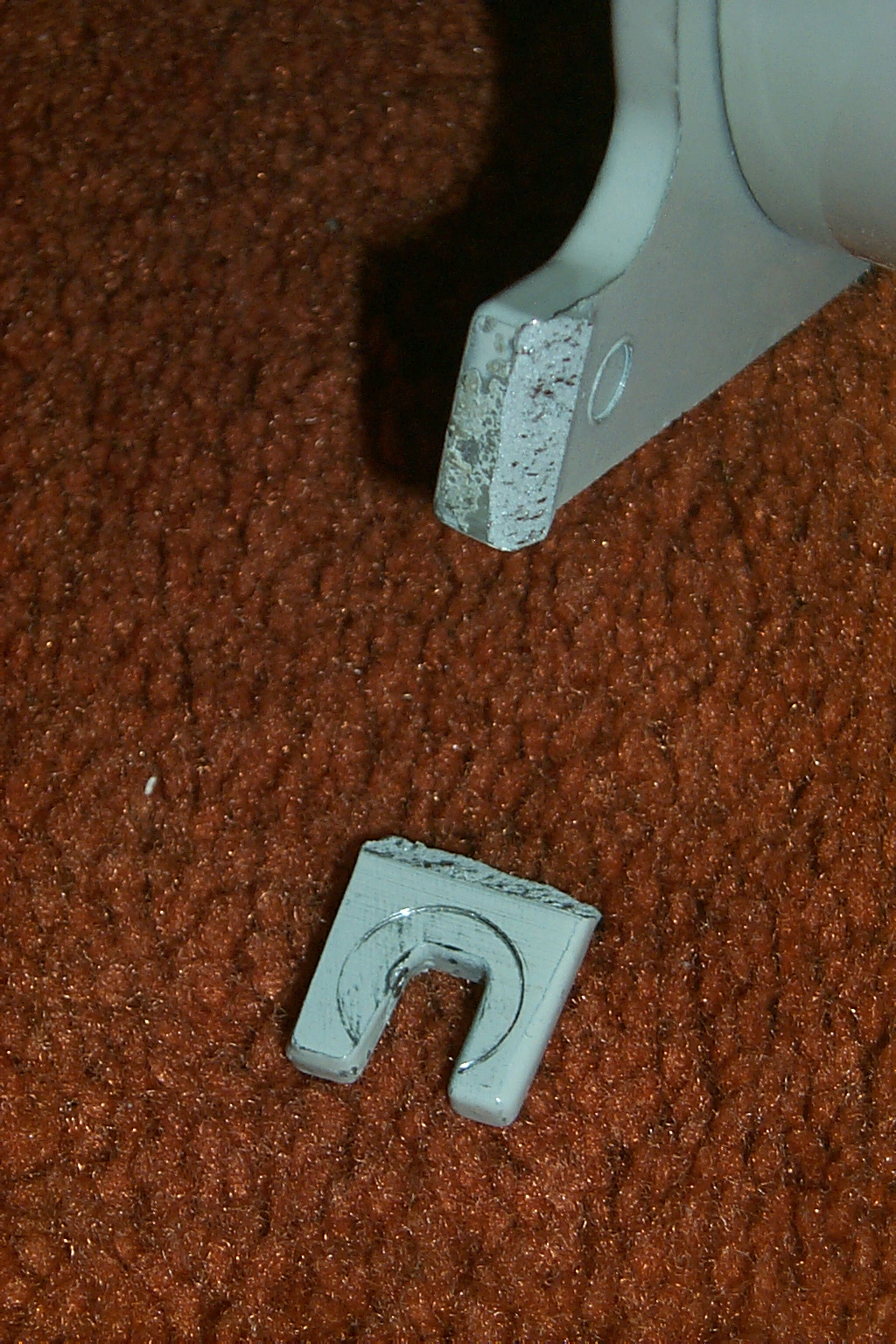
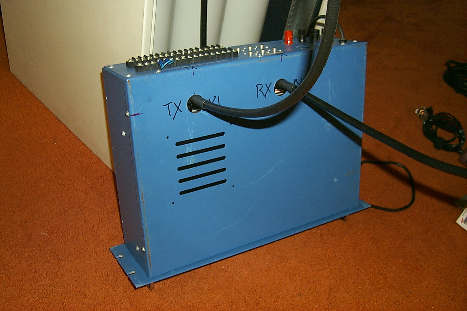
Bill helped me load everything into the Big Blue Beast and I brought the repeater back to my QTH in Lincoln to disassemble all the hardware and evaluate what could be reused and what needed to be replaced.
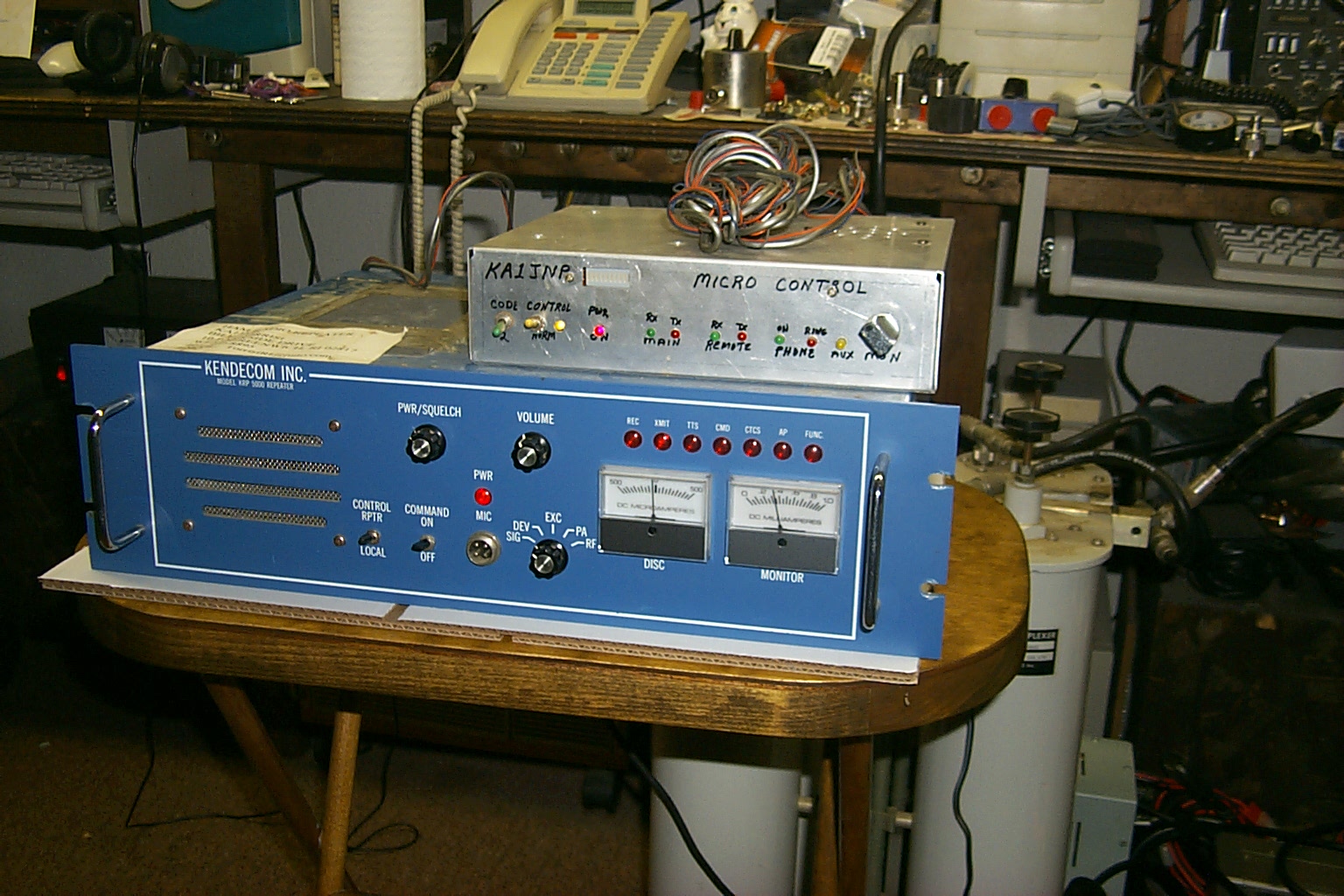
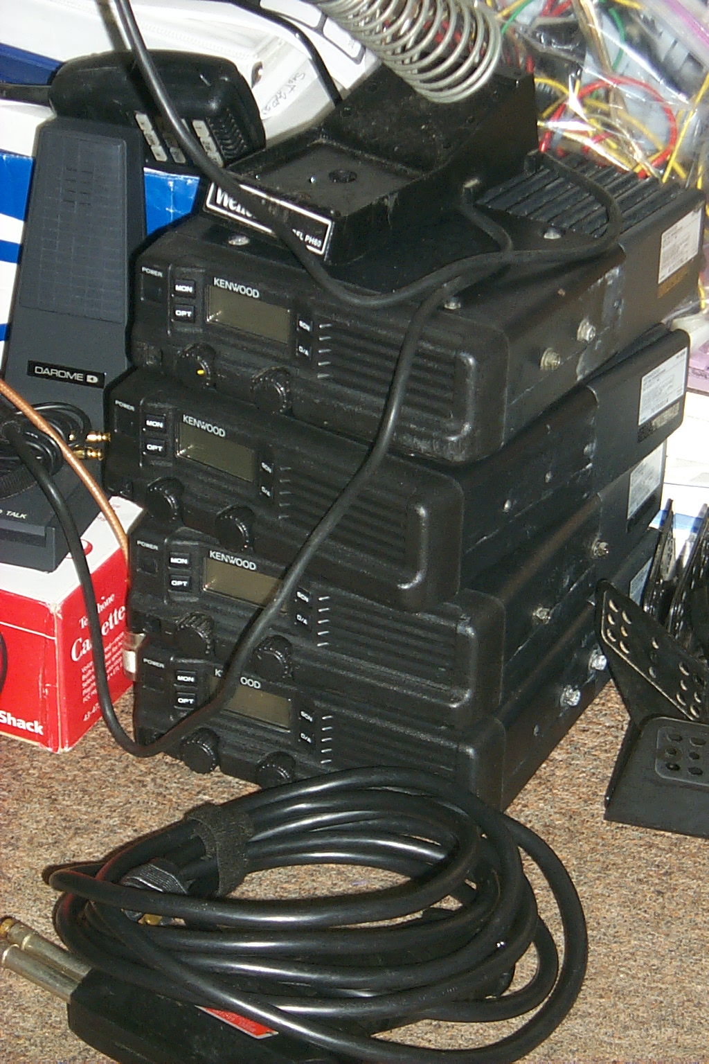
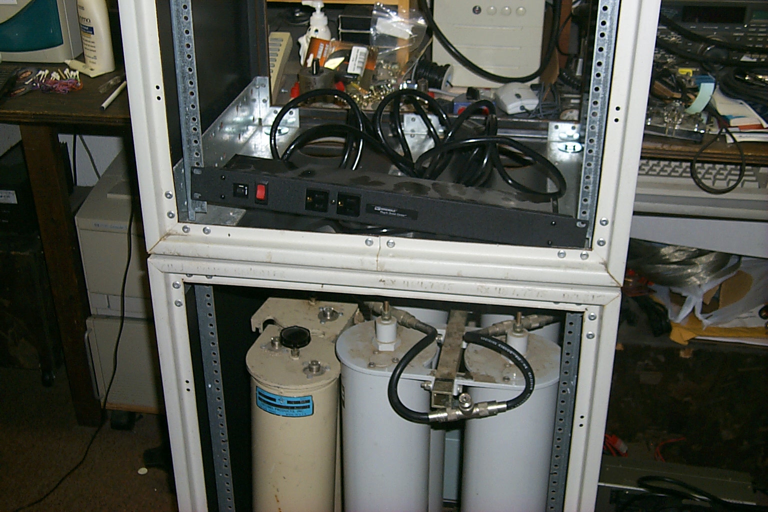
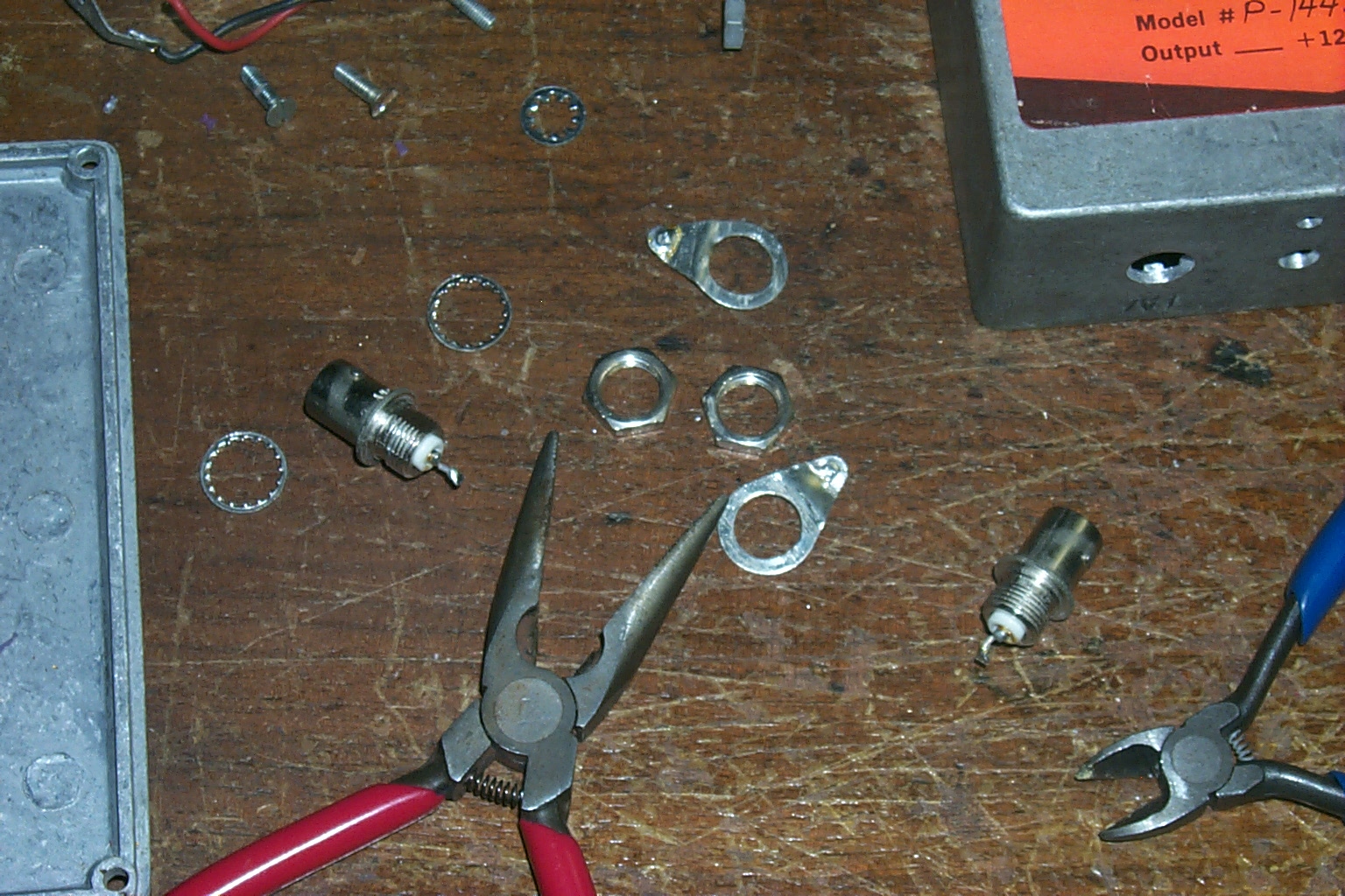
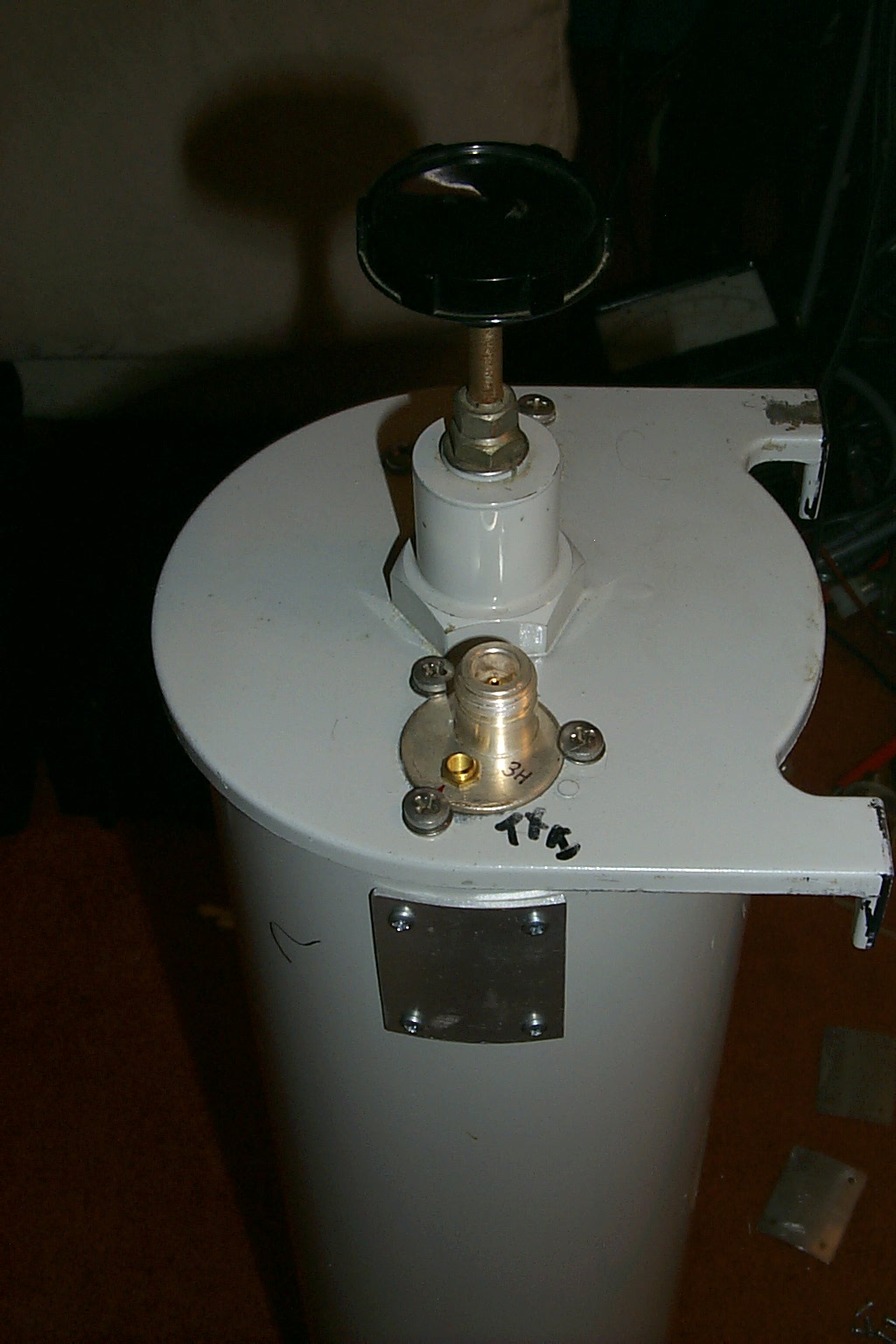
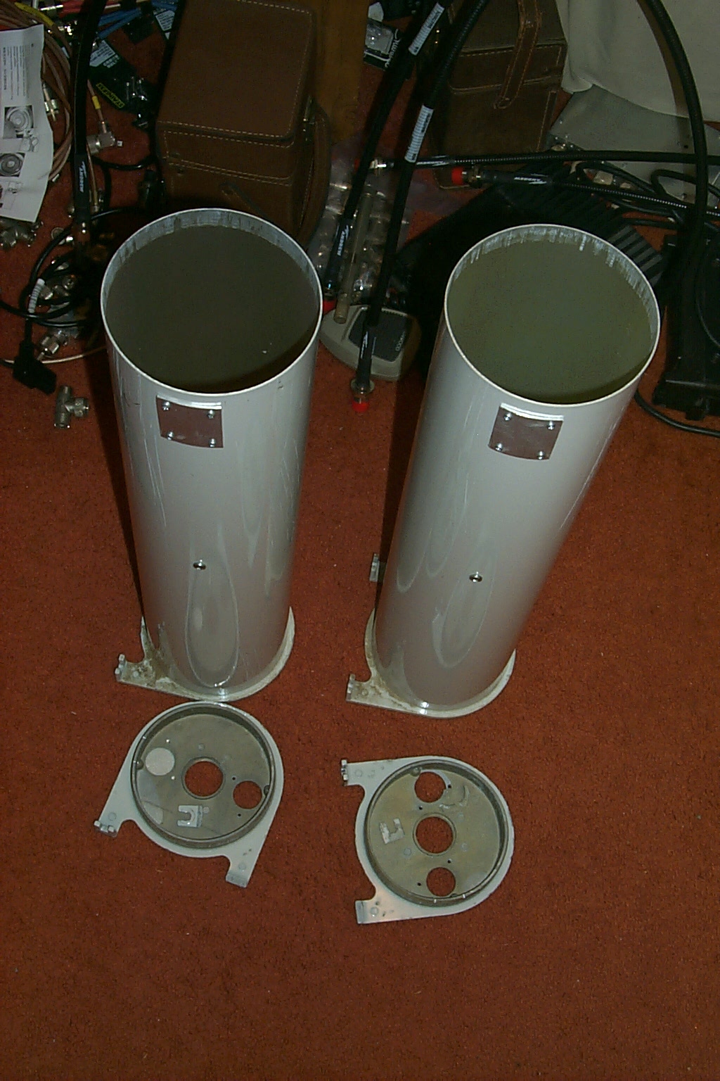
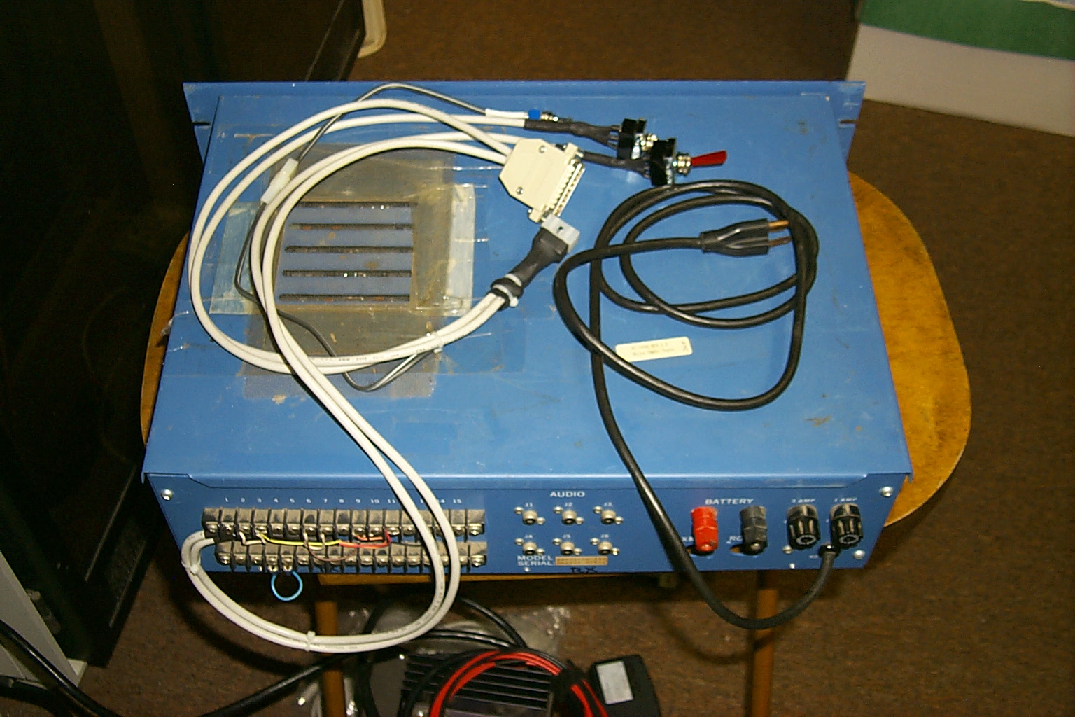
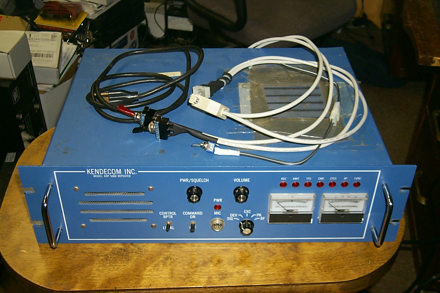
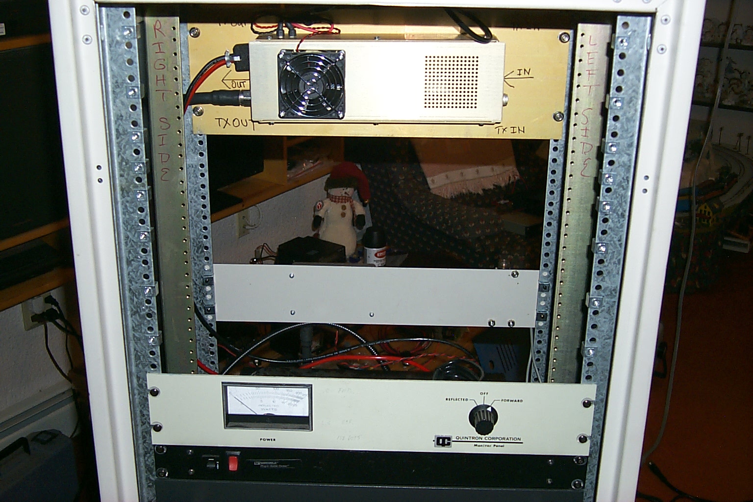
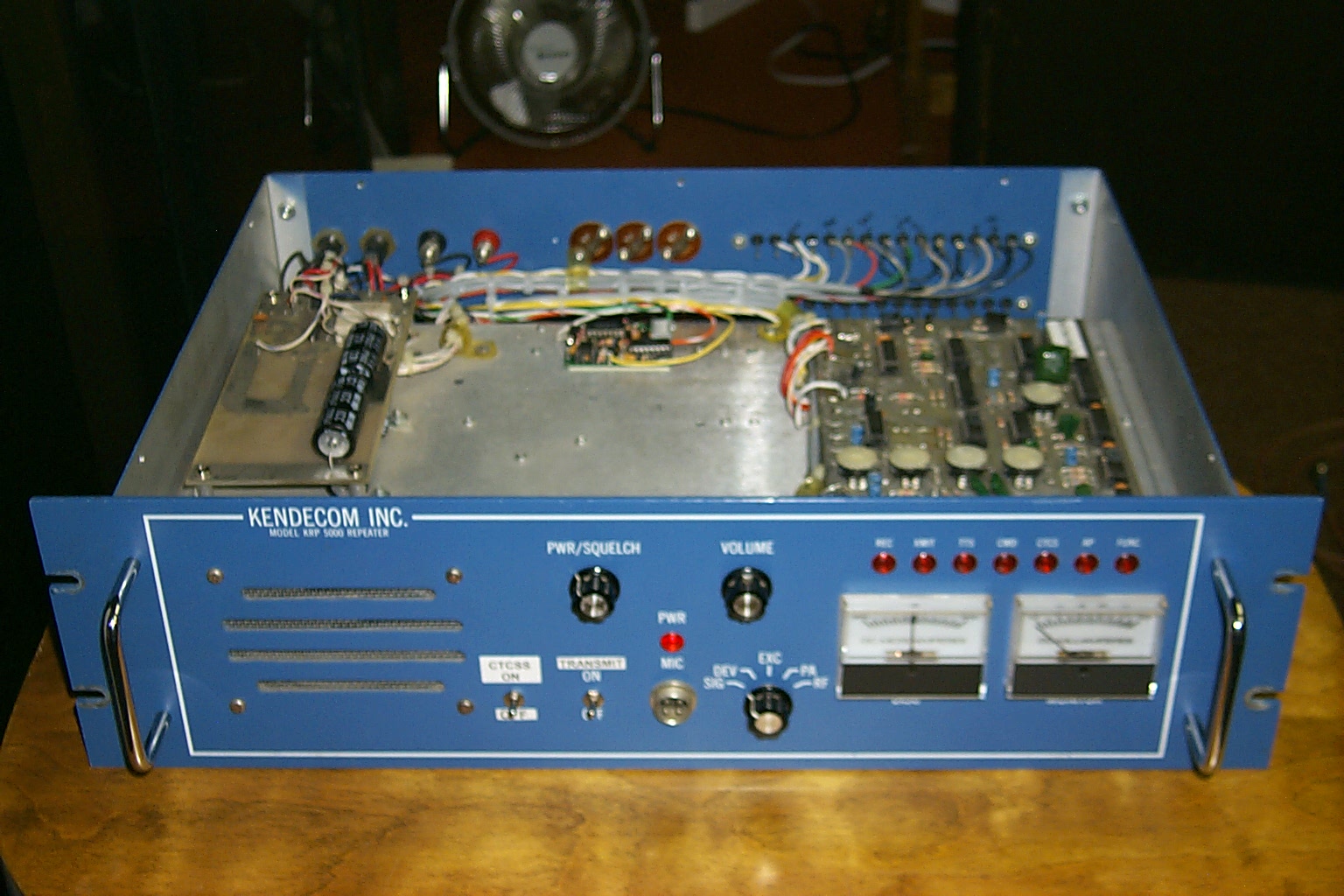
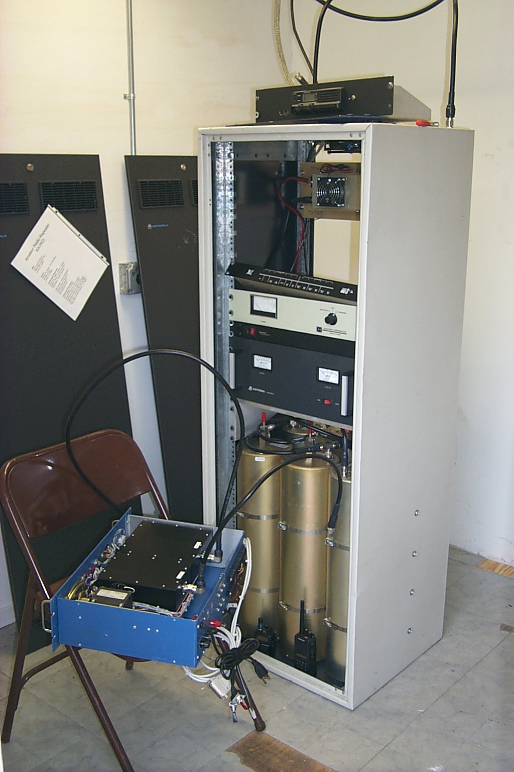
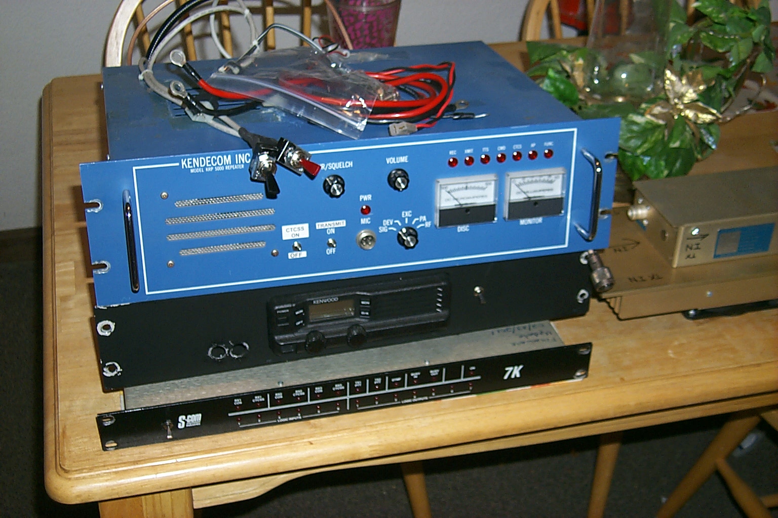
Something to build on ...
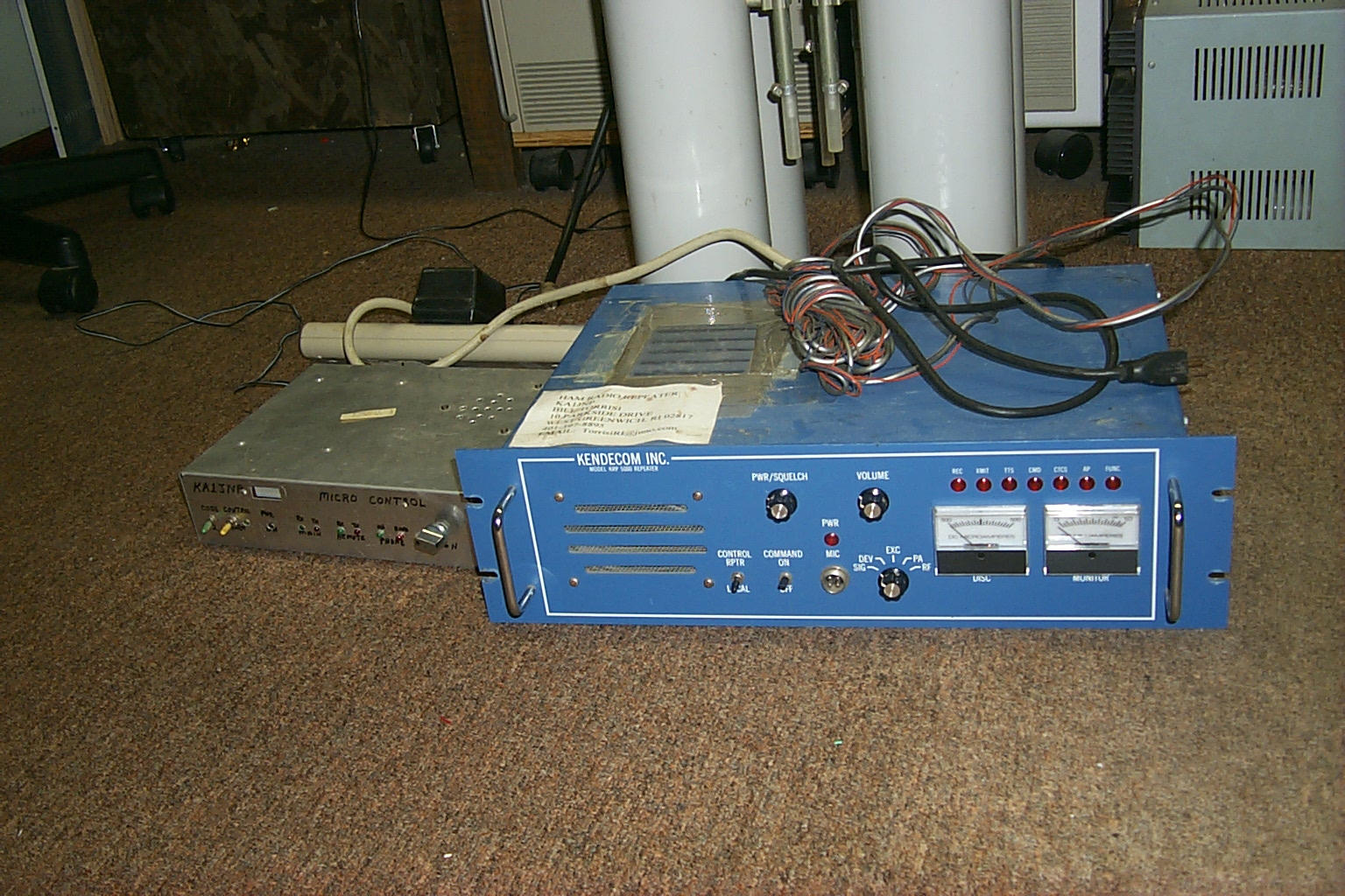
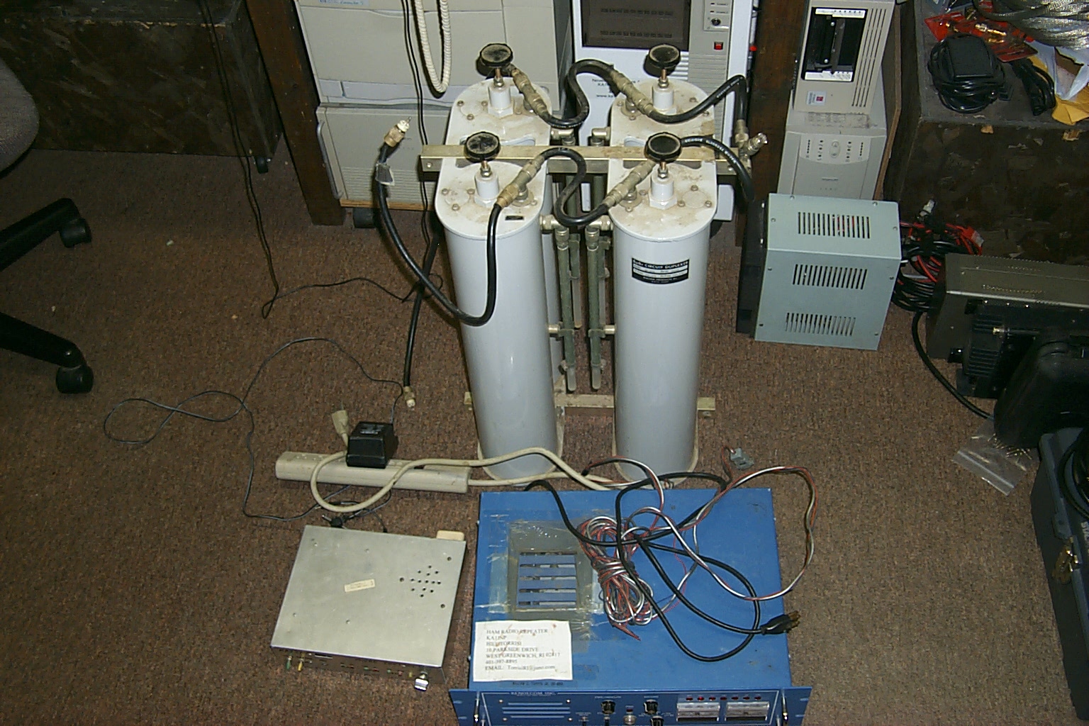
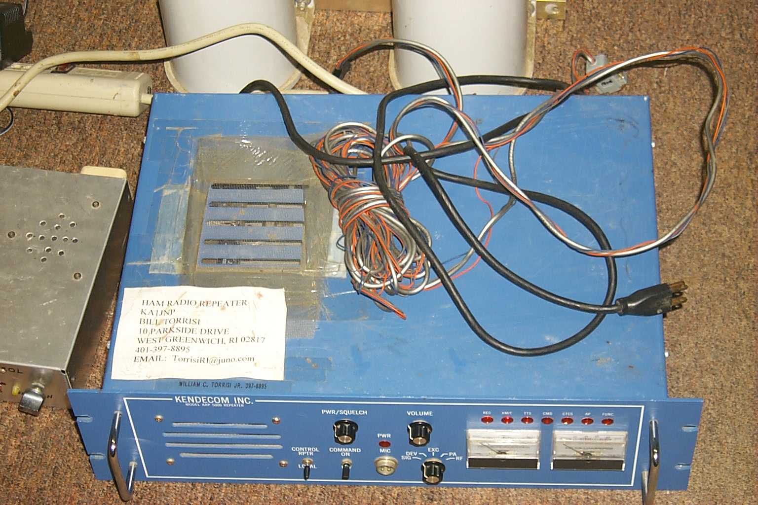
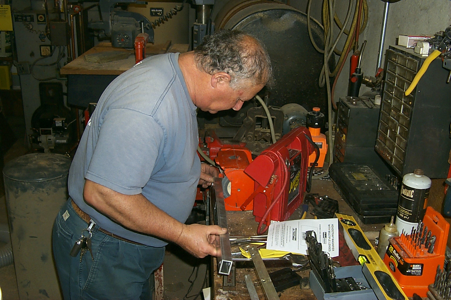
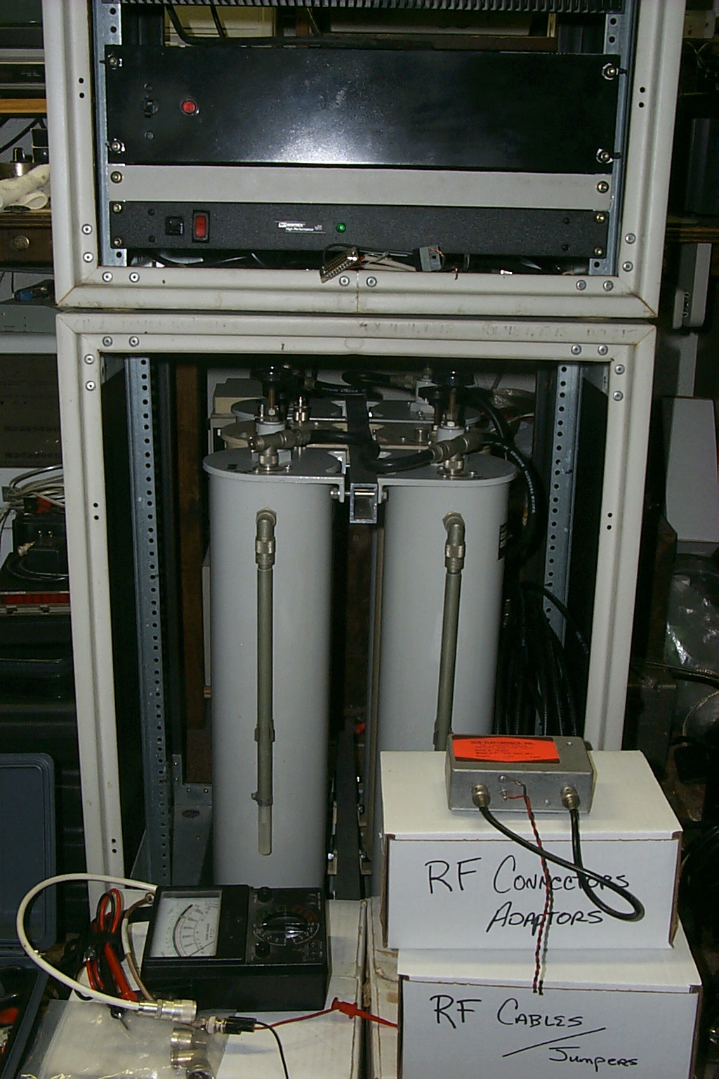
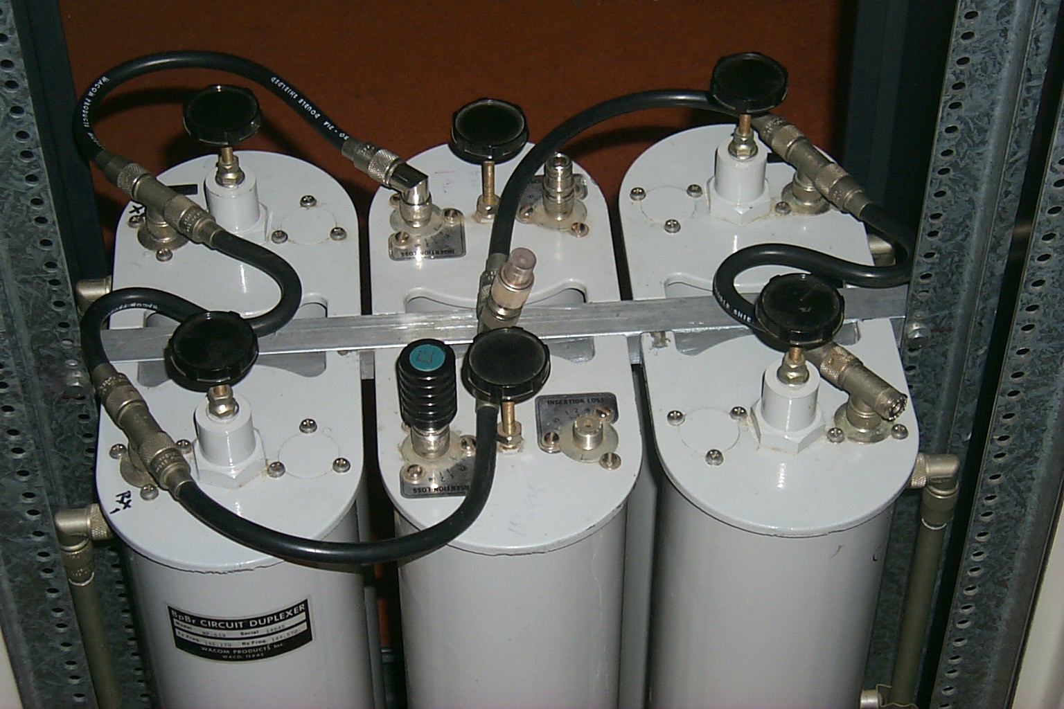
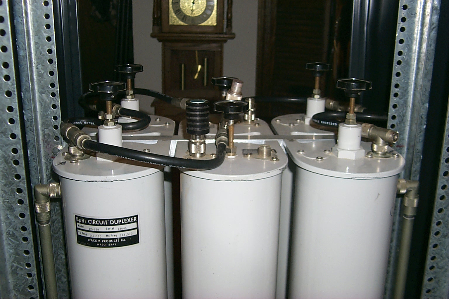
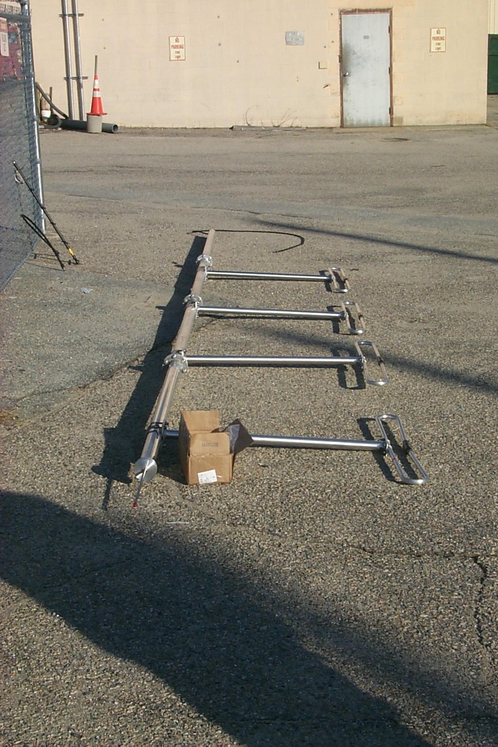
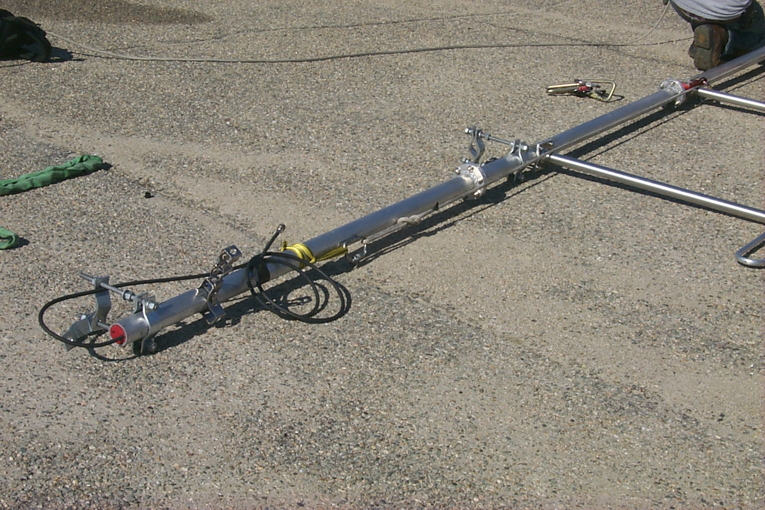
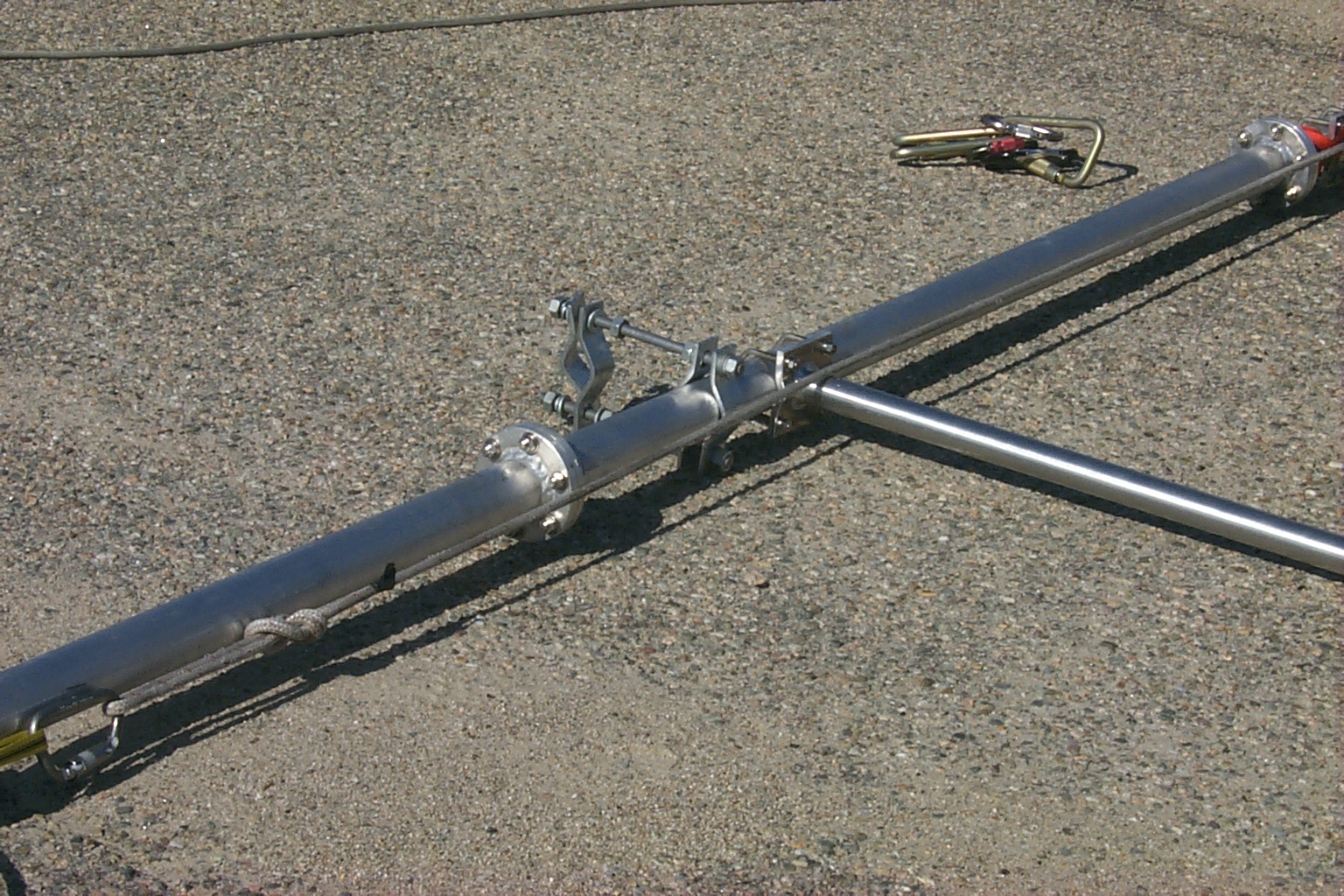
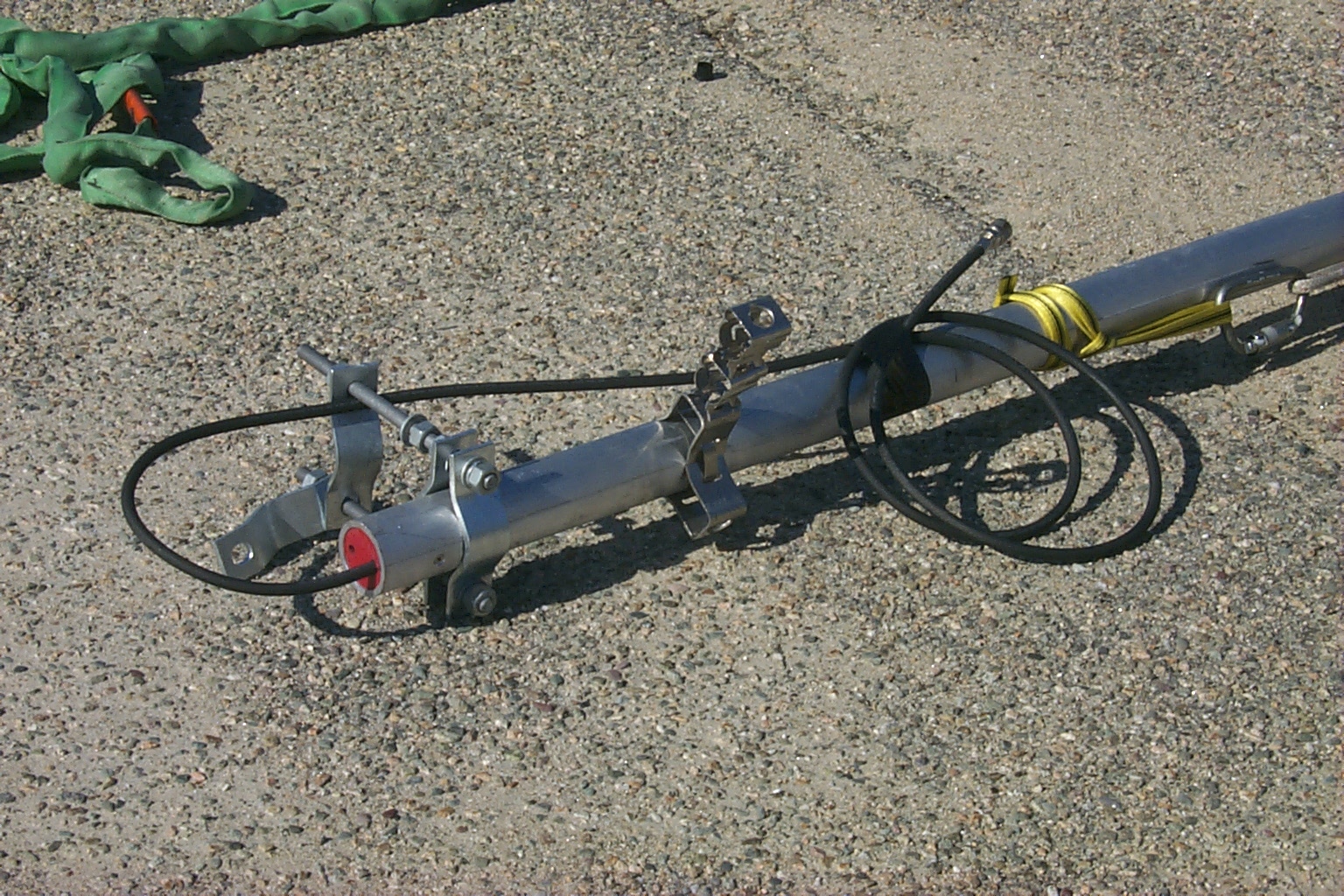
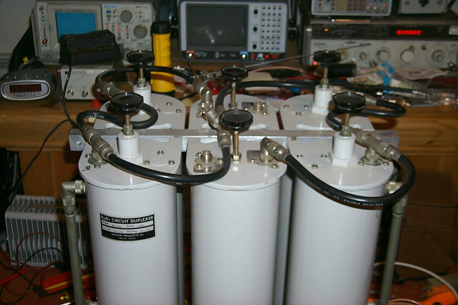
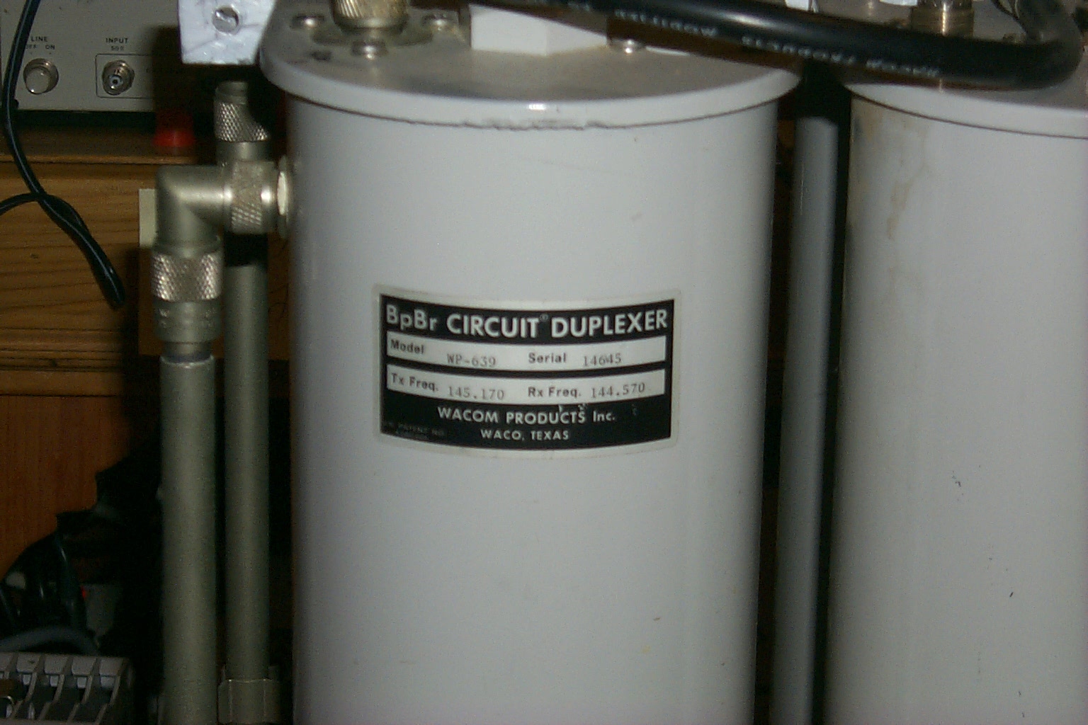
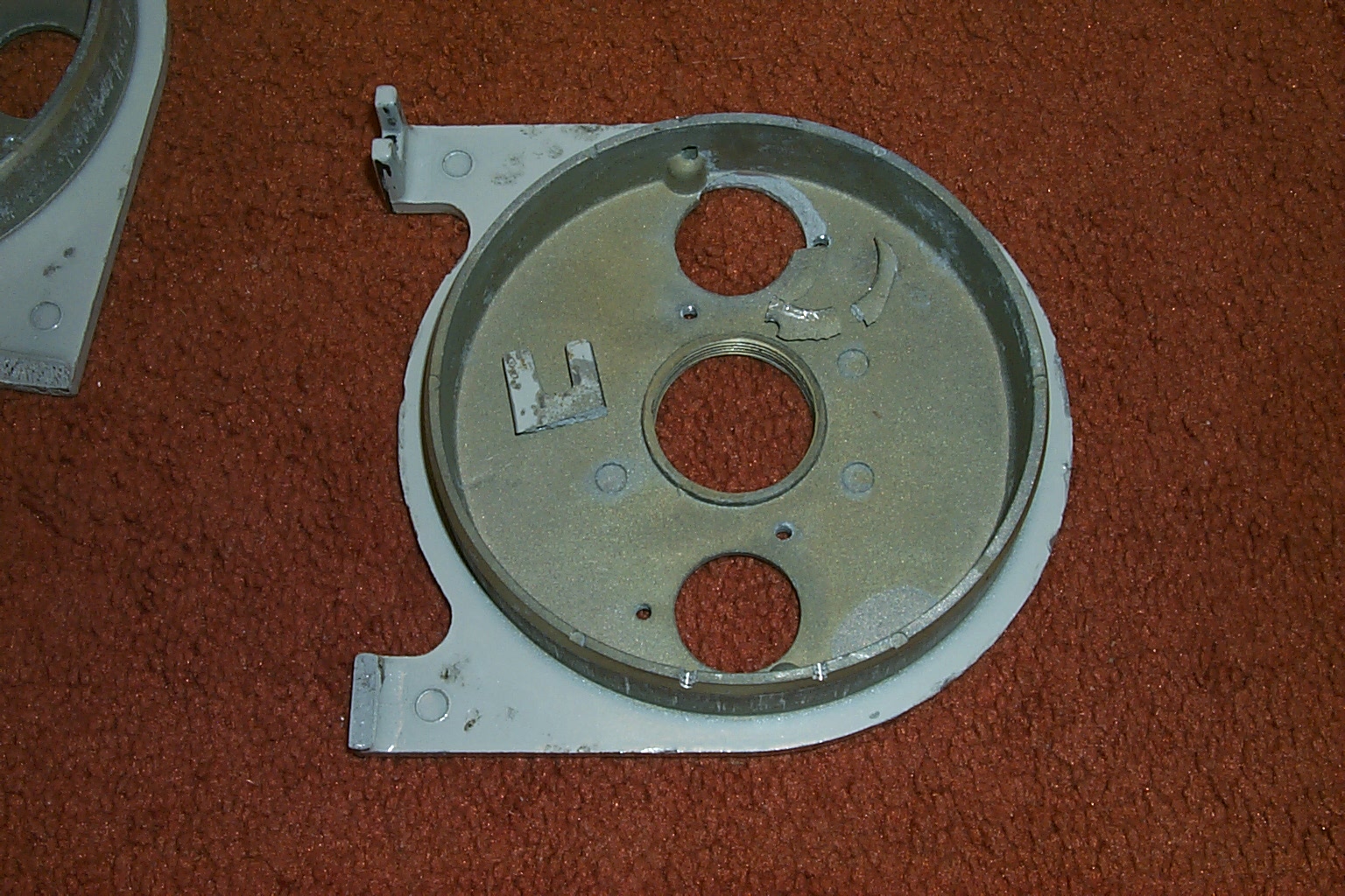
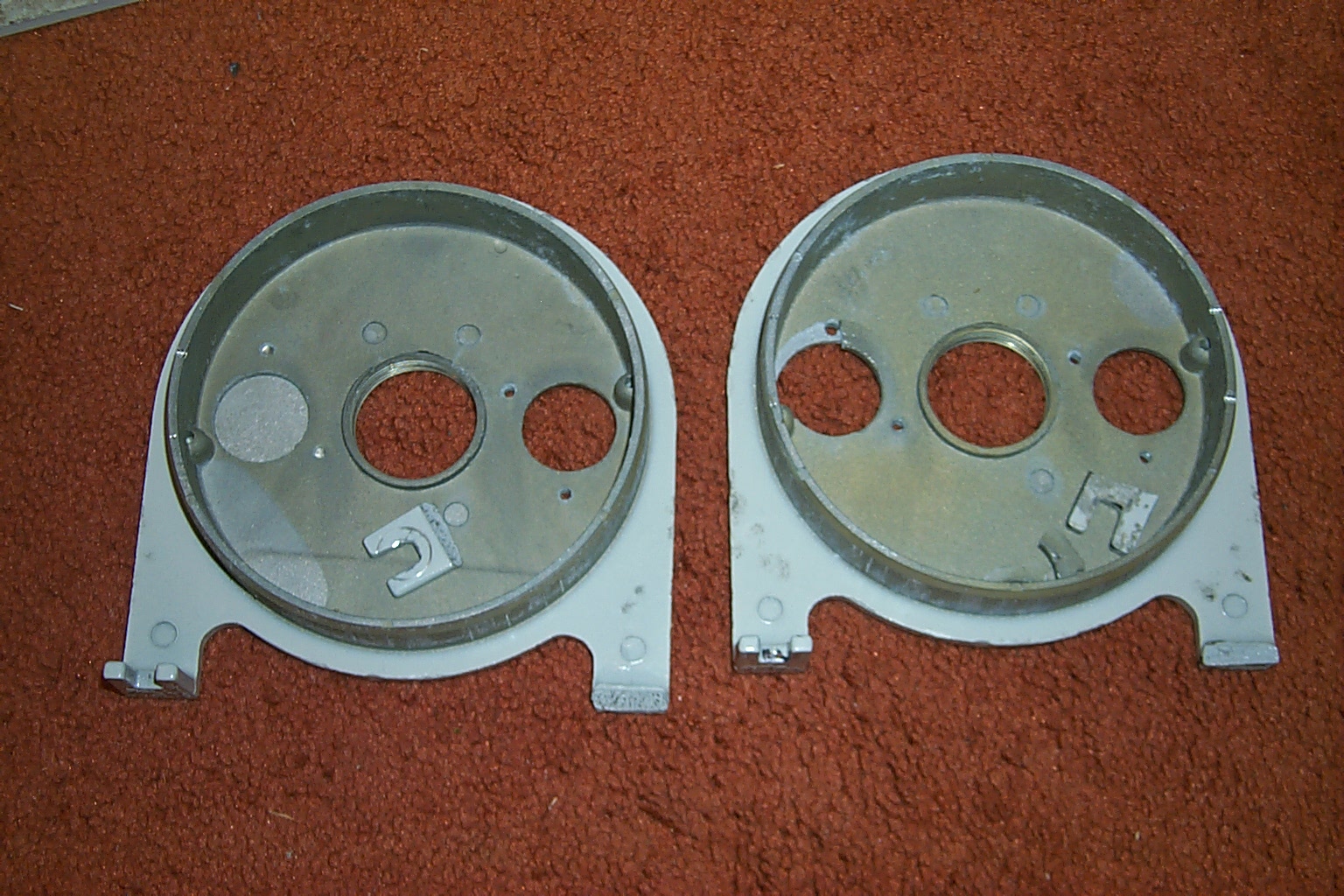
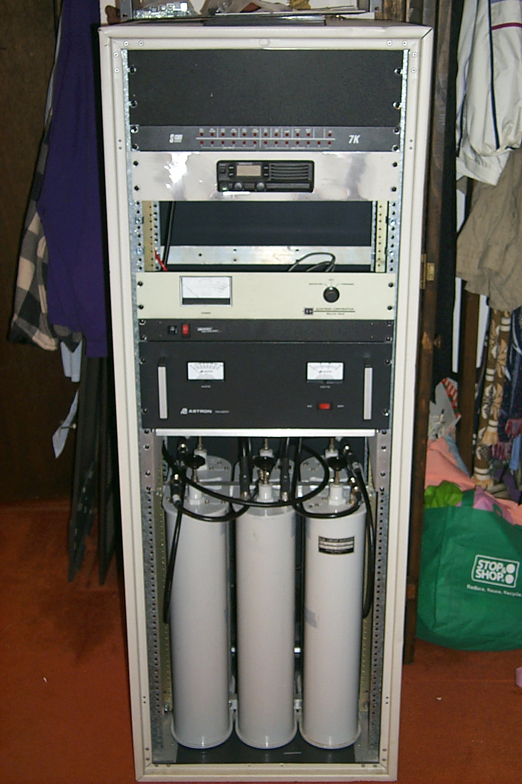
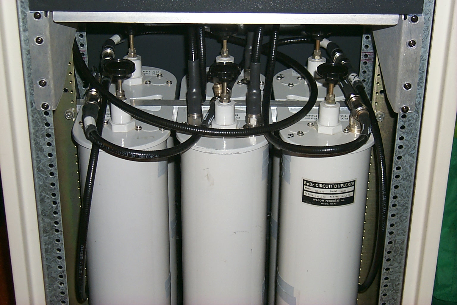
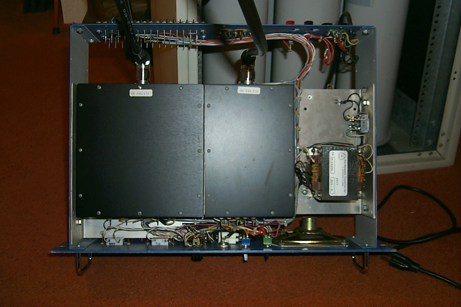
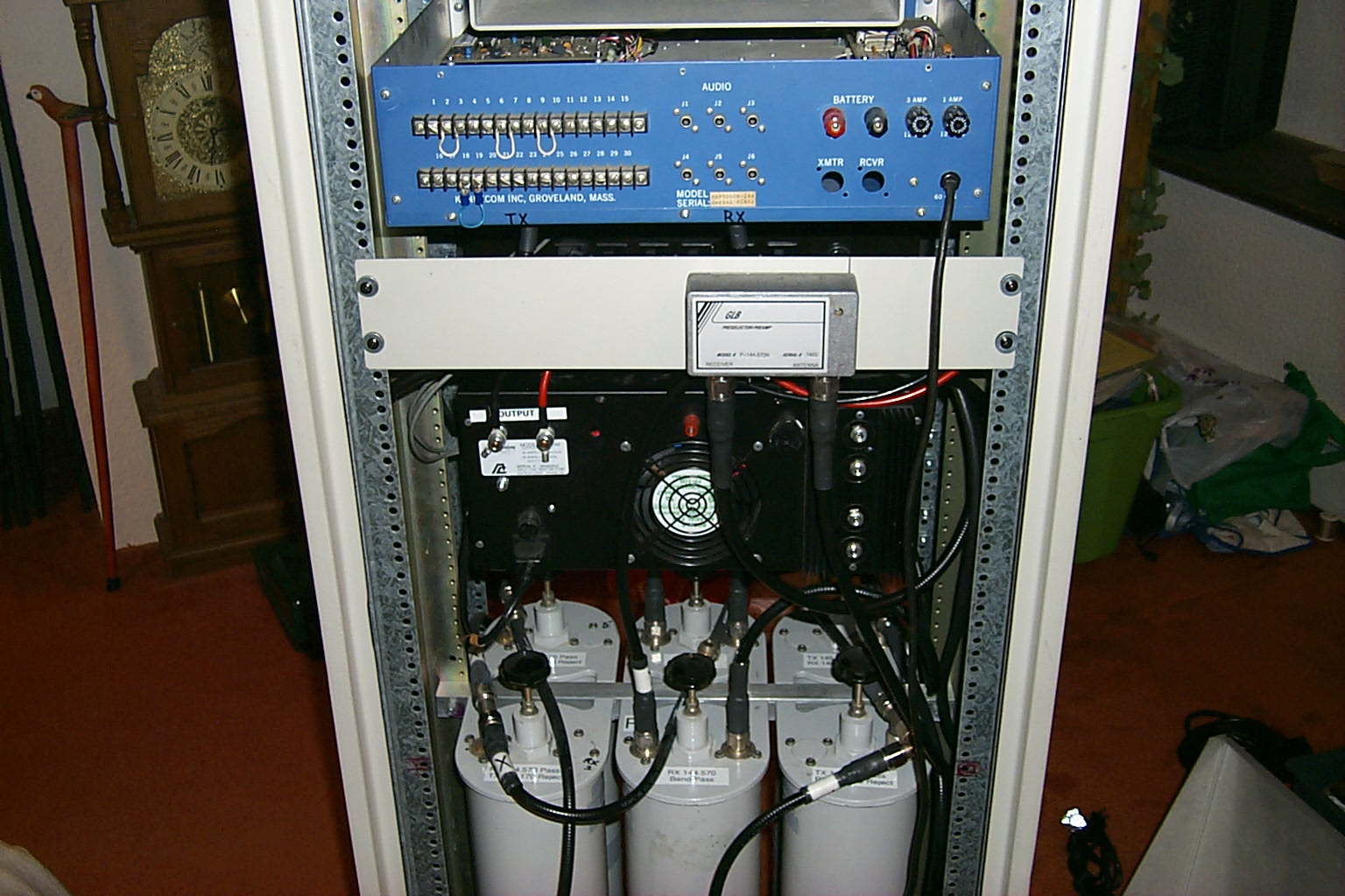
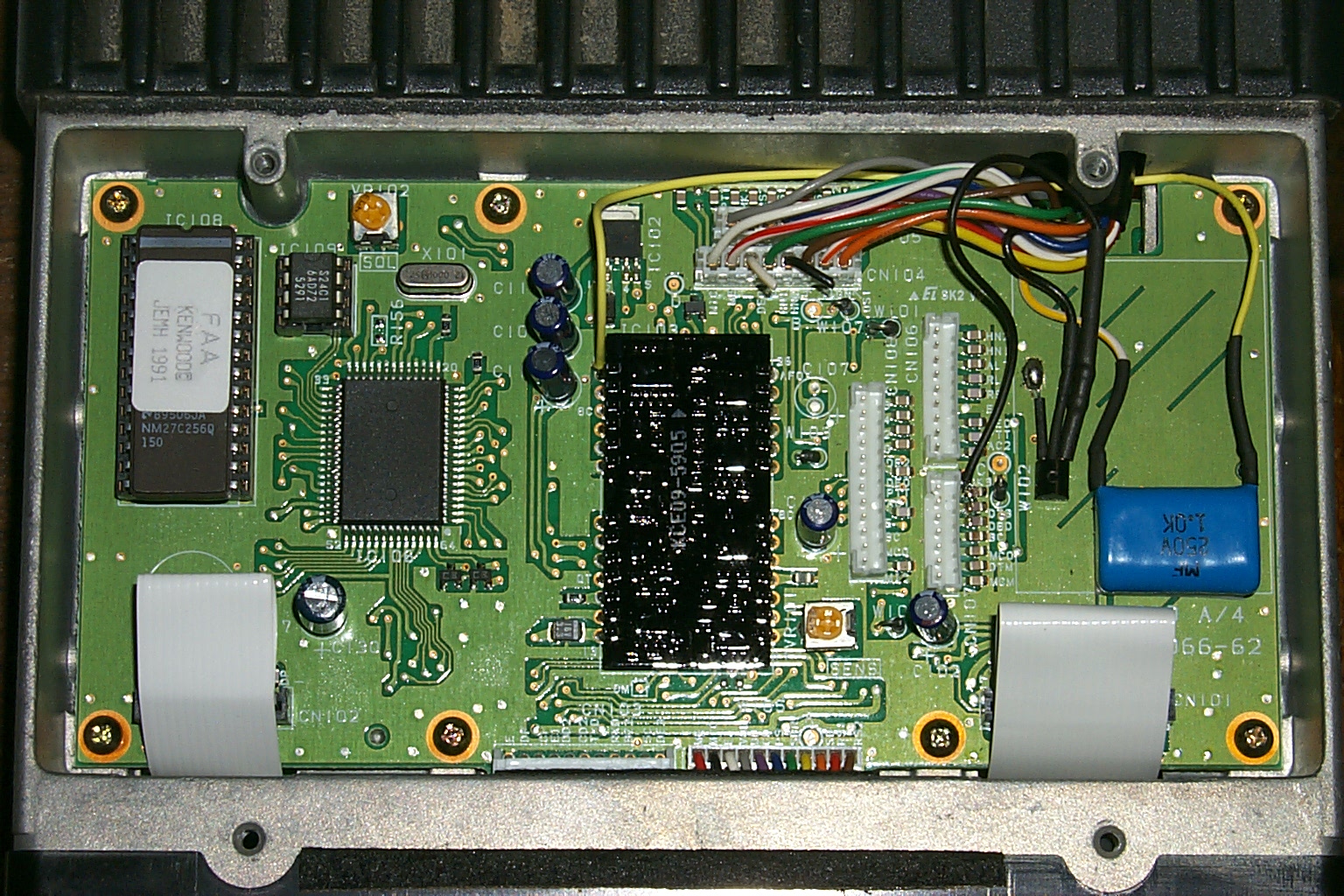
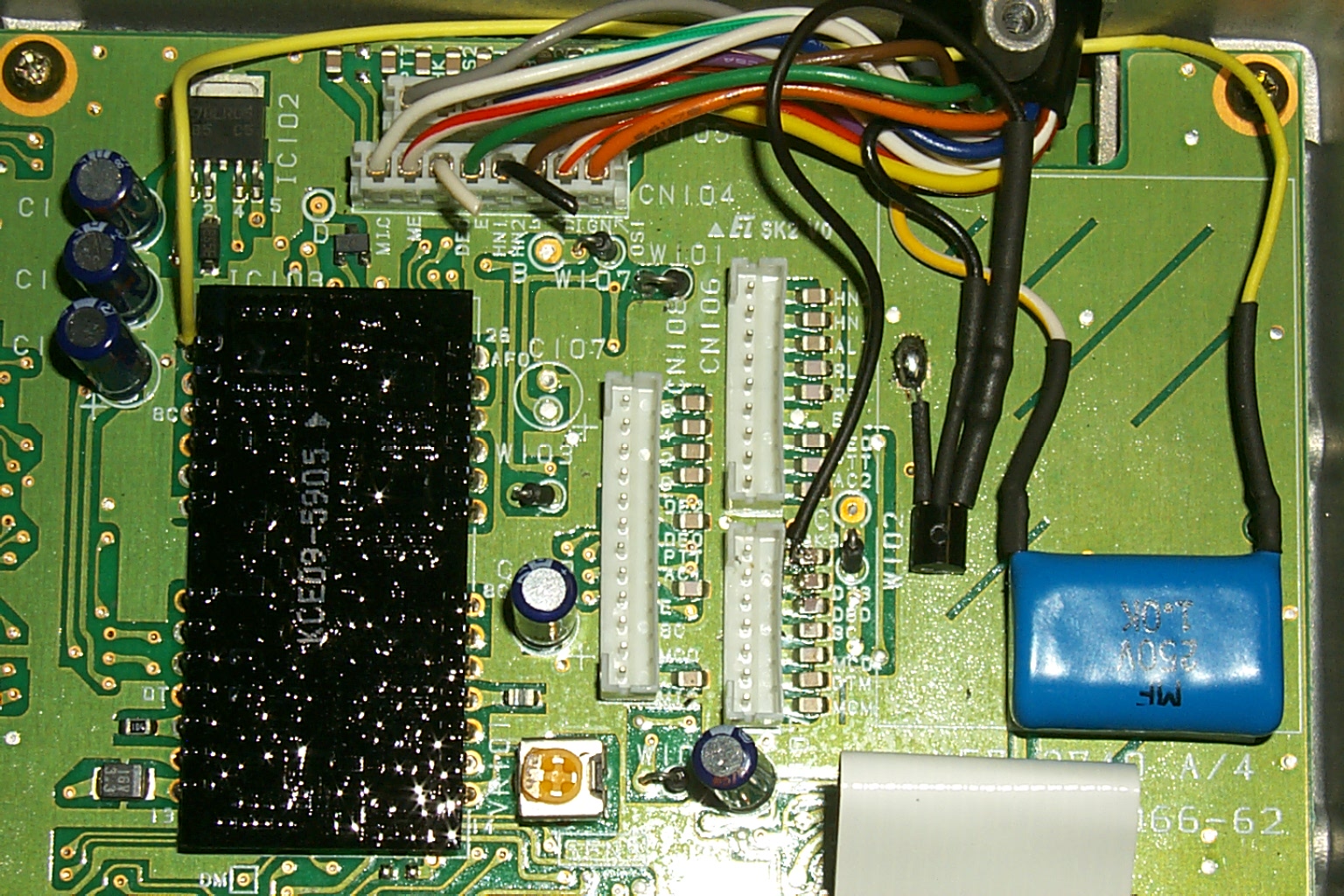
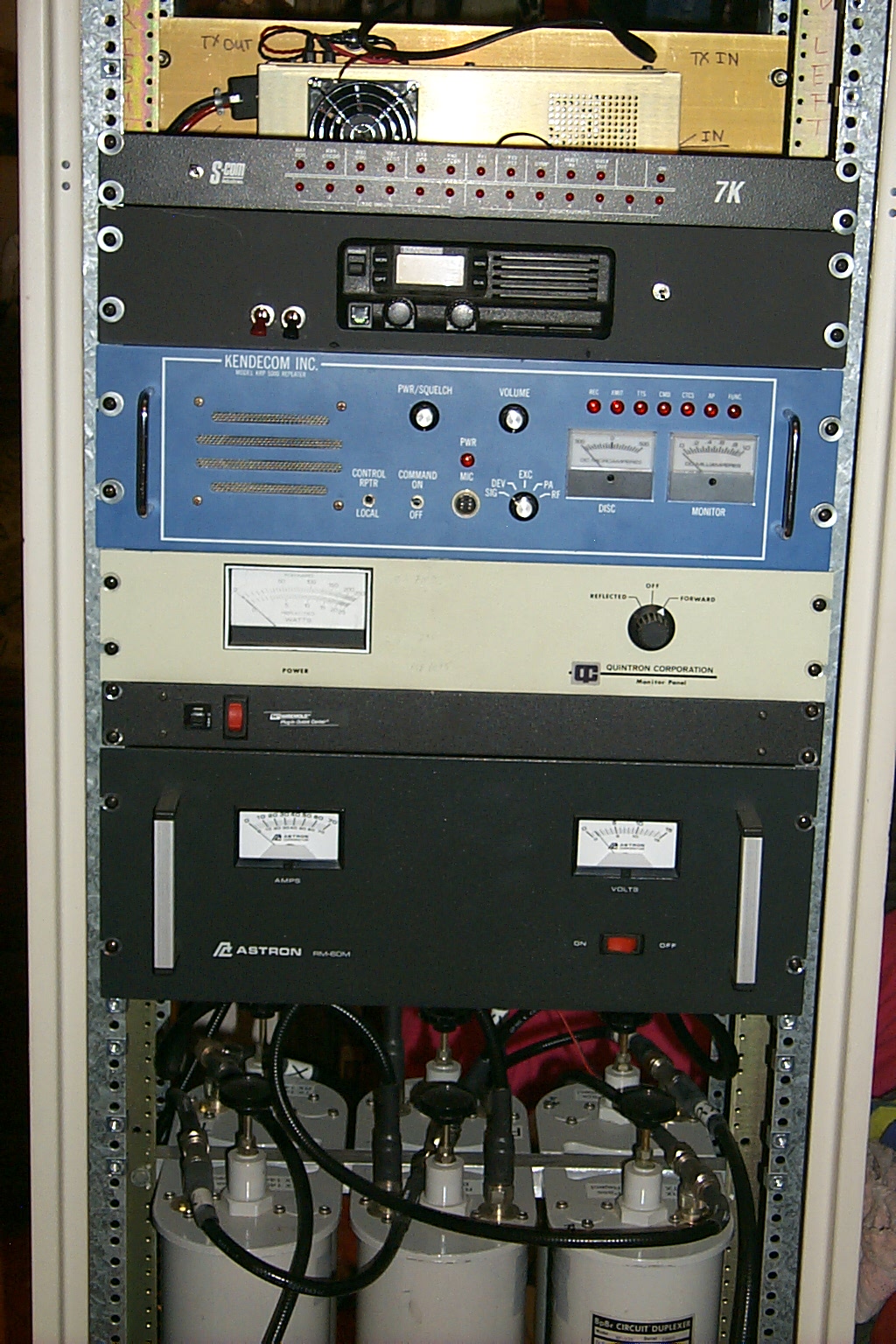
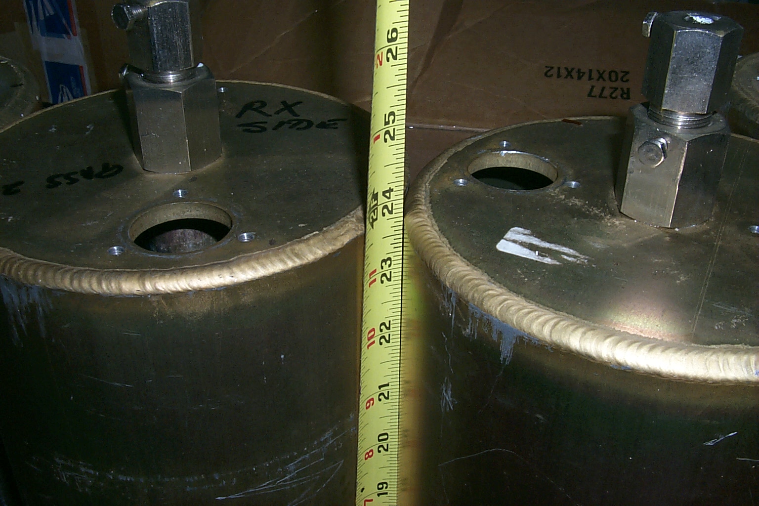
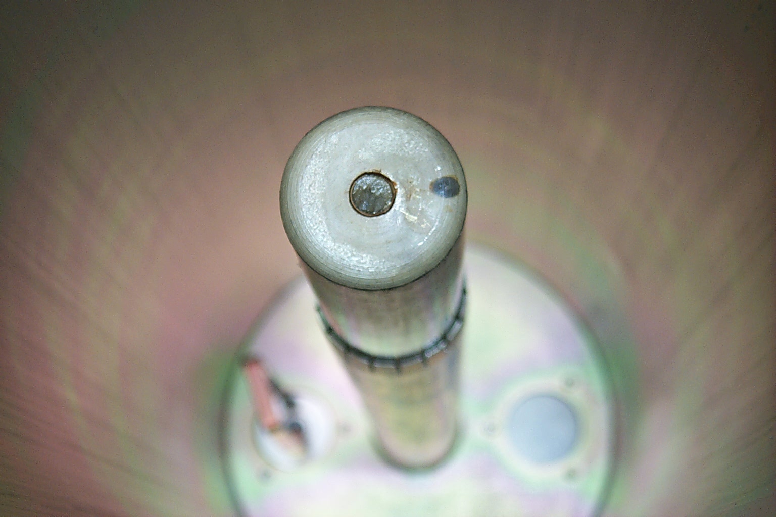
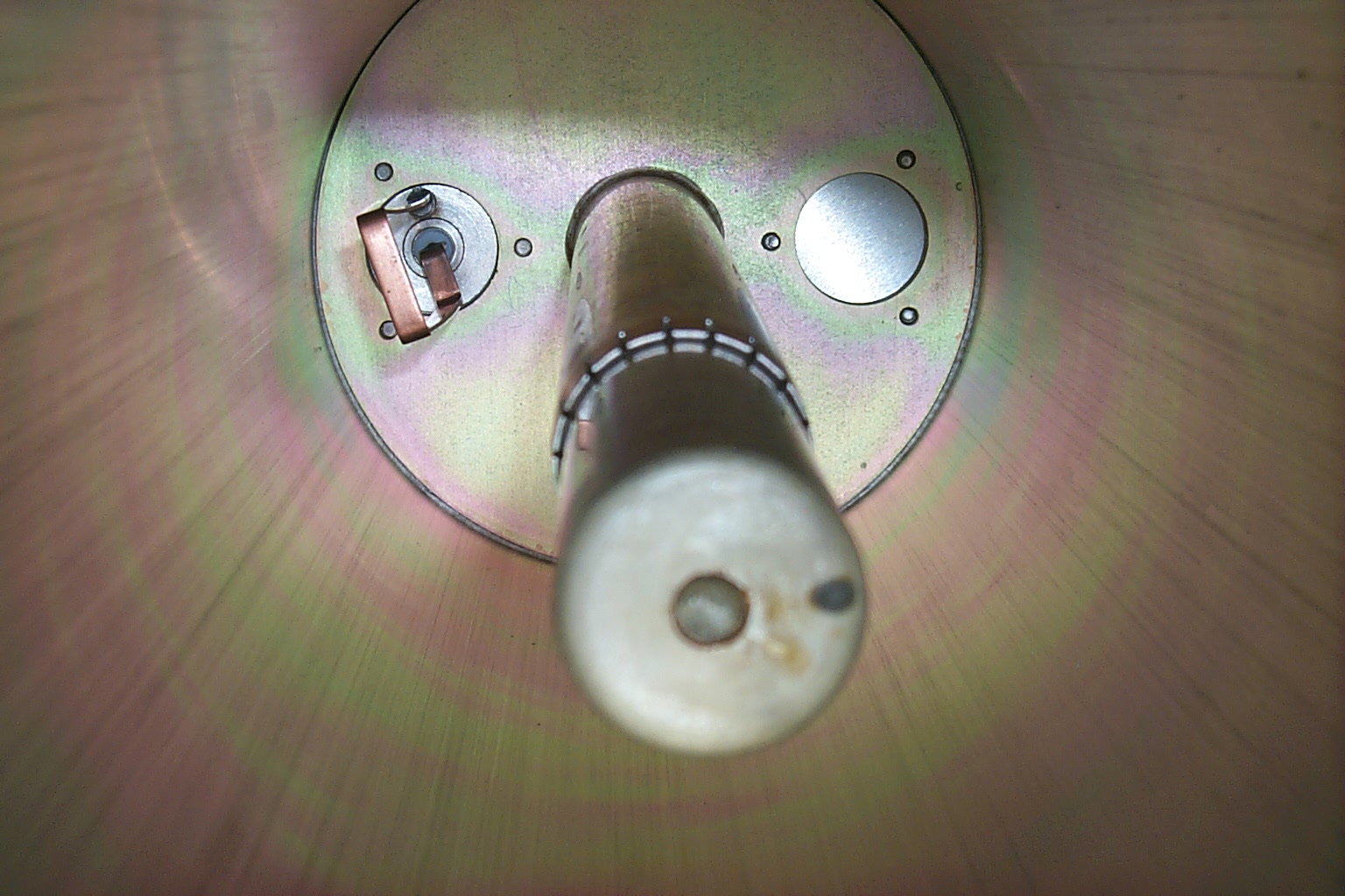
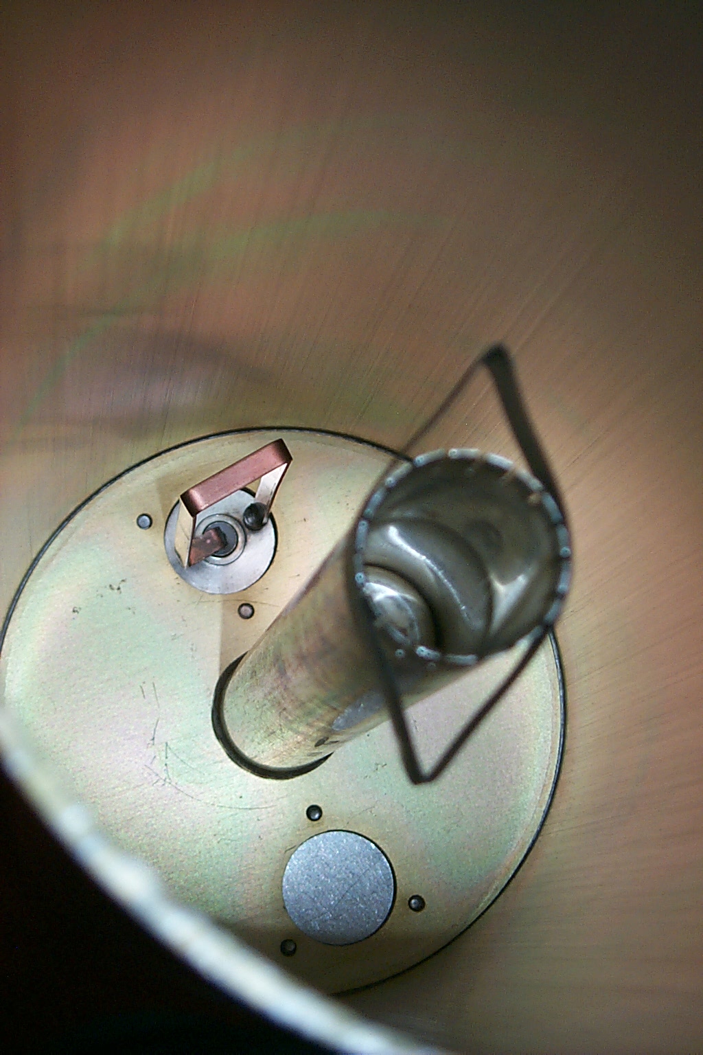
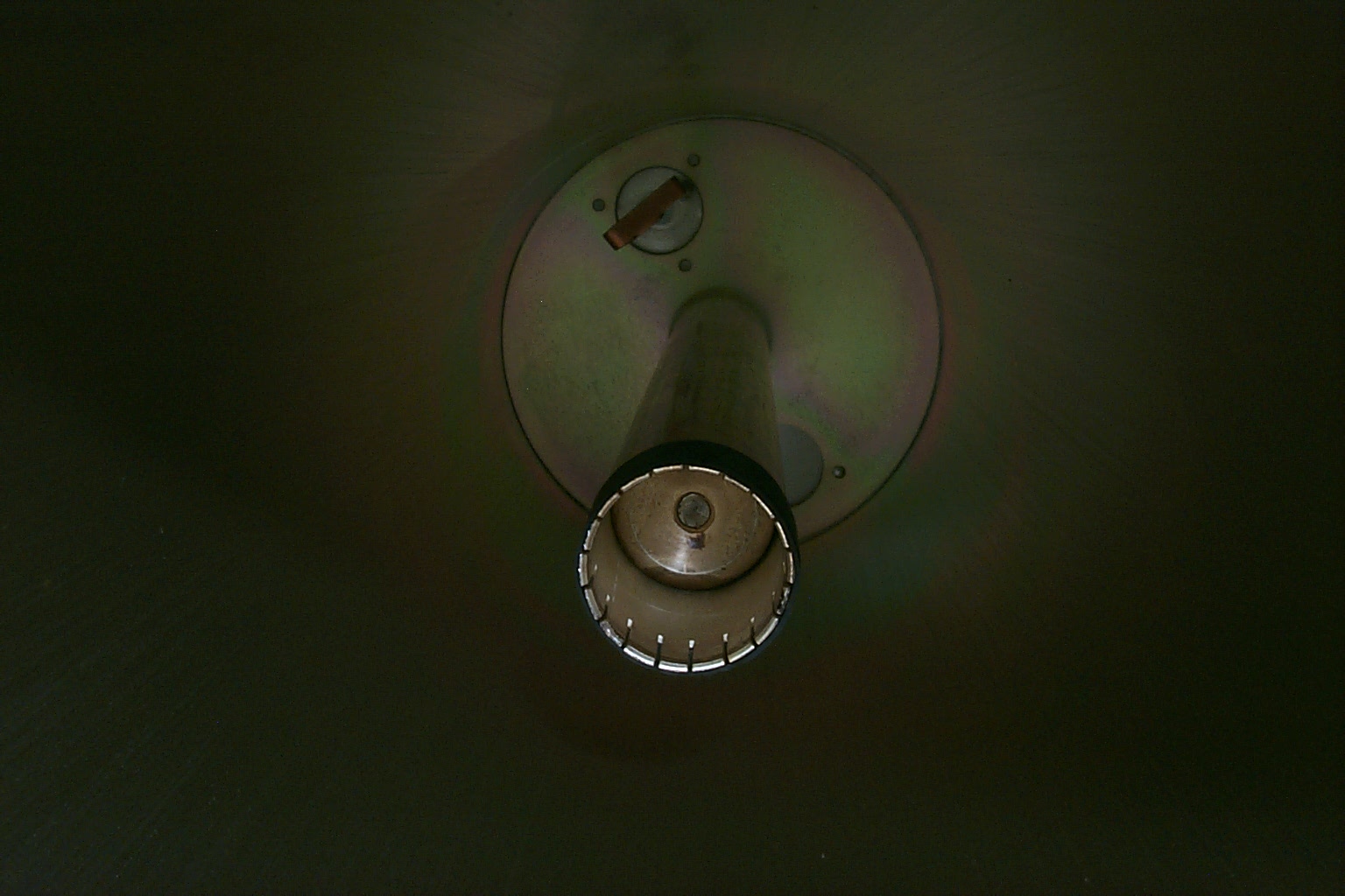
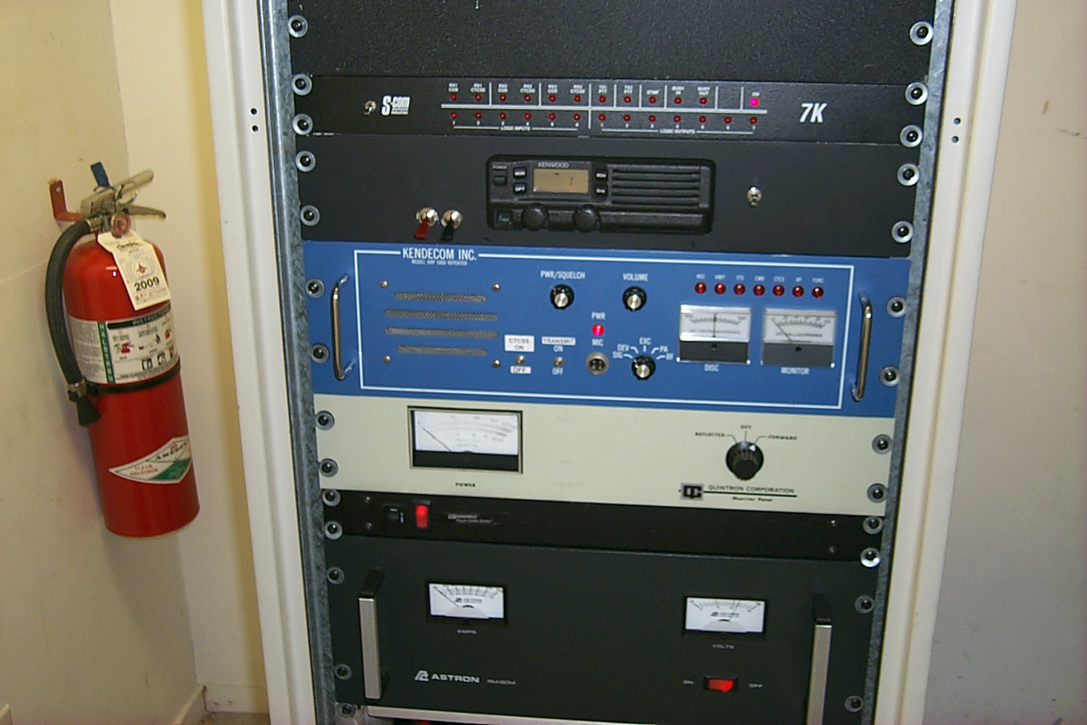
These photos were taken just after bringing the repeater into the house showing the Kendecom repeater, add-on external controller, and the duplexer that I picked up from Bill in October 2007.
(click on images to enlarge)
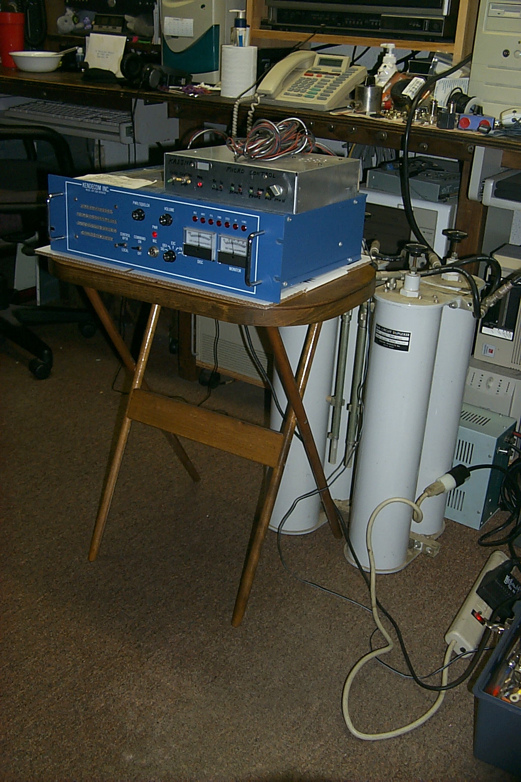
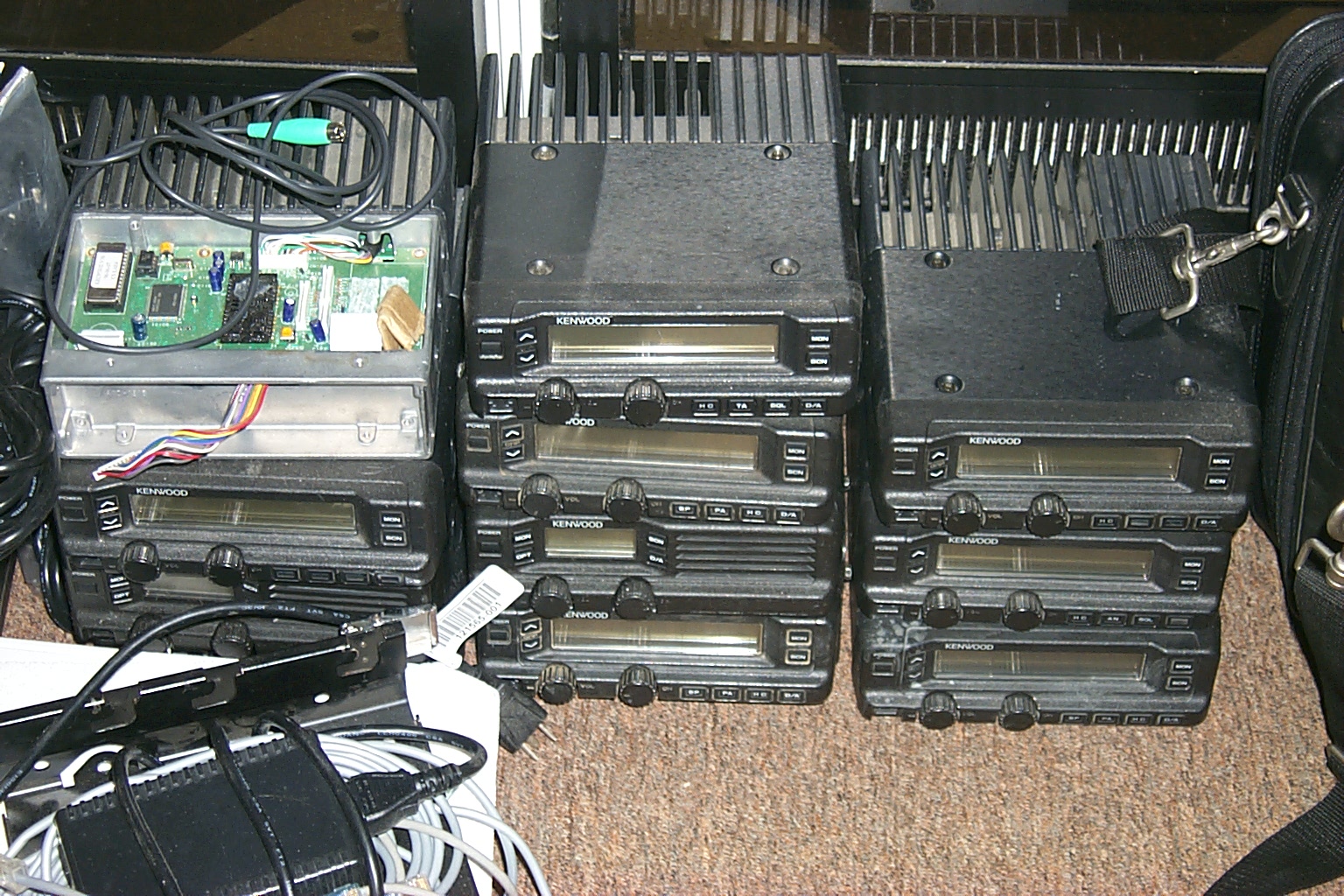
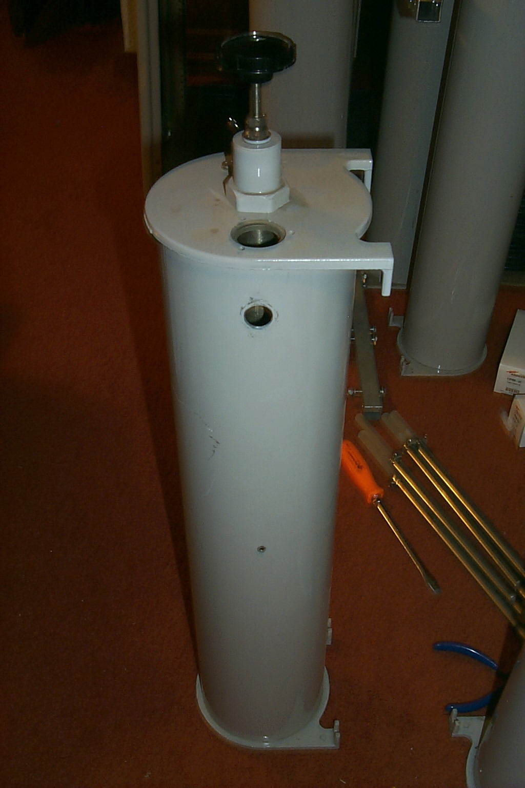
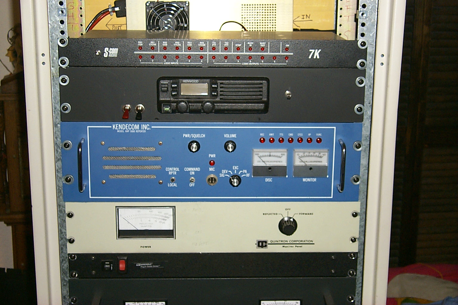
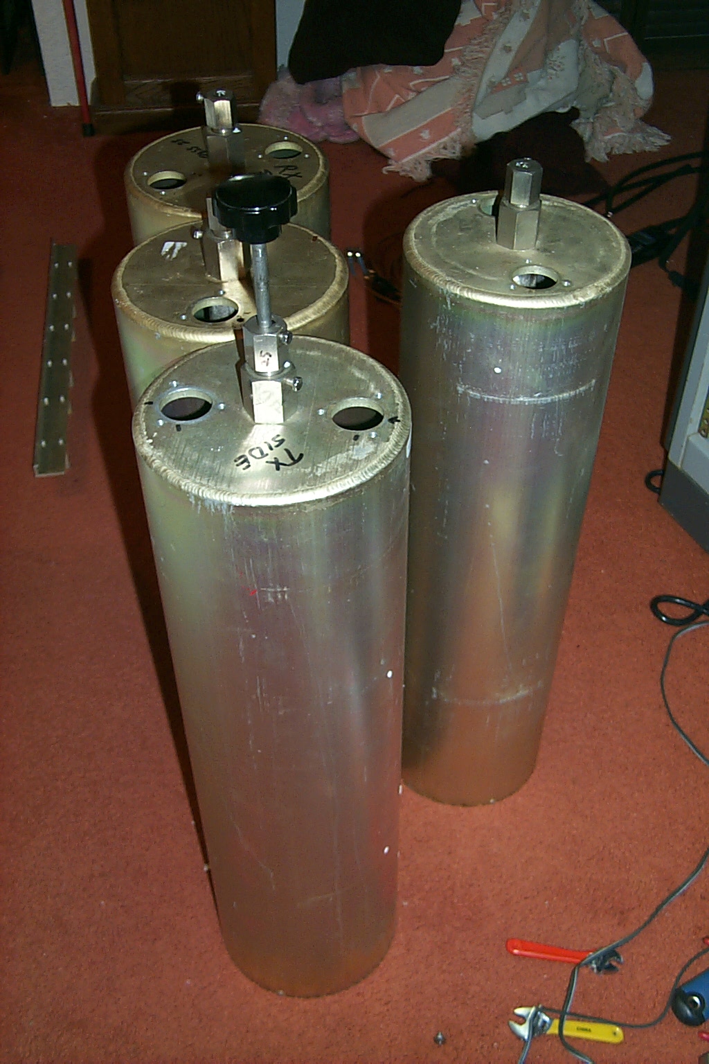
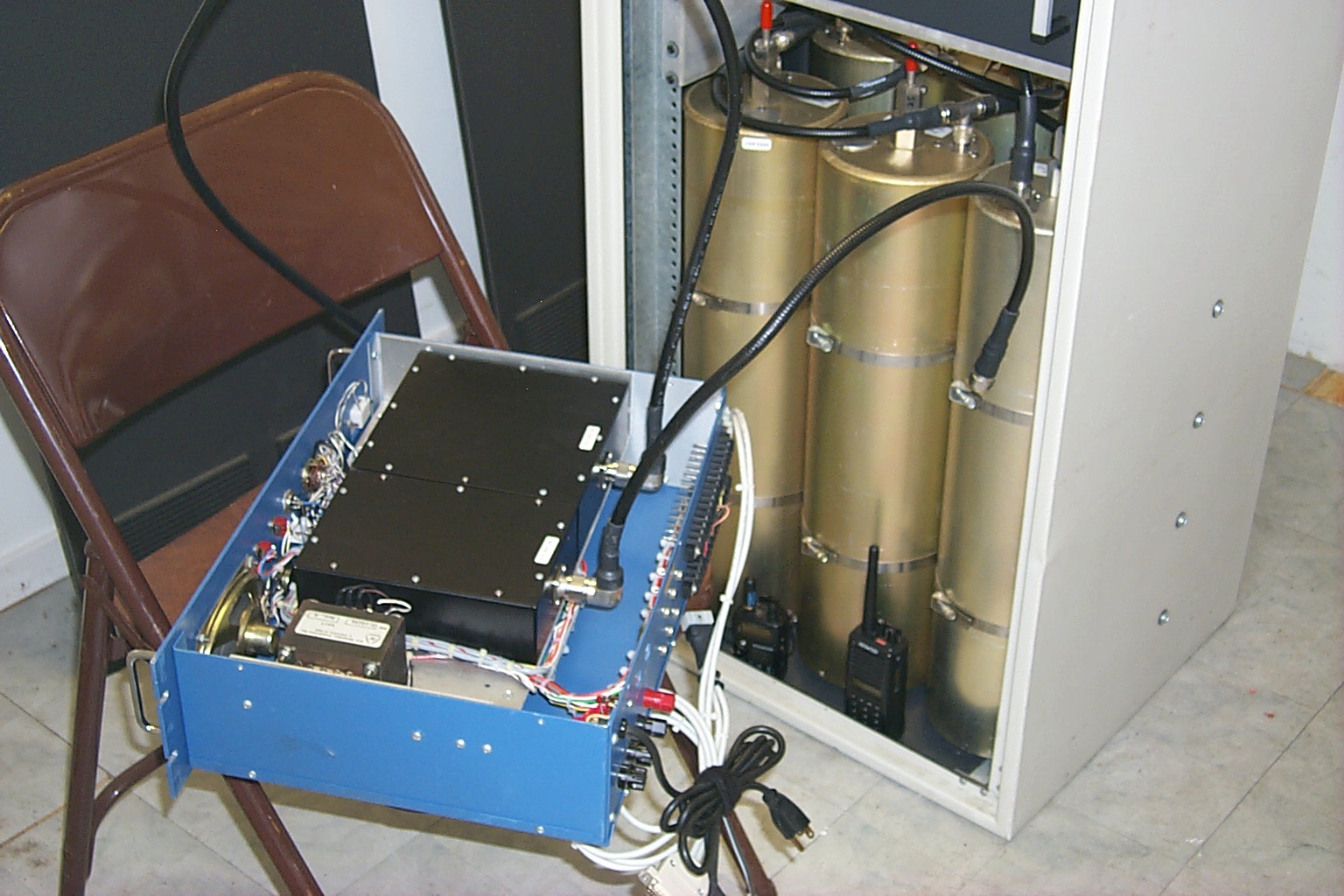
On the air in Lincoln for testing...
I had to wait for Sandy to head into the Zoo for the day and then when the coast was clear I dragged all of Bill's hardware into the radio room getting it setup so we could get the repeater back on the air and do some testing.
(click on images to enlarge)
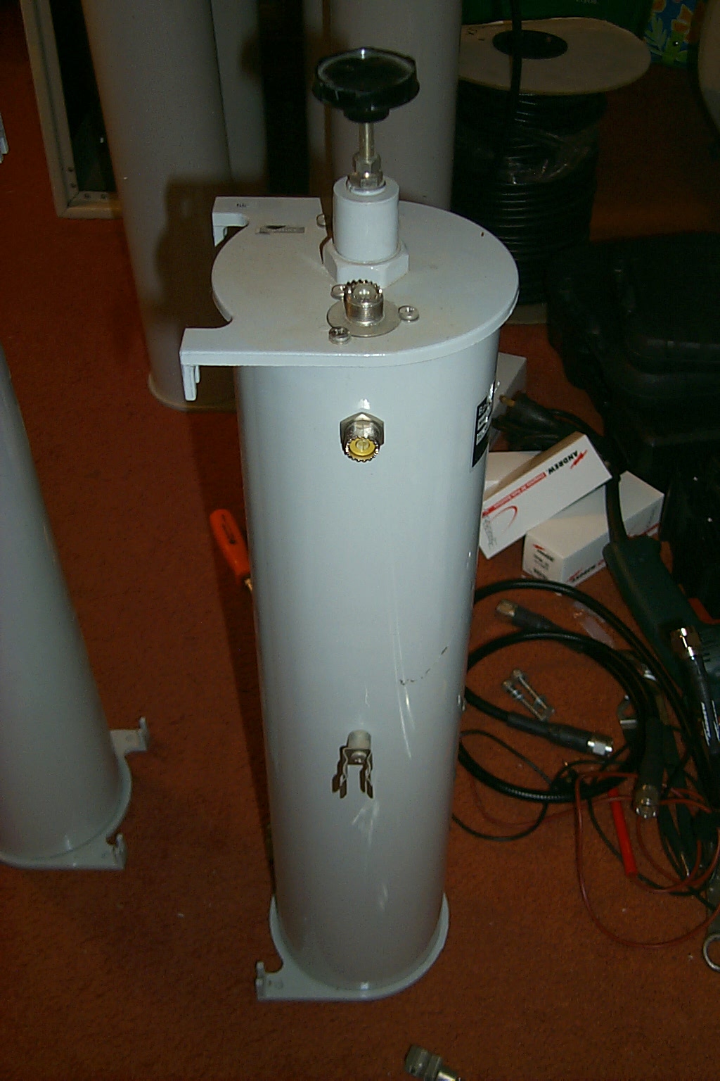
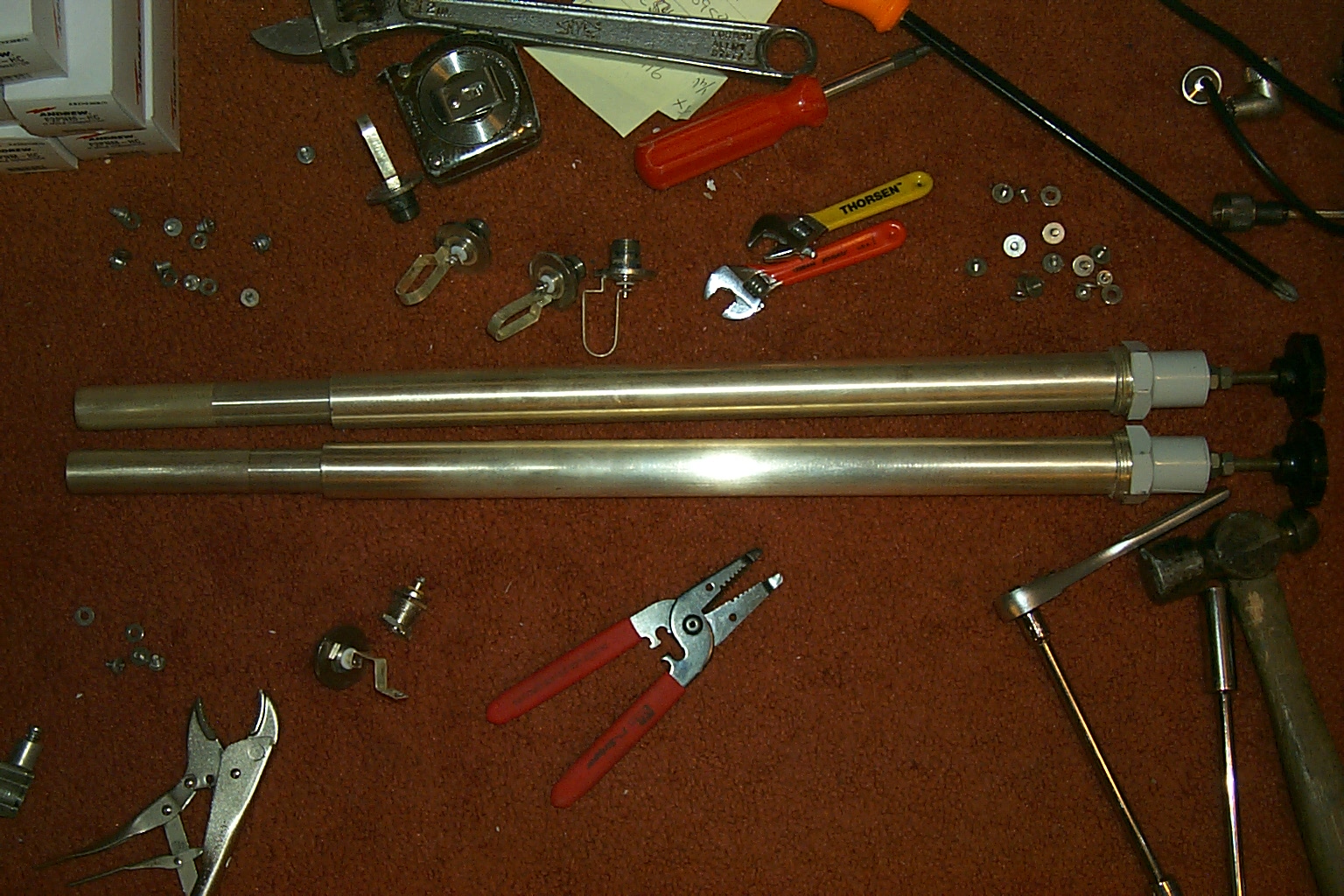
How about a UHF link radio?
My brother in law just finished making me three new custom mounts that allow me to rack mount the Kenwood TK-30 series radios and I just picked up a bunch of TK-730 and TK-830 radios that will be perfect for linking repeaters.
(click on images to enlarge)
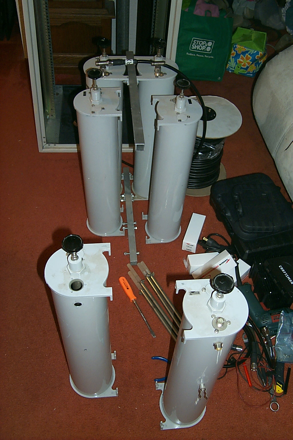
Ok ok... Stop complaining and do it already!
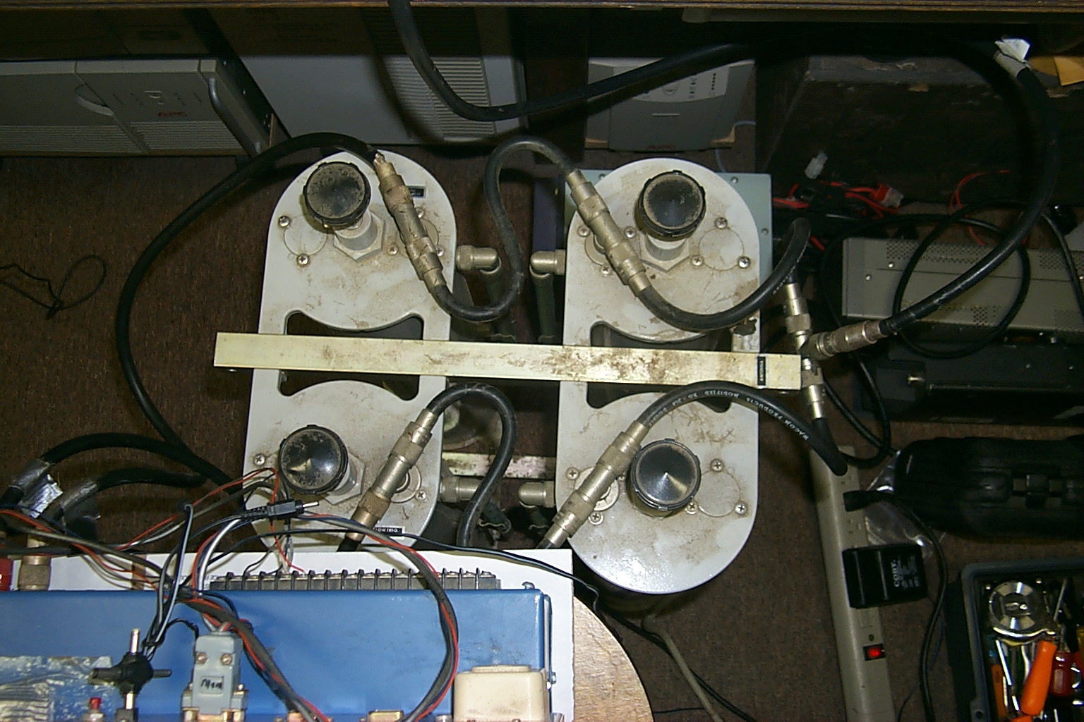
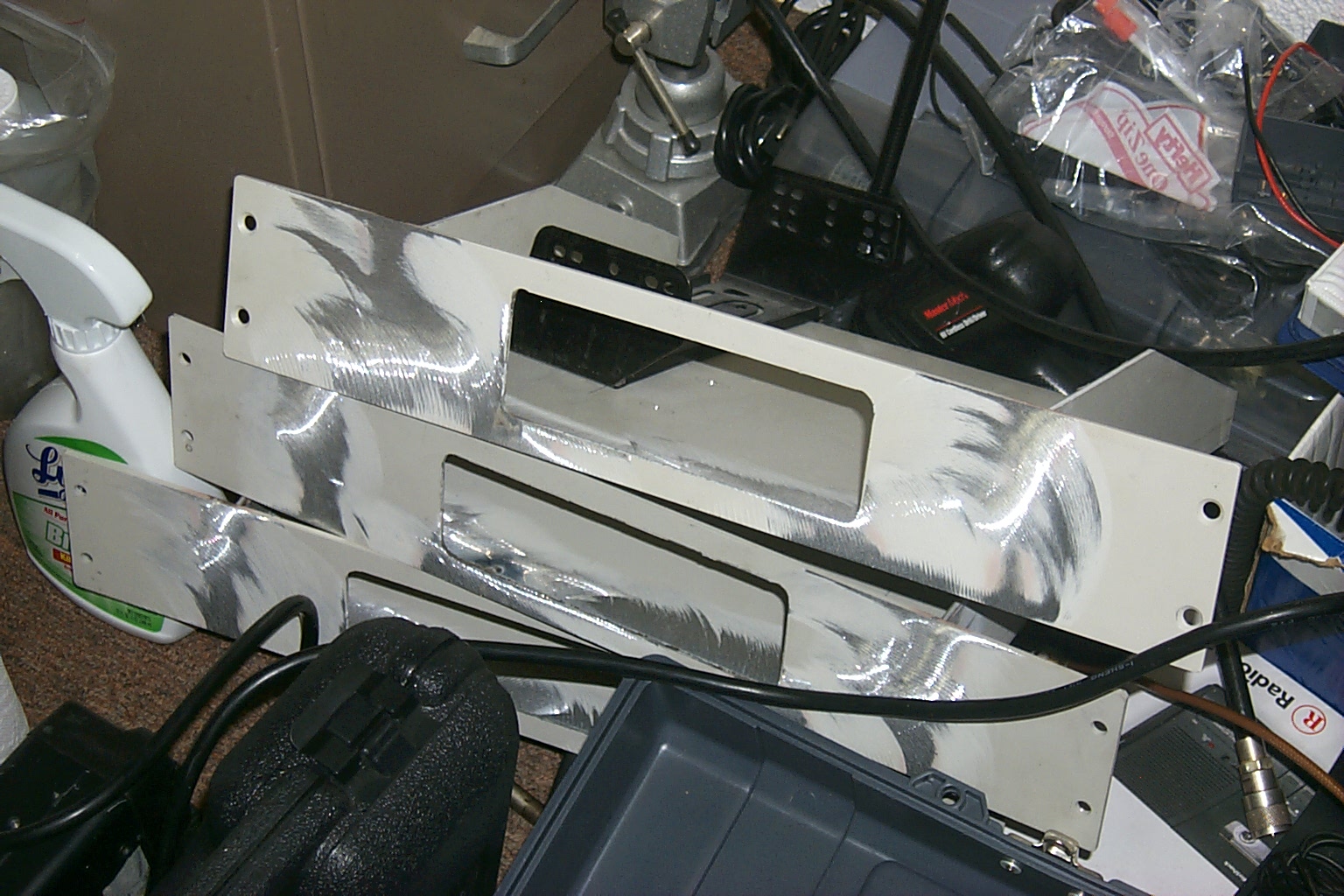
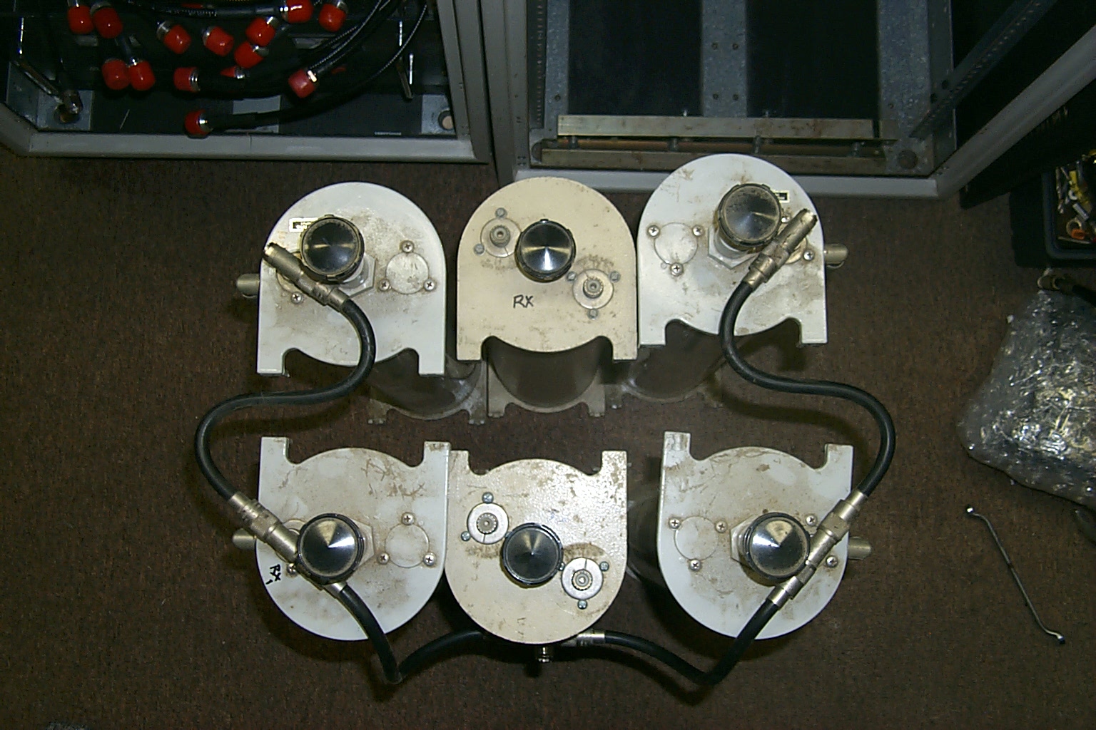
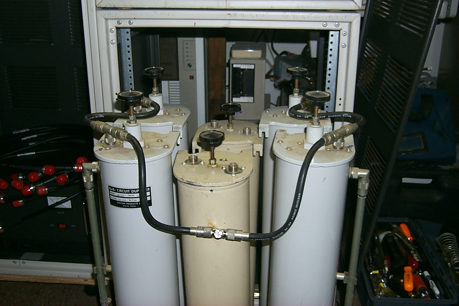
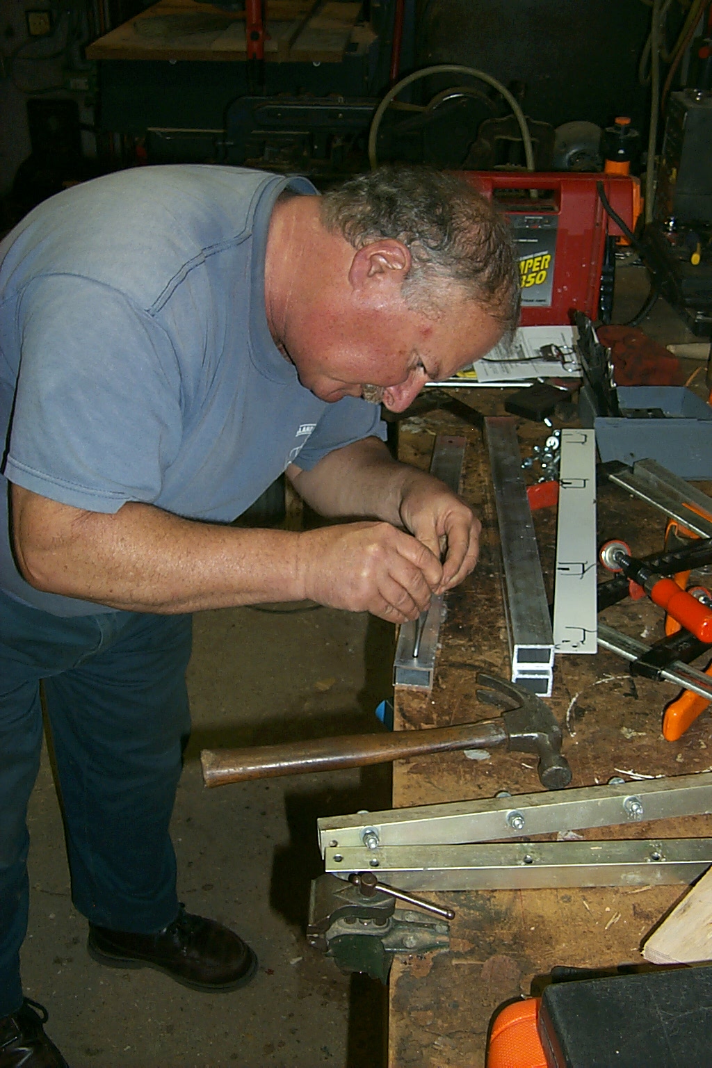
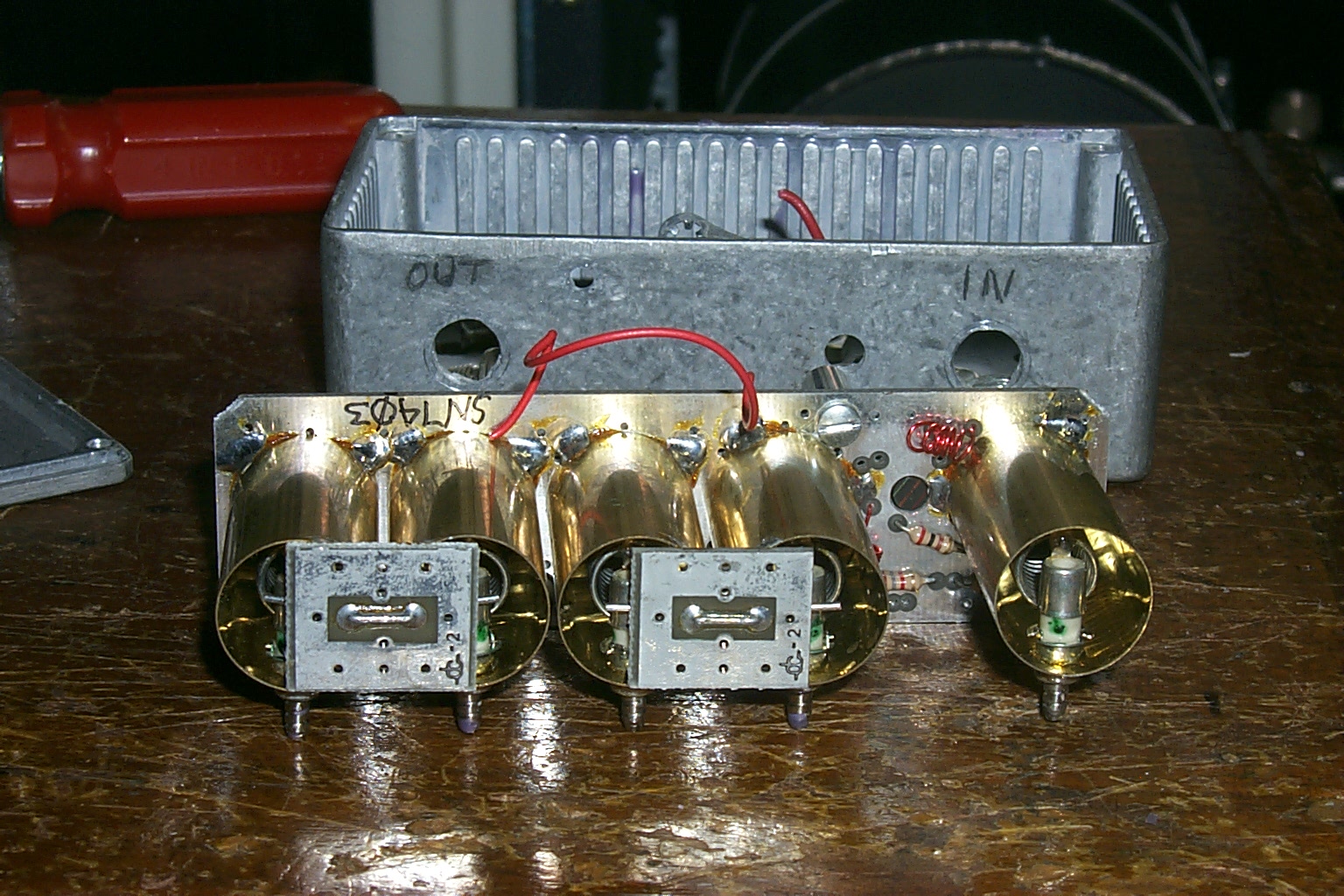
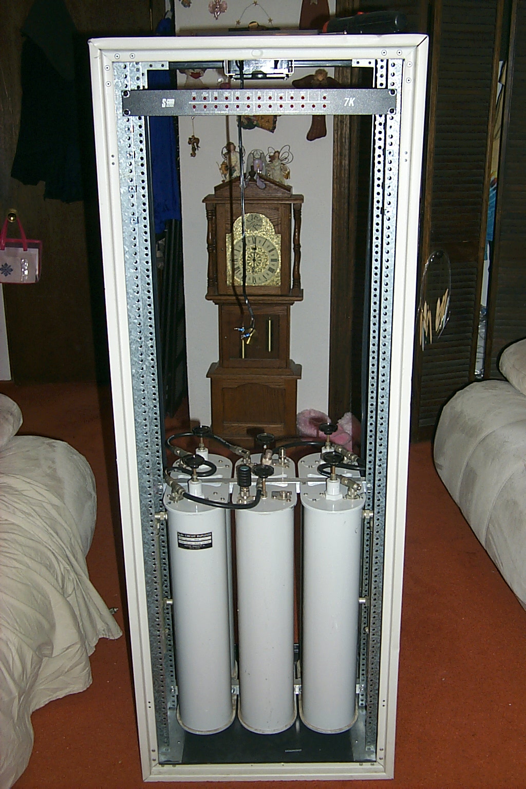
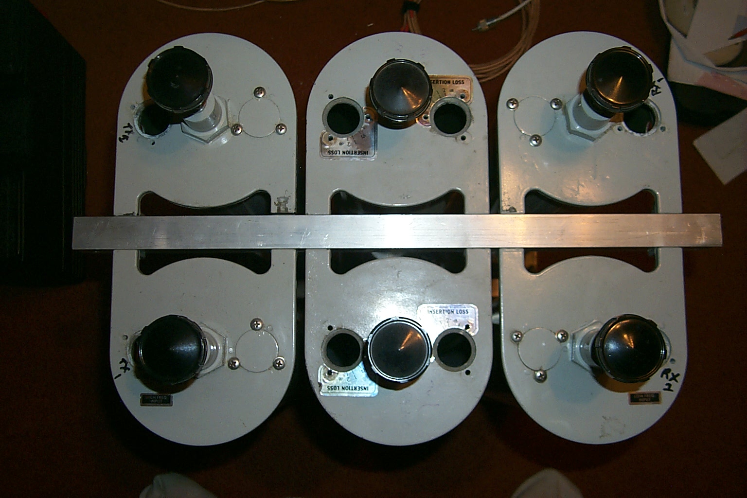
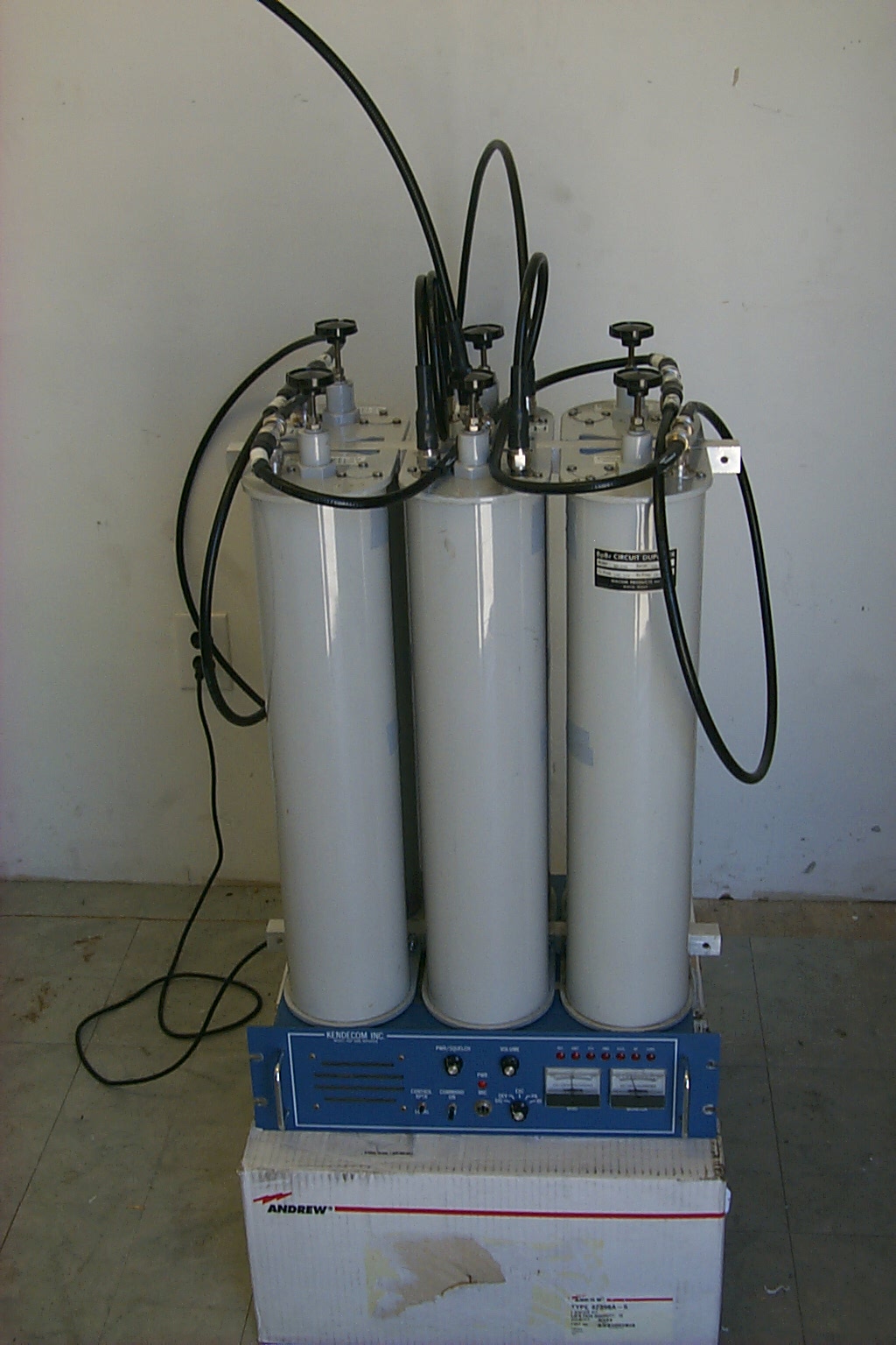
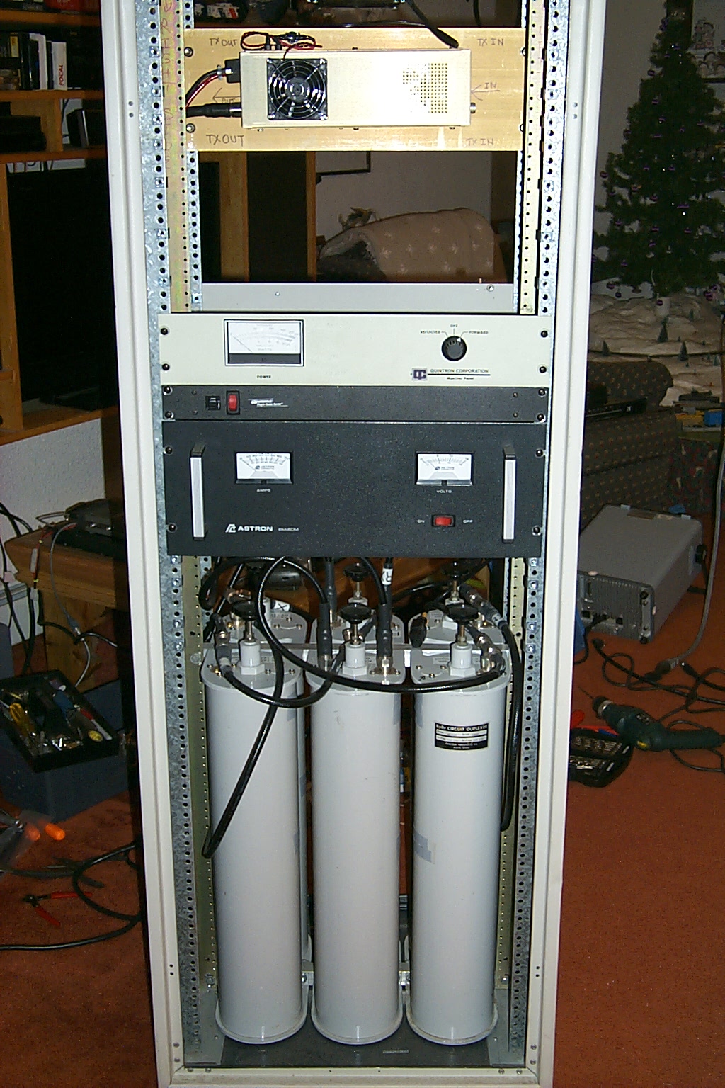
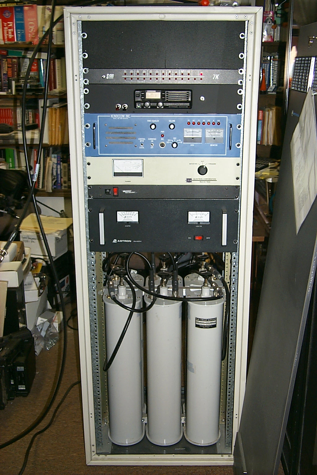
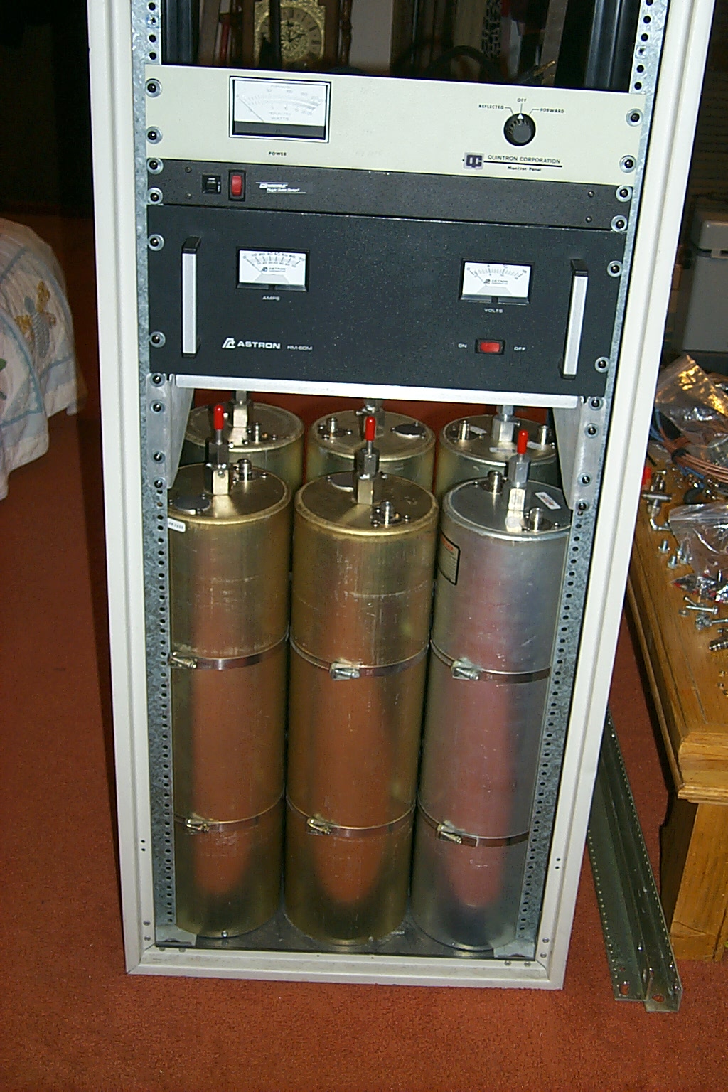
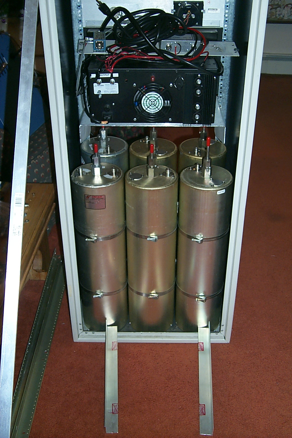
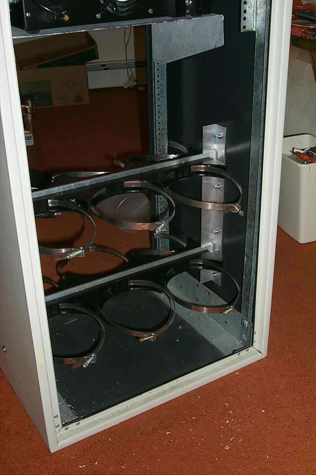
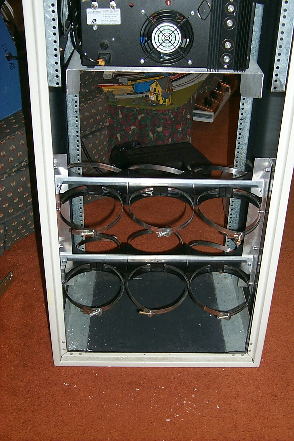
After a few days of testing Bills hardware here in Lincoln, and teasing Bill relentlessly, he finally broke down and told me to start the rebuild. I started off by making sure that I could fit the existing four cavity BP/BR duplexer and two additional band pass cavities into a 30 inch rack. Then I bolted on a second 30 inch rack for the rest of the hardware including a new AC power strip, power supply, Kendecom repeater, link radio, and S-Com 7K controller.
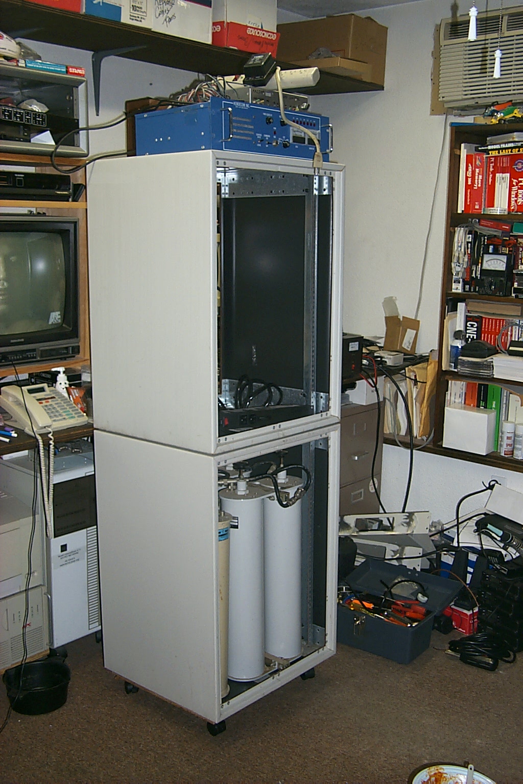
(click on images to enlarge)
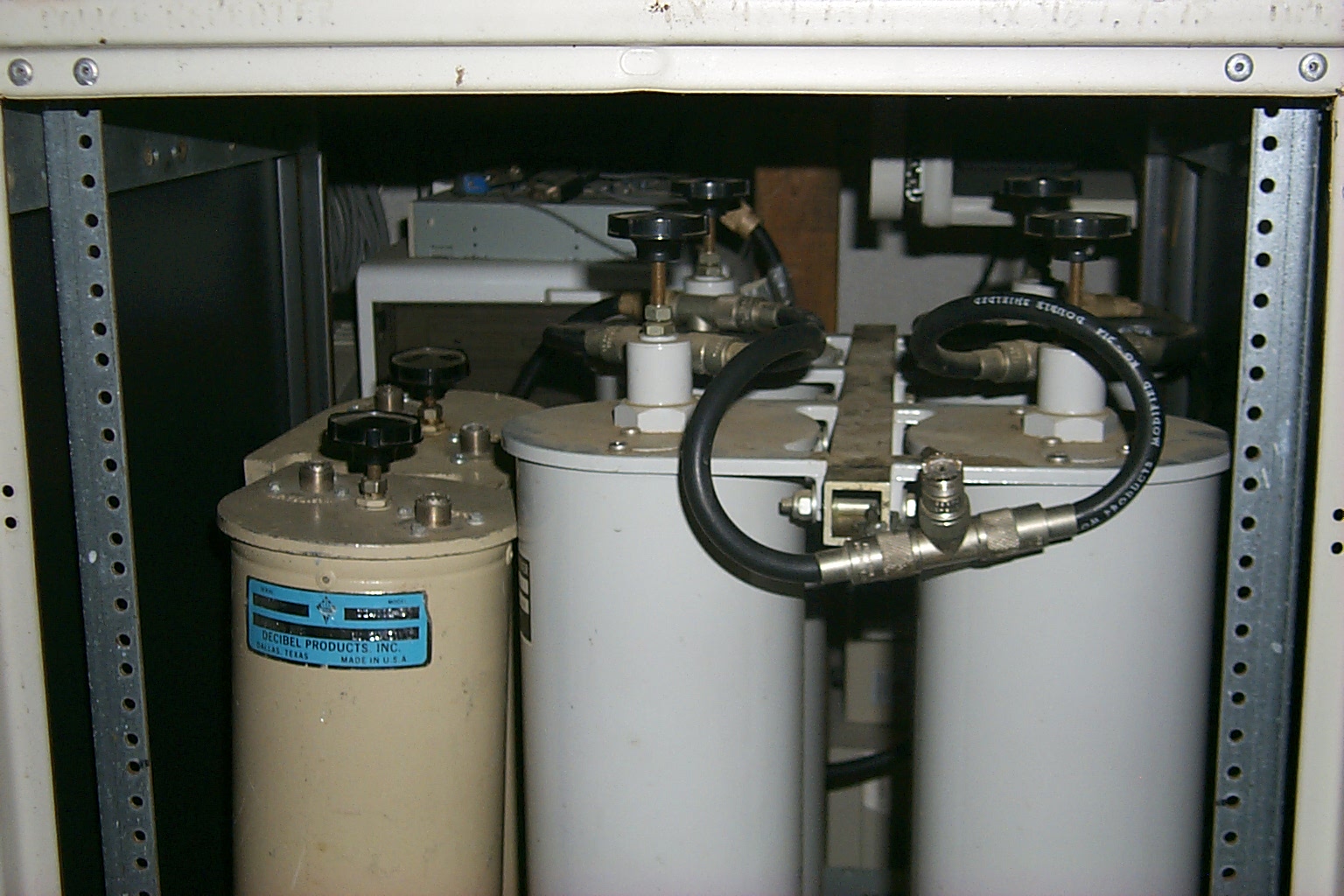
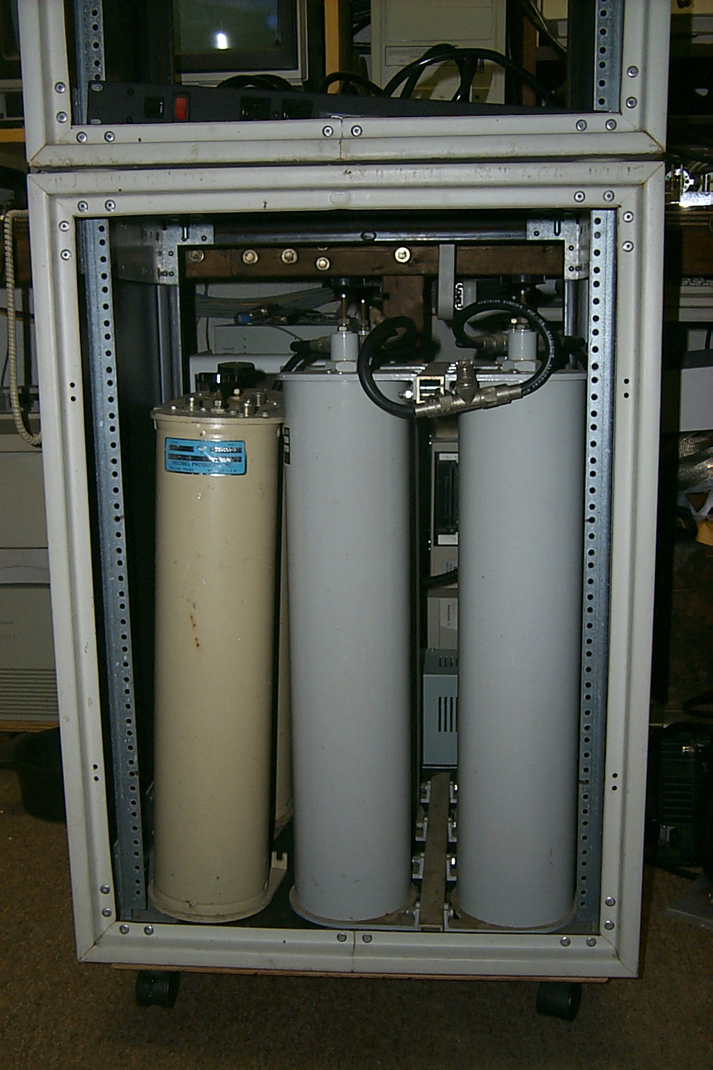
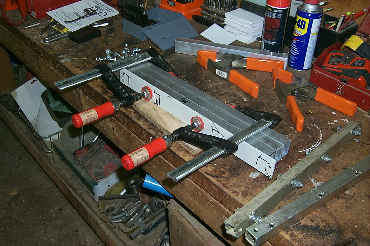
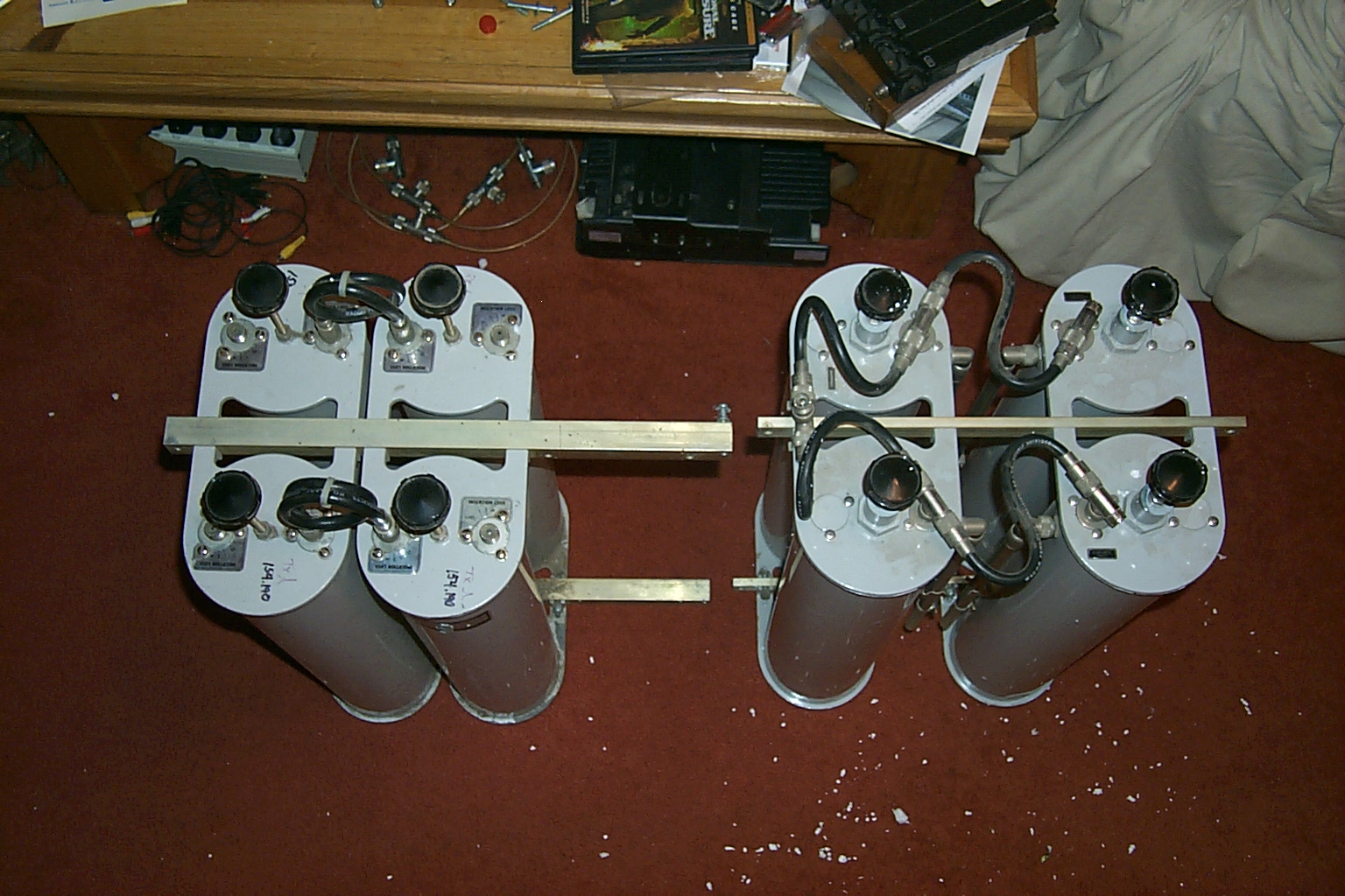
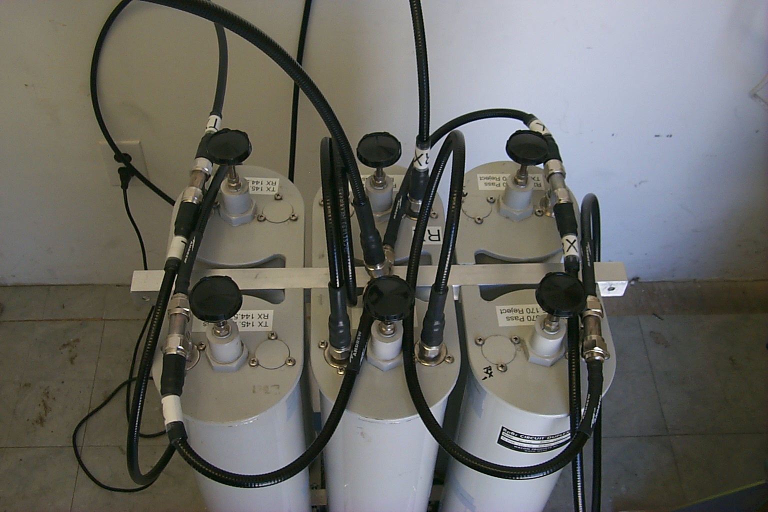
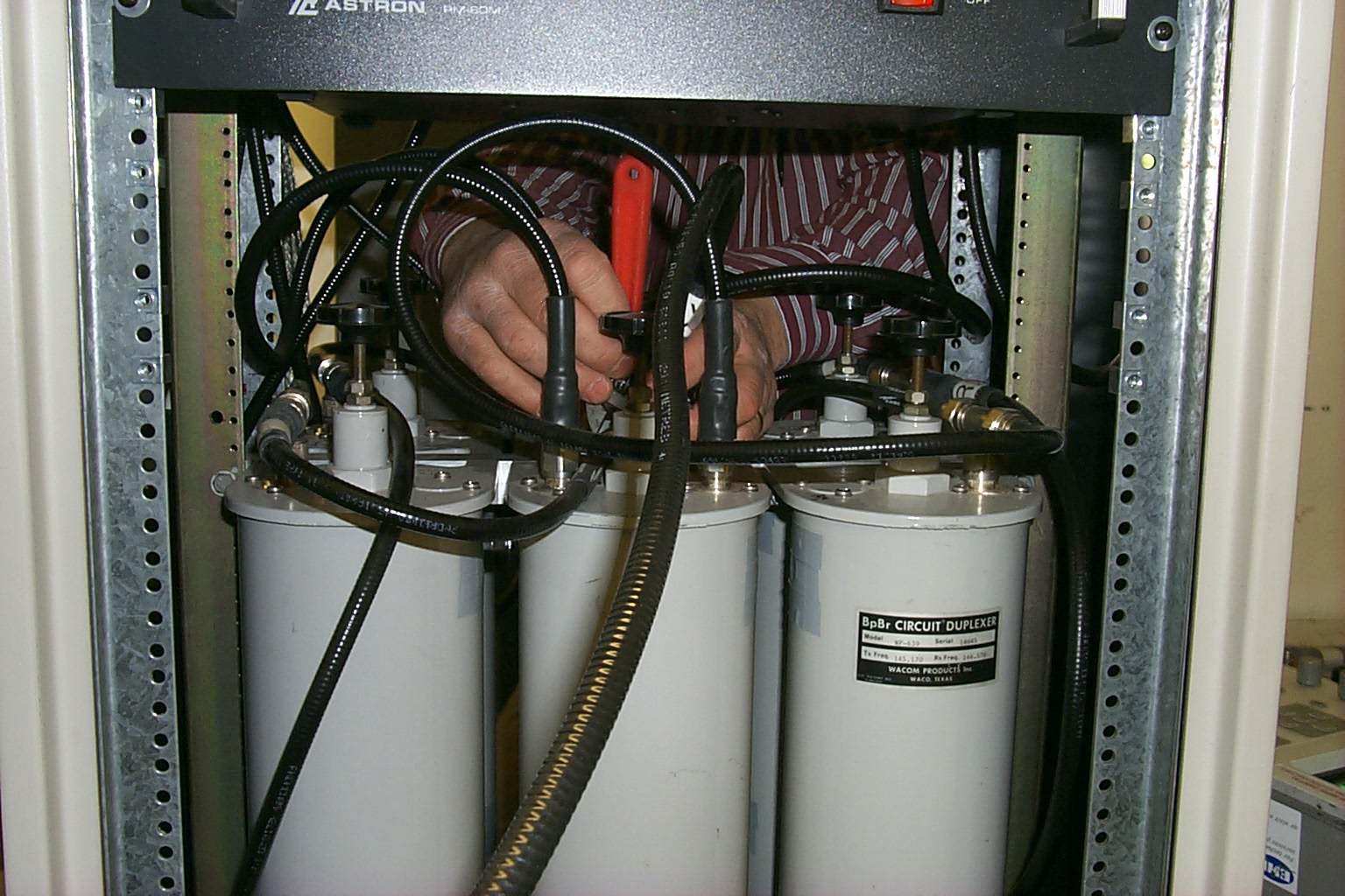
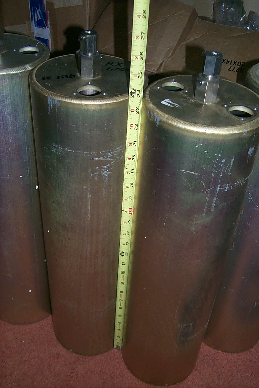
Stop man handling my cans...
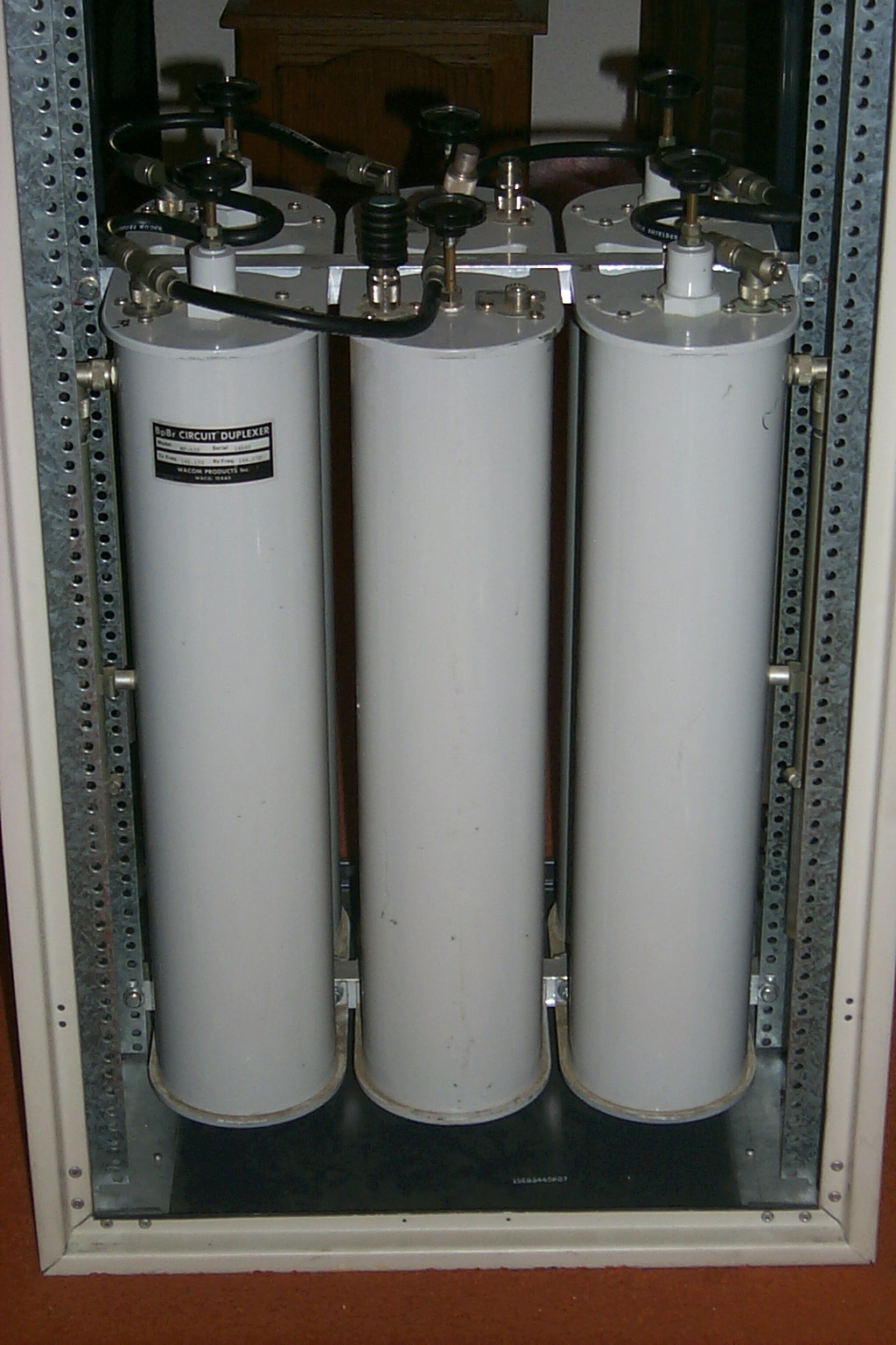
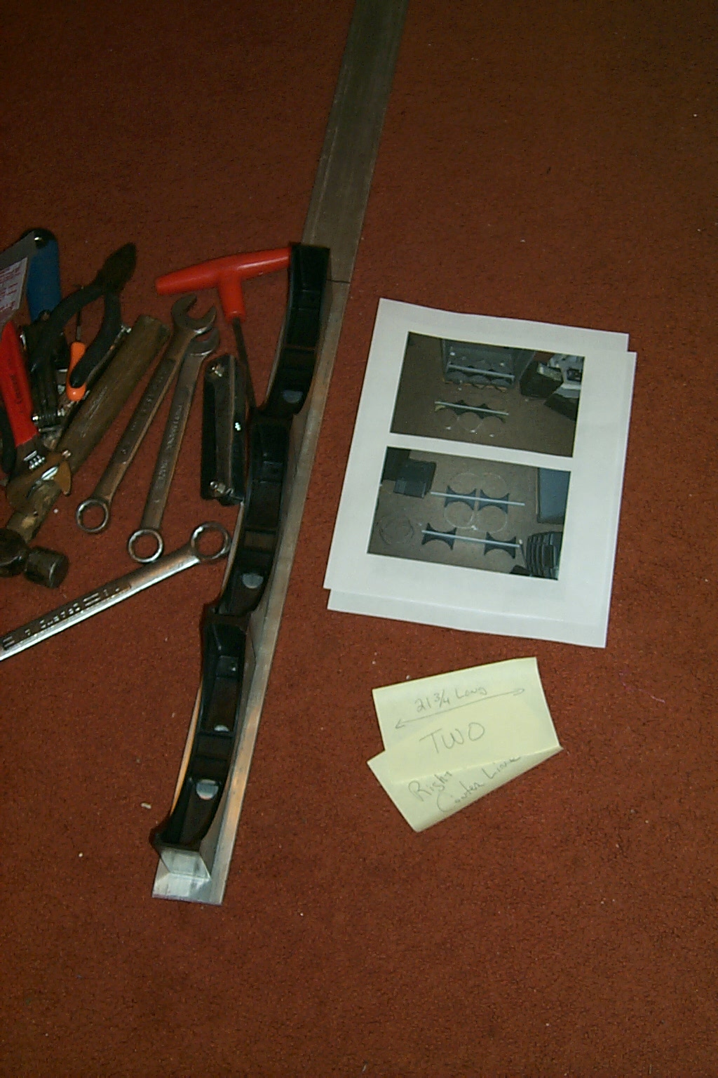
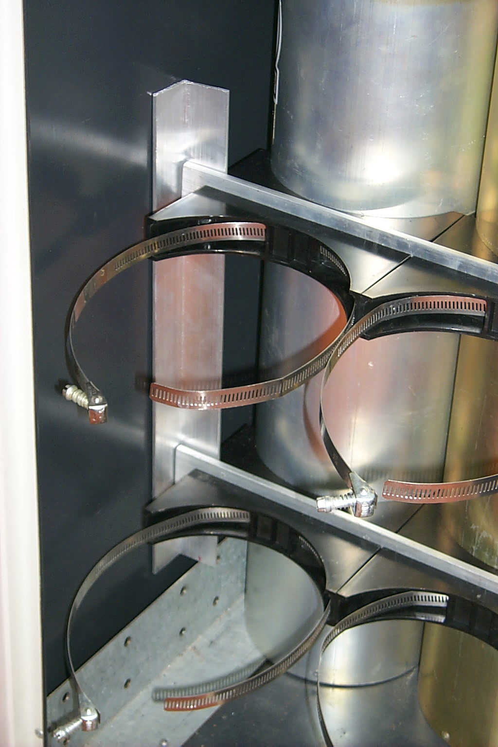
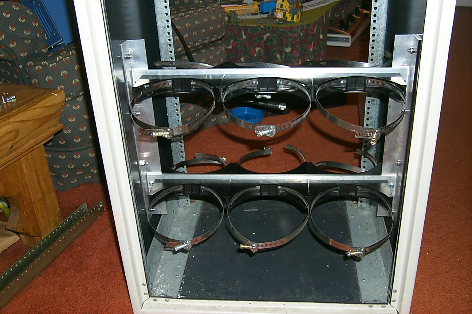
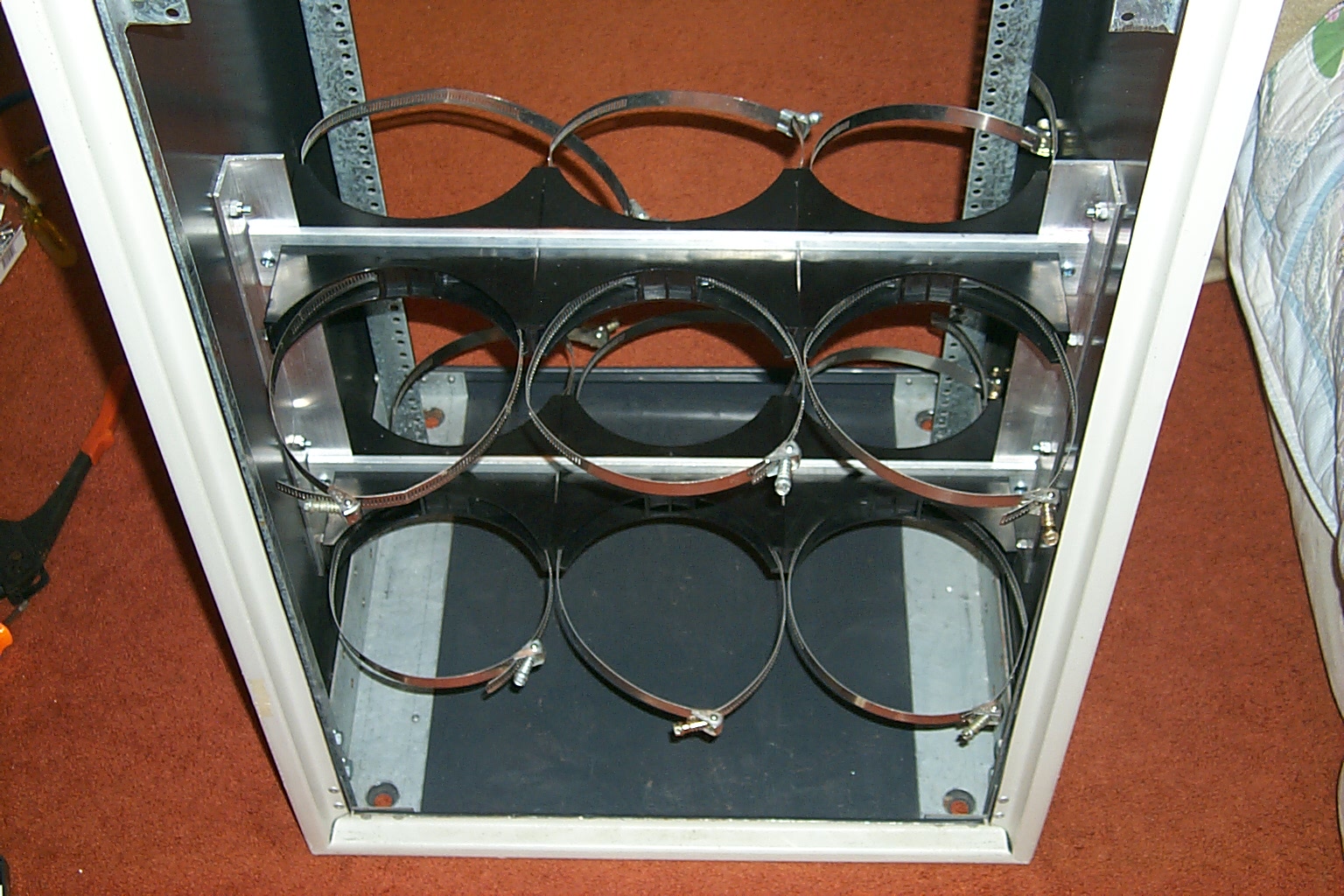
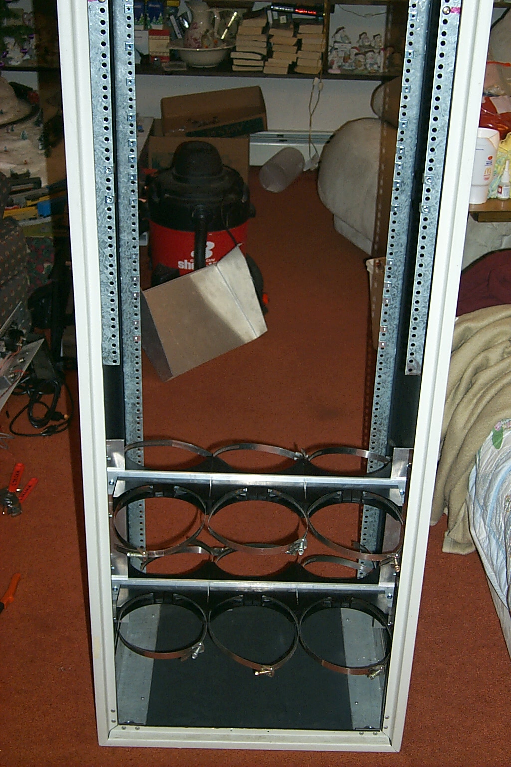
I had great deal of fun teasing Billy about how Bruce KD1BE and I were beating the crap out of his duplexer cavities but it was all just in fun. I had mocked up the duplexer to make sure that I could squeeze all six cans into the bottom 30 inch rack cabinet then started gathering all the hardware and materials needed to fabricate new custom mounting rails to support all six cans properly in the standard 19 inch rack mounts.
Syl N1DKF had located a dealer online that I could purchase some 1 inch by 1-1/2 square aluminum tubing from and I sent Sandy to the hardware store to purchase a dozen bolts, washers, and nuts the appropriate size to fasten everything together. Once the 6 foot section of aluminum tubing arrive I measured the space inside the rack cabinet and decided that 19-3/4 inches was the correct length for the new duplexer mounting rails.
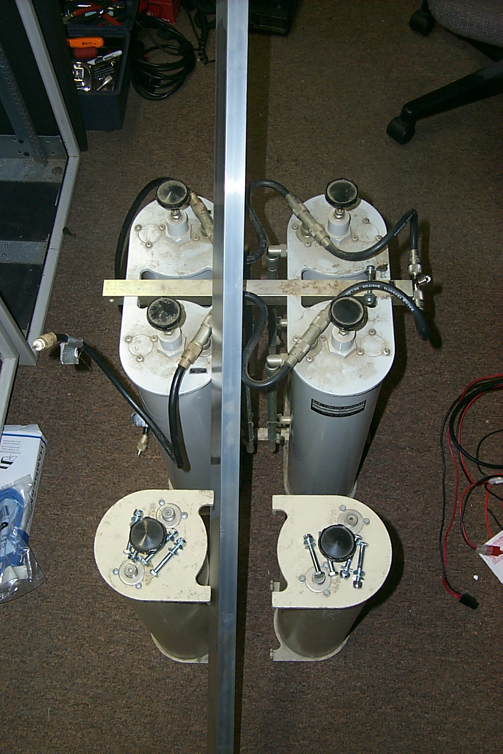
(click on images to enlarge)
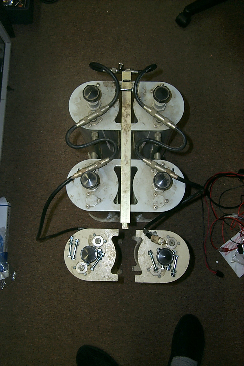
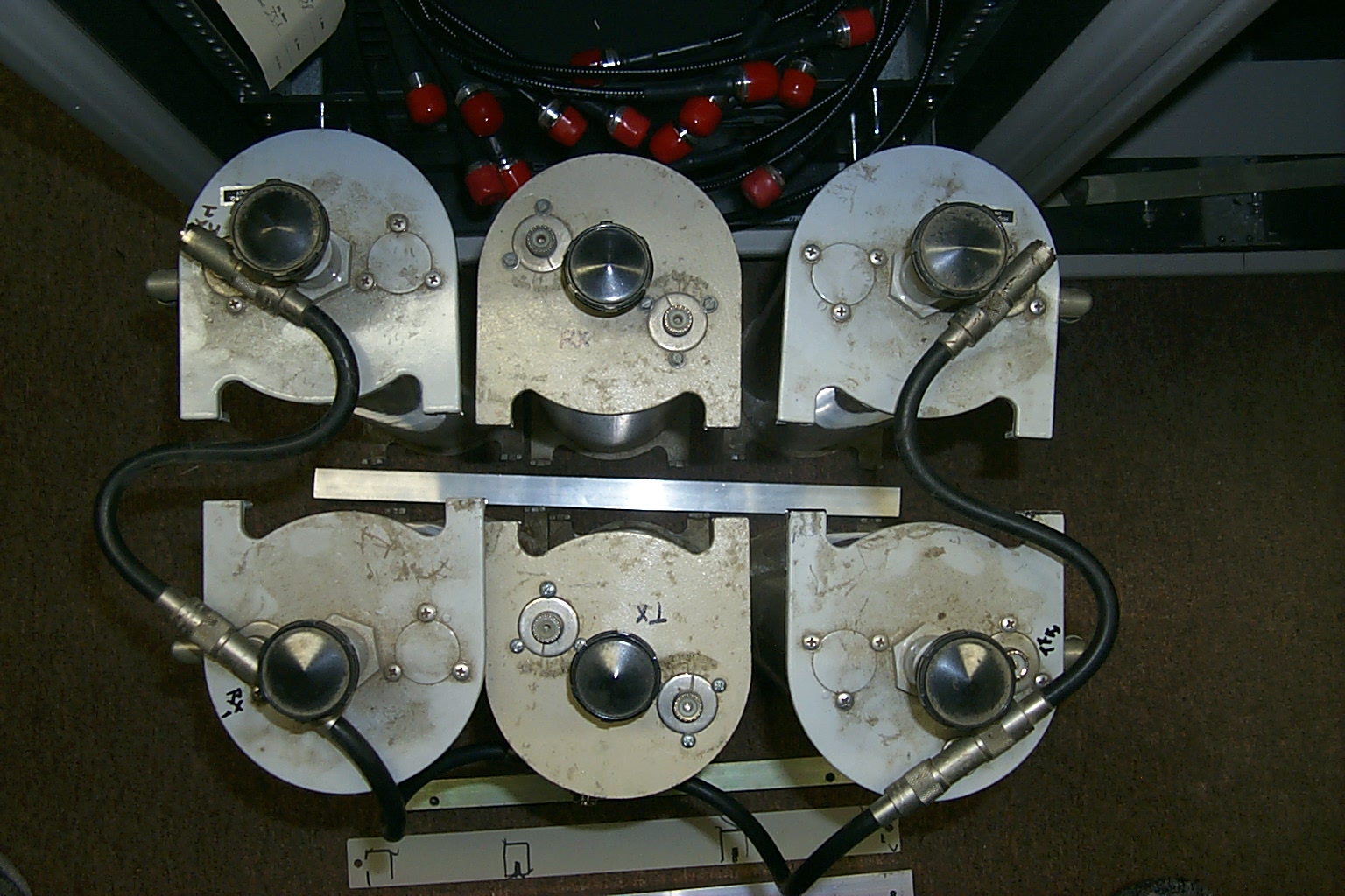
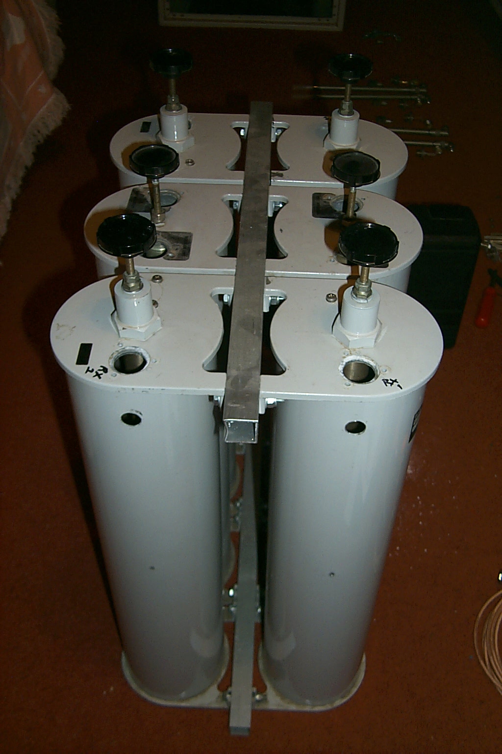
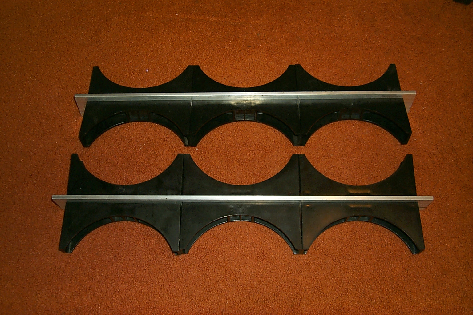
After some checking and measurements I realized that I could not get the cavities close enough together so they would all fit into the limited space available because to the external band reject adjustment tubes. I would have to rearrange the position of the cavities, placing the two additional band pass cavities in the middle of the original band-pass / band-reject cavities, with the reject adjustment tubes located on the outside four corners of the new duplexer arrangement.
(click on images to enlarge)
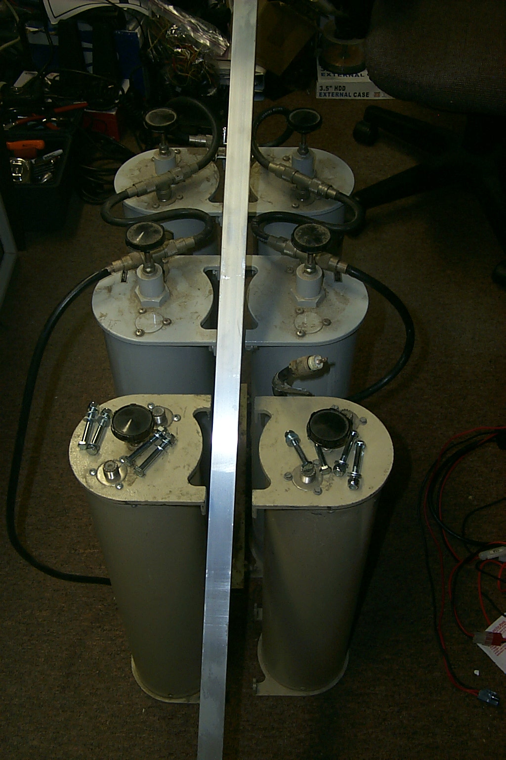
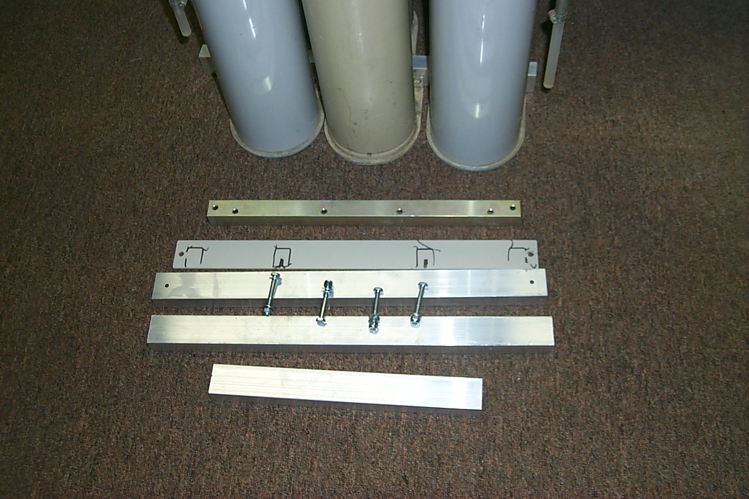
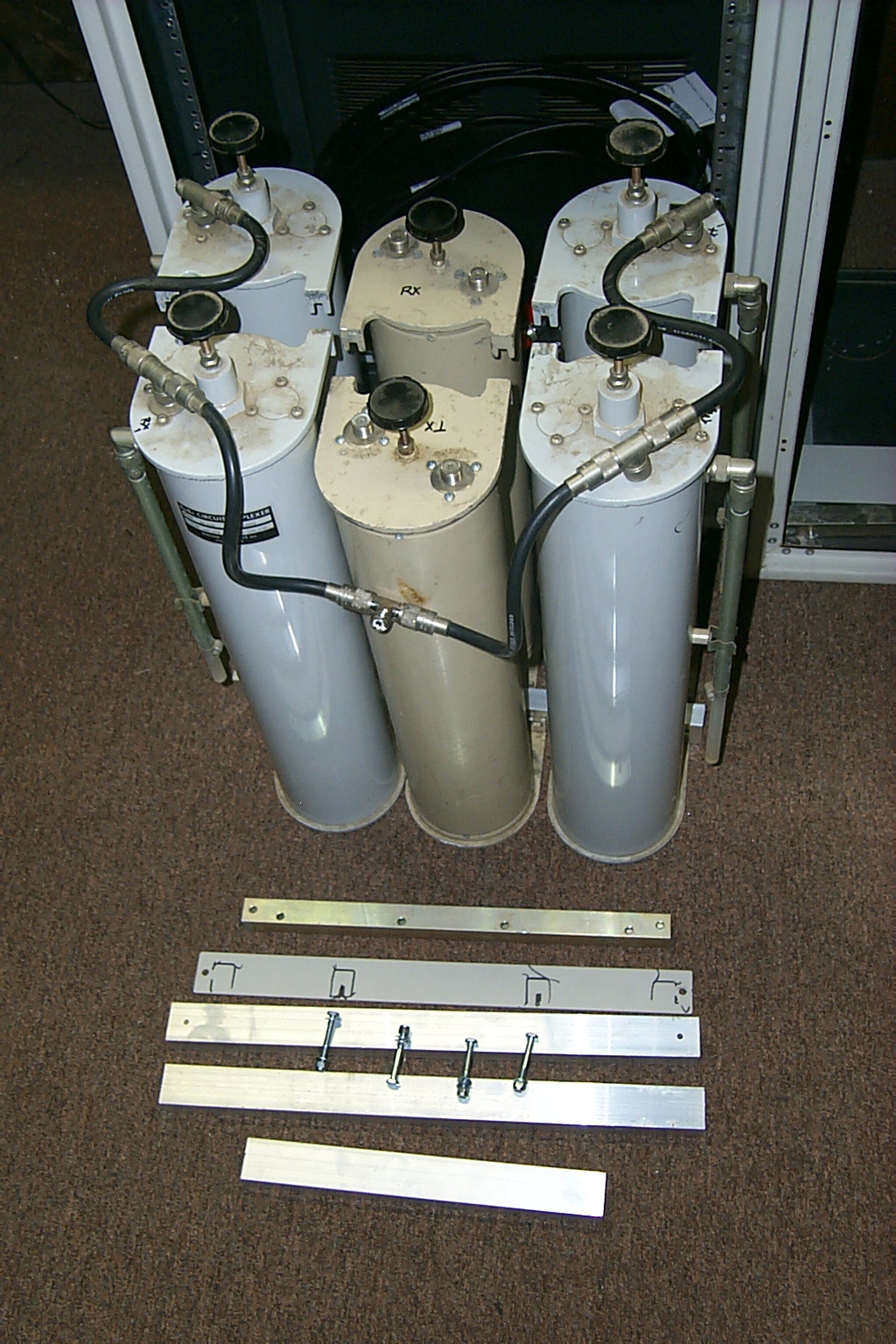
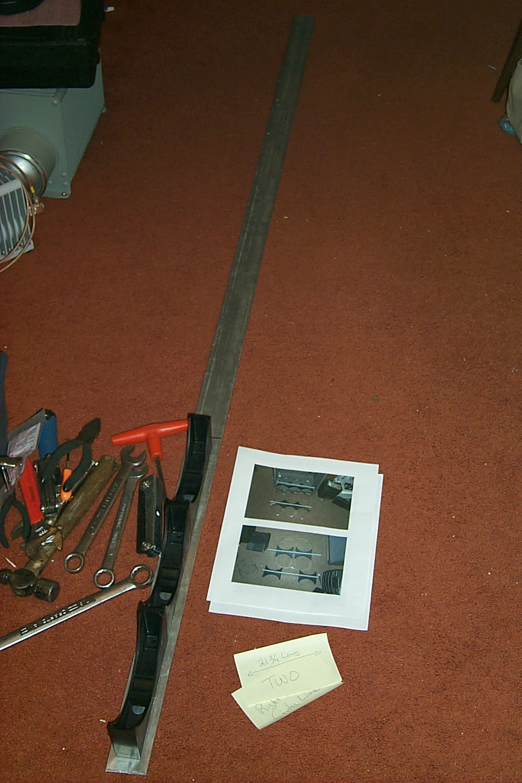
Next I had Sandy take the section of tubing to her brothers shop and he cut them down to the three 19-3/4 inch sections that I needed to make the new mounting rails.
(click on images to enlarge)
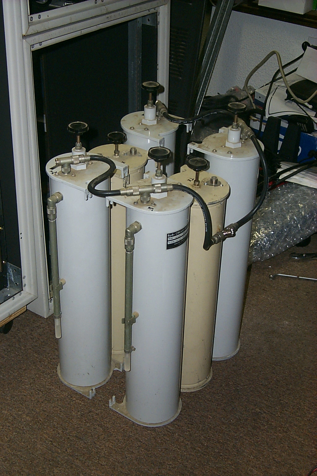
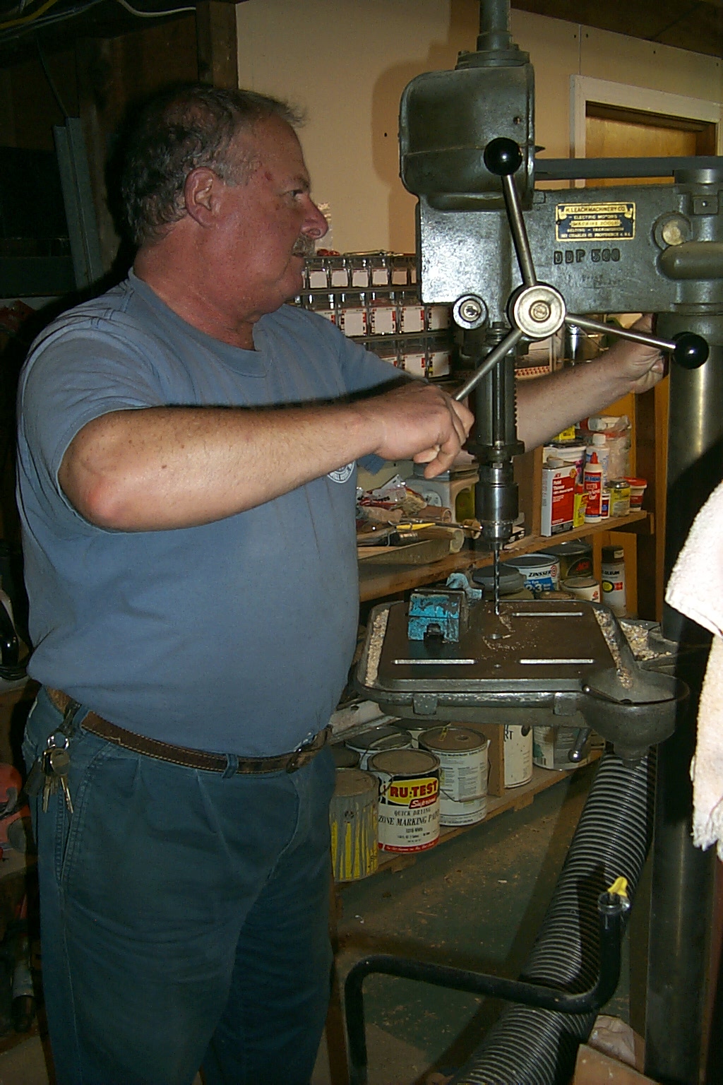
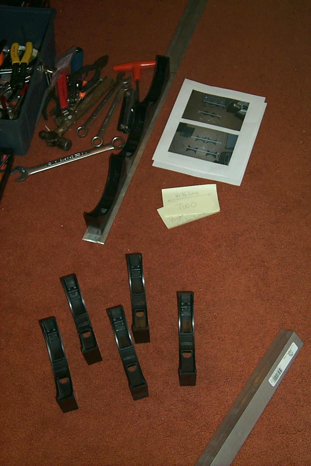
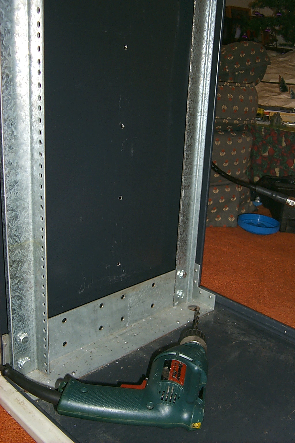
Let the drilling begin...
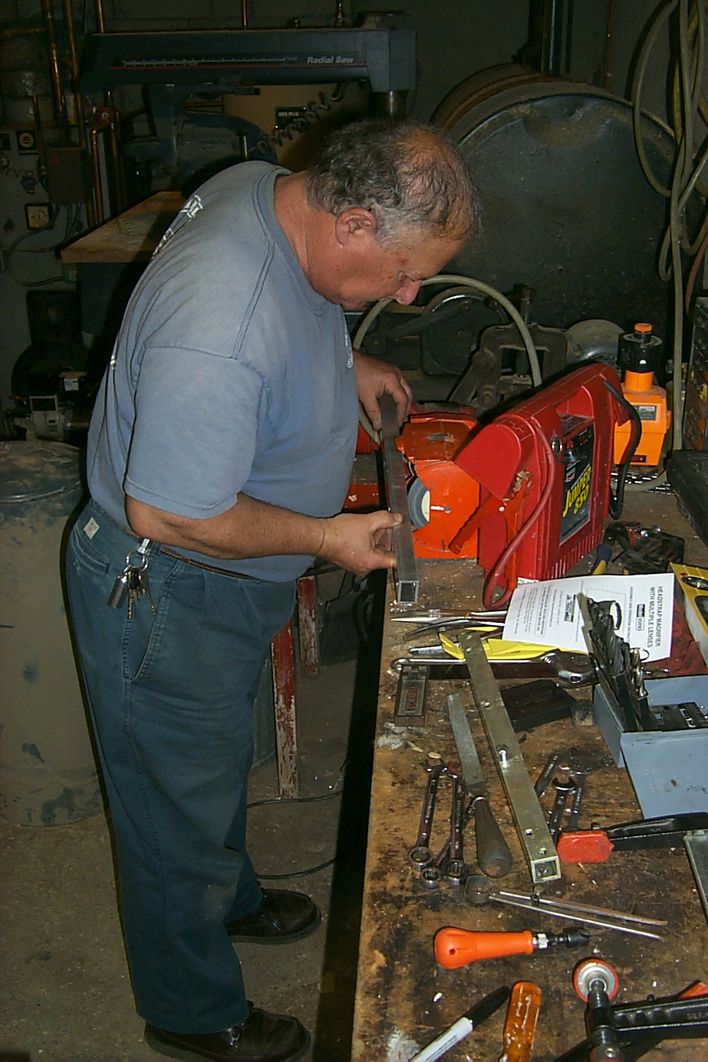
Once I has the three sections of tubing, along with all the other hardware, I packed everything up and dragged it over to Bruce KD1BE's shop so we could measure and drill all the holes for the cavity mounting. We would also have to drill out the holes for mounting in the duplexer into the 19 inch rack cabinet rails. Bruce carefully transferred all of the measurements that I had made, while mocking up the cavity placement in the rack cabinet, to the new aluminum tubing and one by one he started drilling the holes.
(click on images to enlarge)
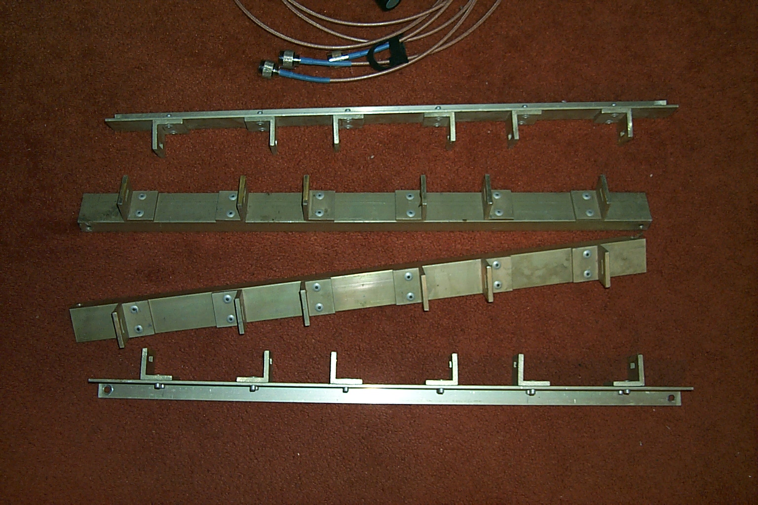
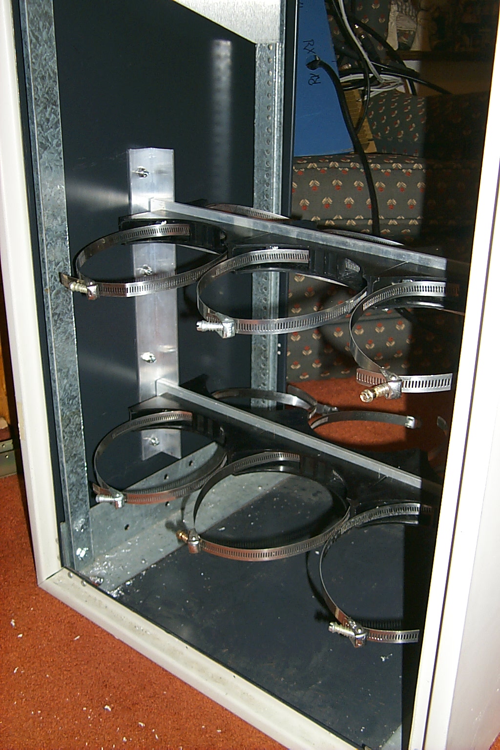
With the hole drilled in the first of the new mounting rails for the two original cavities placed to the outside we were able to secure those cans to the top mounting rail and then measure for the placement of the two additional cavities in the center. Once we had those measurements we finished the top rail and it was very easy to use that as a template to drill all the holes on the bottom rail.
(click on images to enlarge)
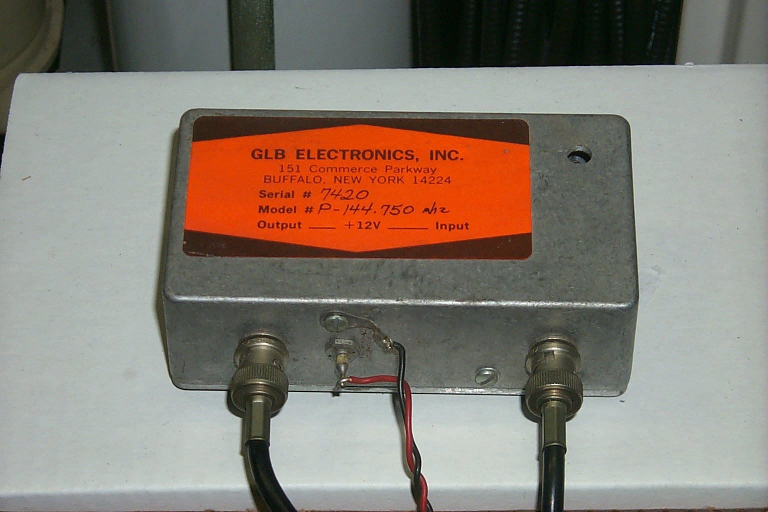
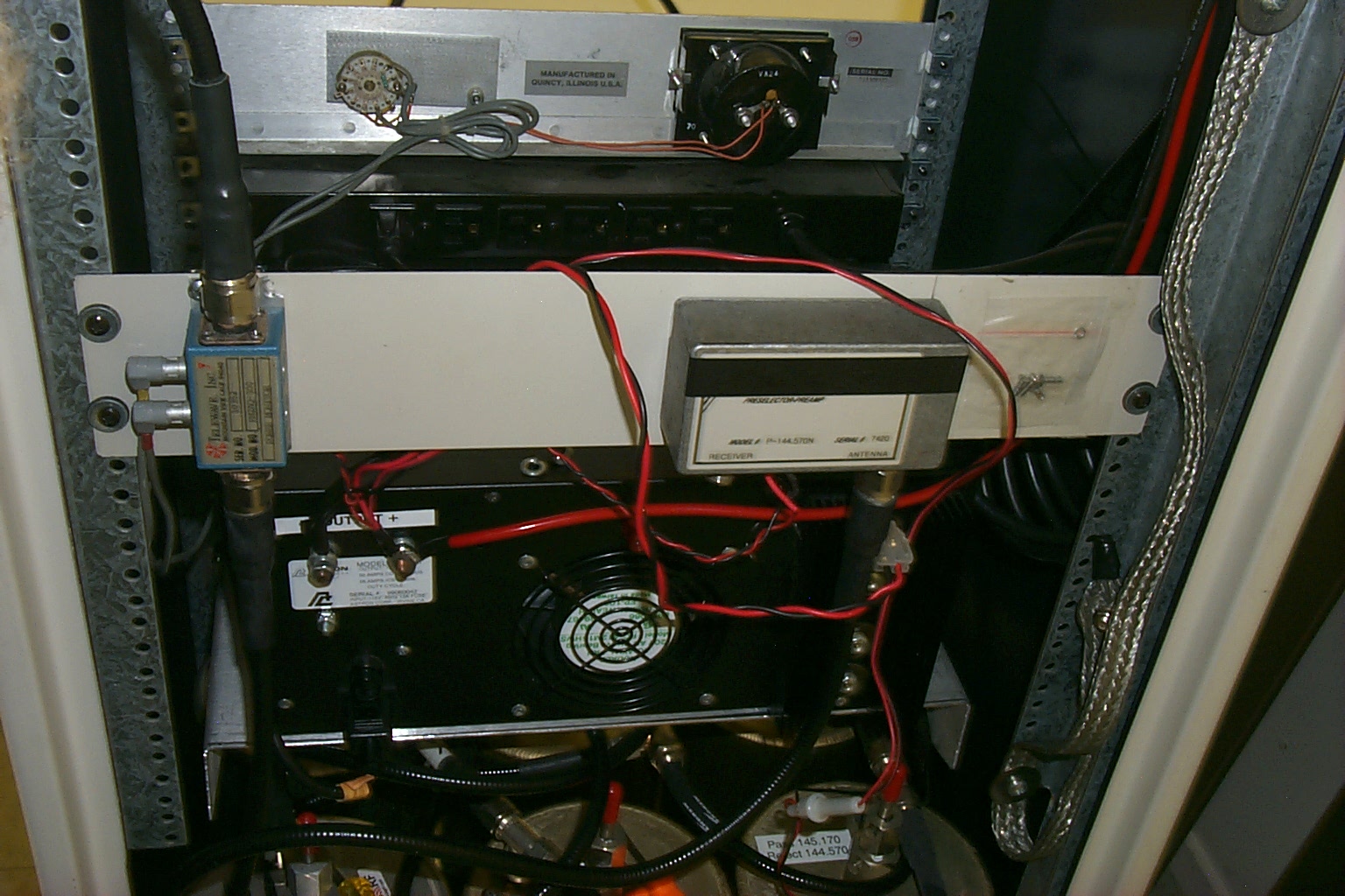
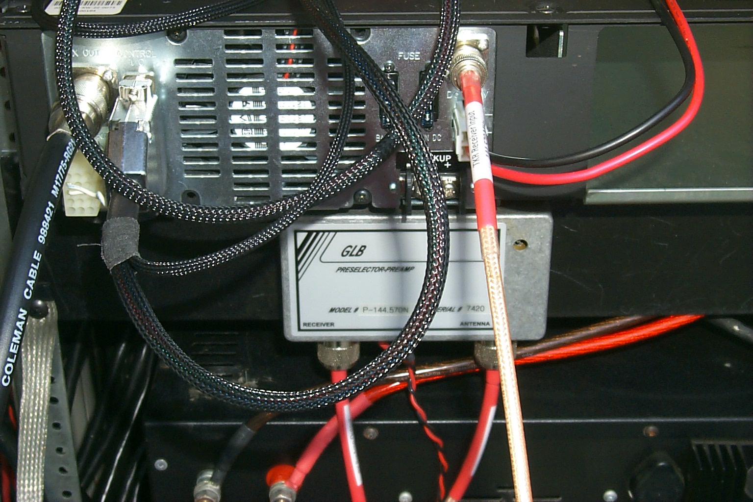
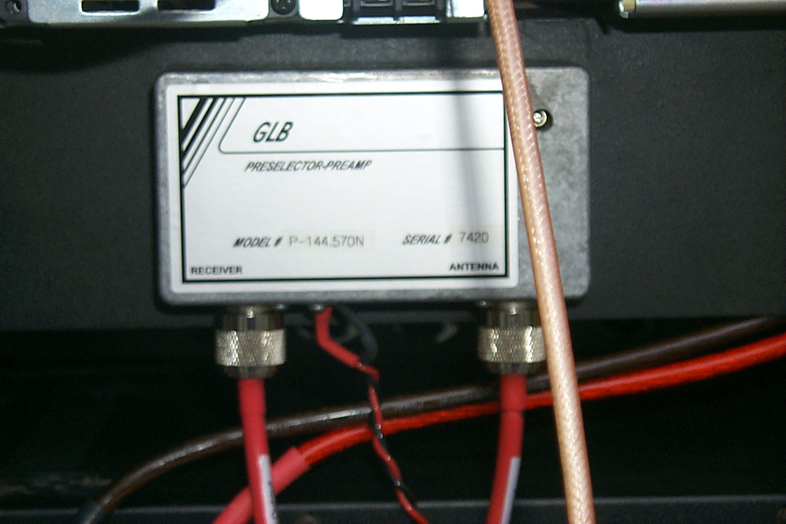
I started rebuilding all the hardware back into the two 30 cabinets that were bolted together. Brian N1BS also donated a GLB PreSelector / PreAmplifier from the 145.350 repeater to use on this project that I would upgrade and re-tune for the 145.170 repeater.
(click on images to enlarge)
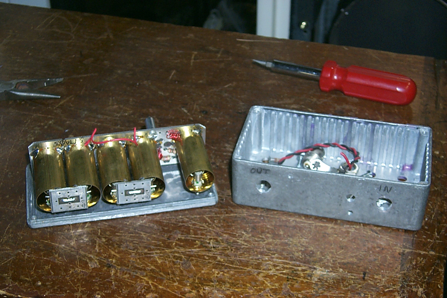
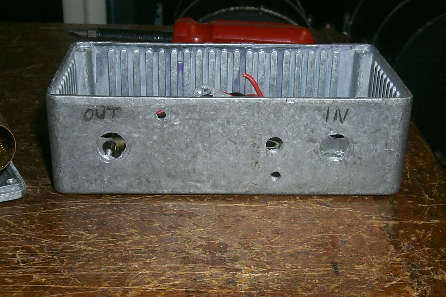
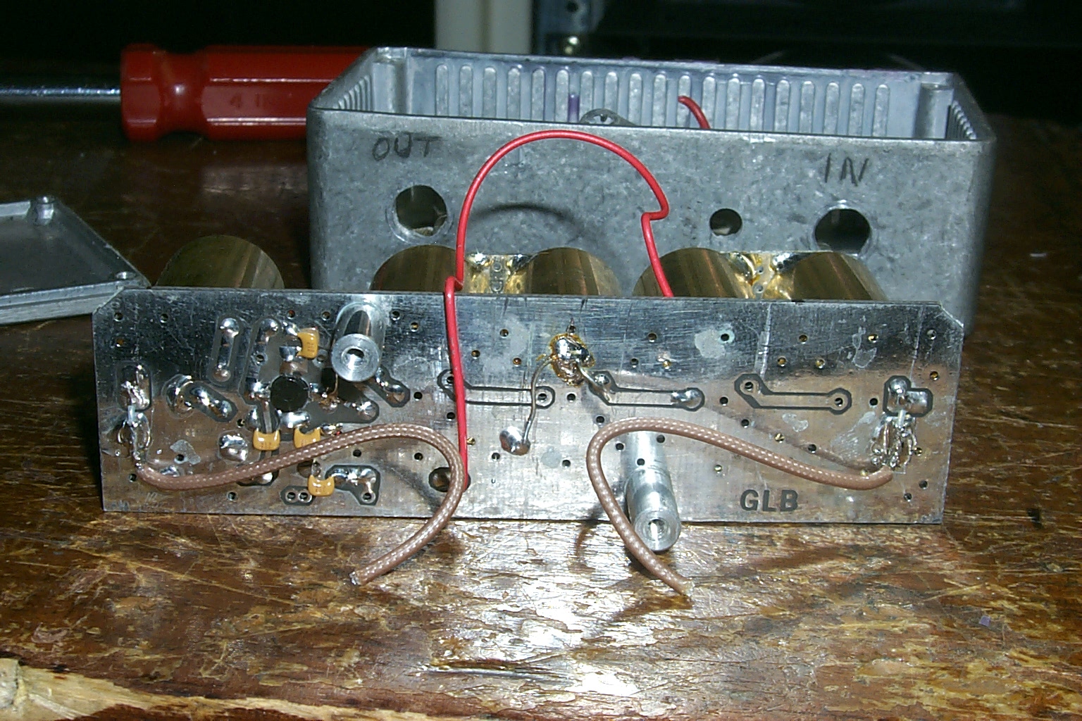
(click on images to enlarge)
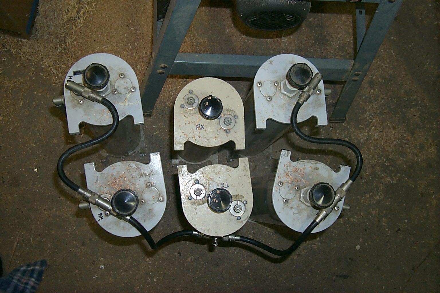
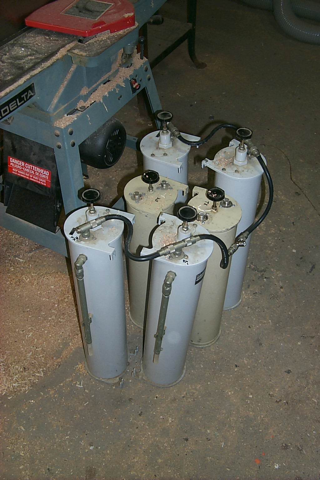
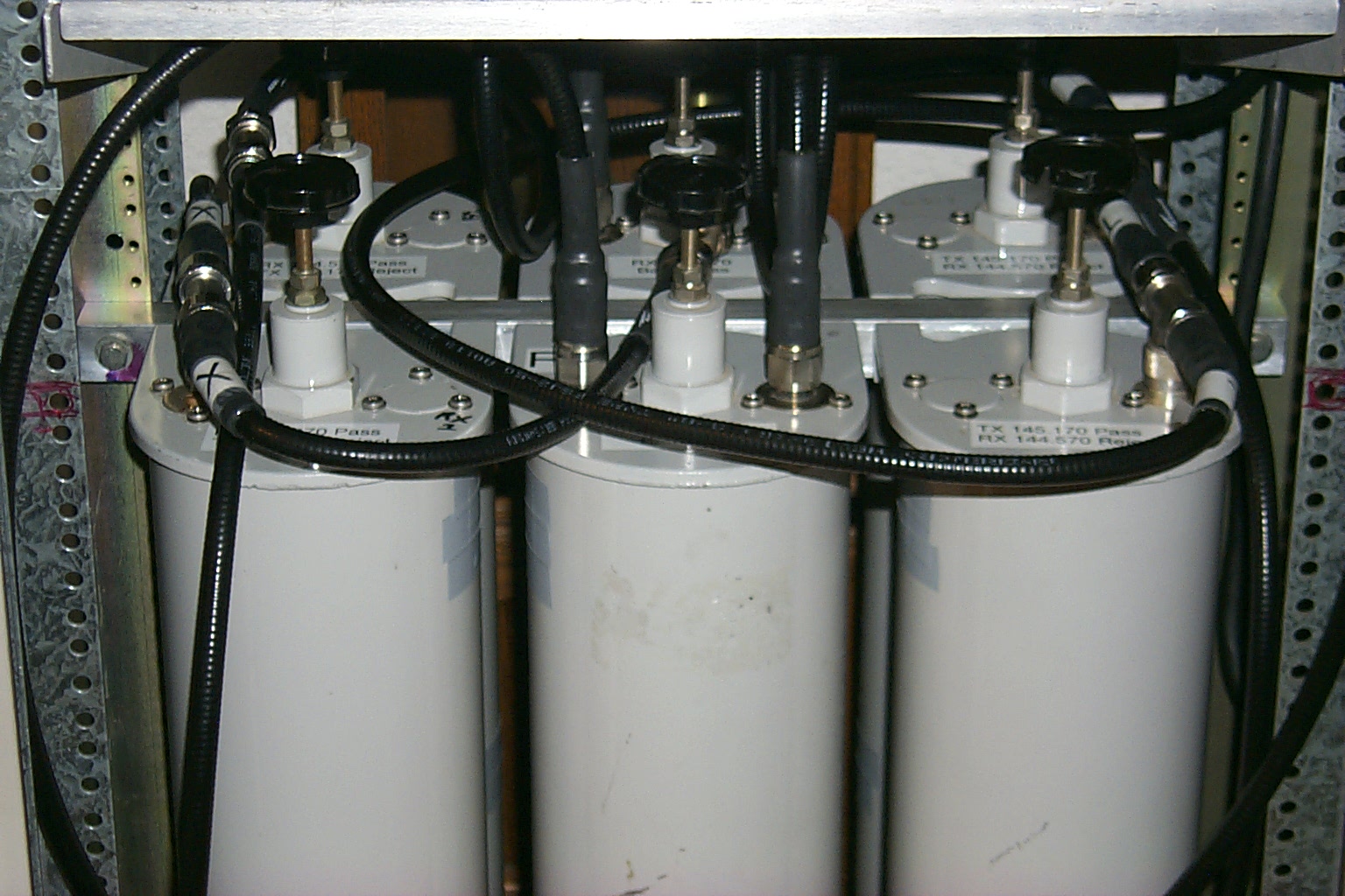
Update new duplexer cavities and mounting hardware
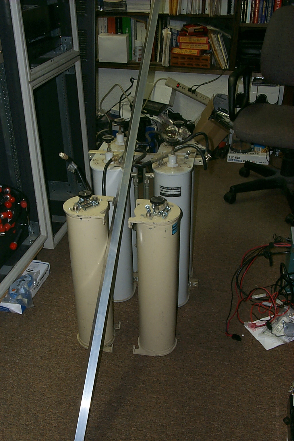
The VHF band pass cavities that I had added to Bill's four cavity BP/BR duplexer did not tune well down at 145 MHz and they were obviously built for much higher frequencies of 150 -174 MHz which were just not working out.
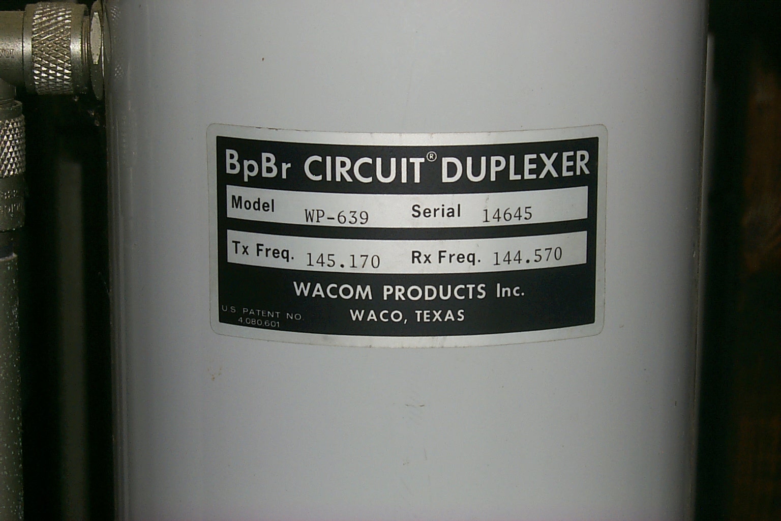
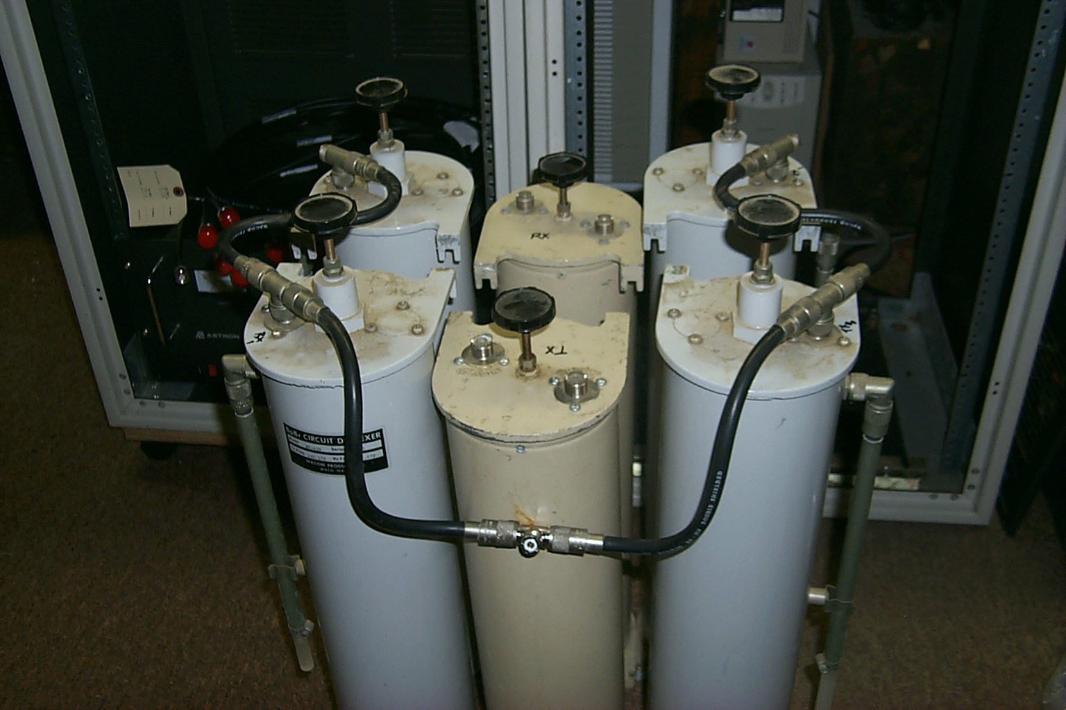
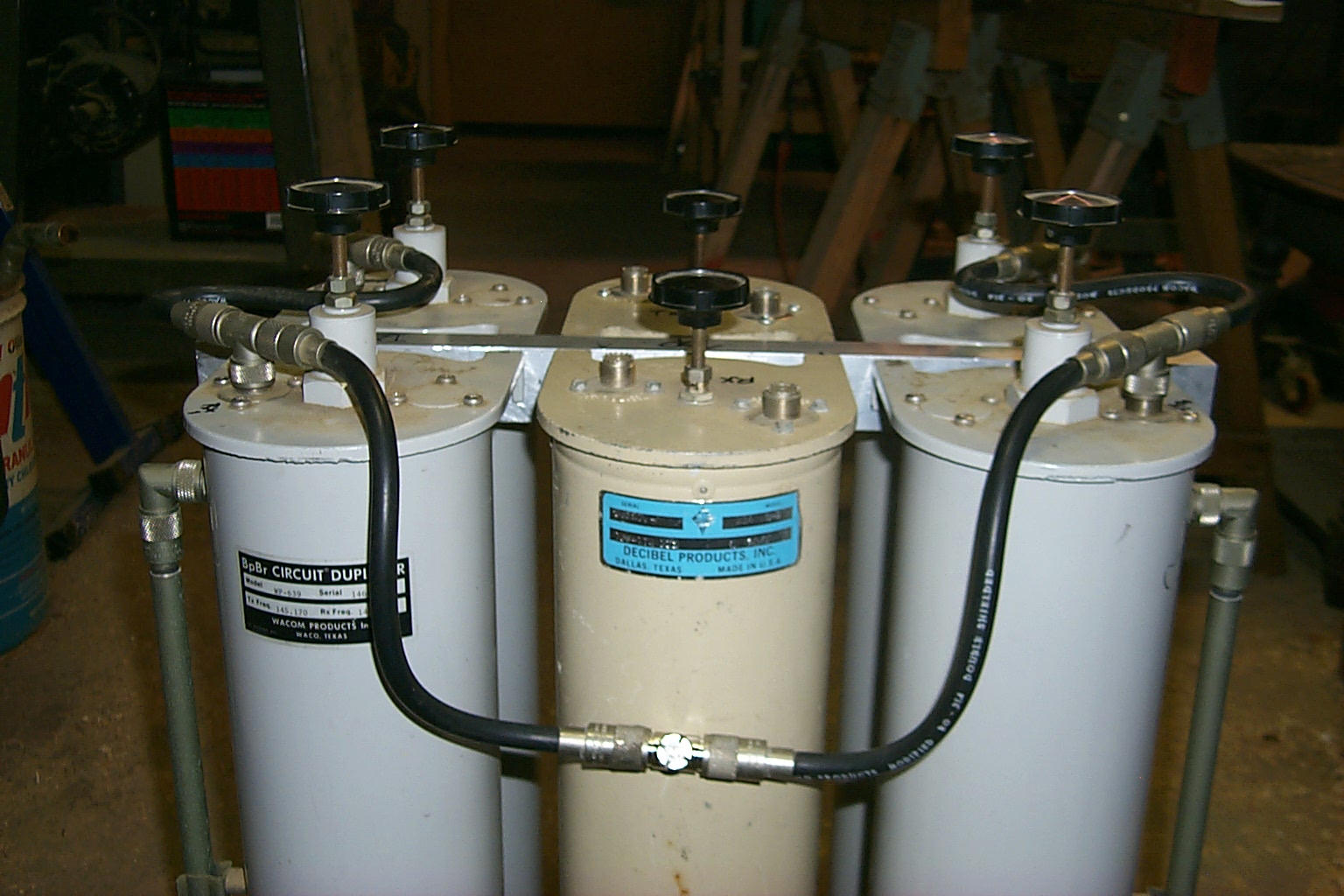
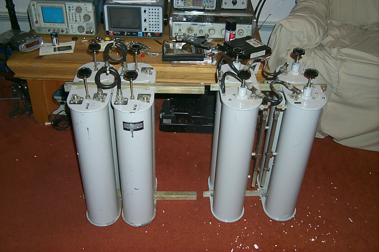
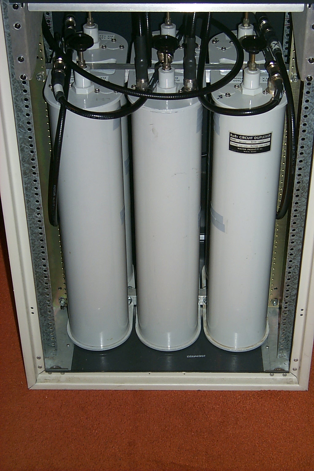
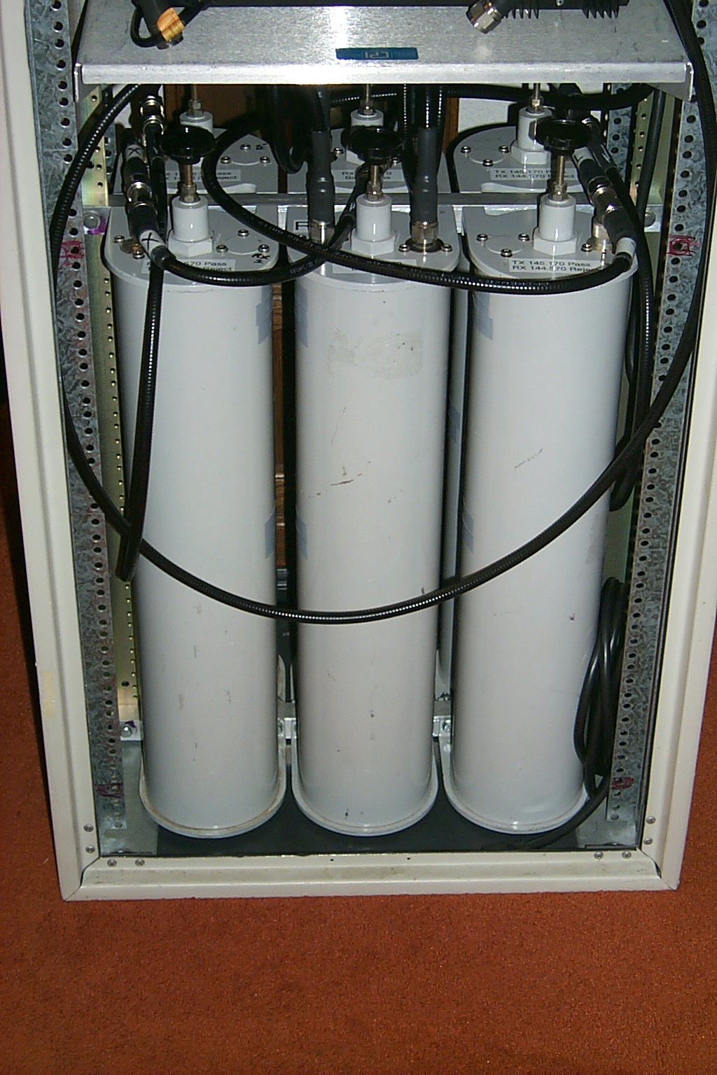
After an extensive search I was able to find several Wacom cavities made for the 144-148 MHz band split that were an exact match for Bill's original duplexer. I ended up purchasing four more BP/BR cavities like Bill's and four matching Band Pass cavities. This gave me enough matching VHF cavities to build TWO six cavity duplexers.
(Guess I will have to start looking for another VHF site!)
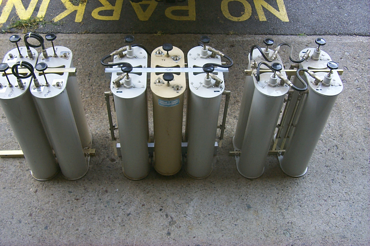
(click on images to enlarge)
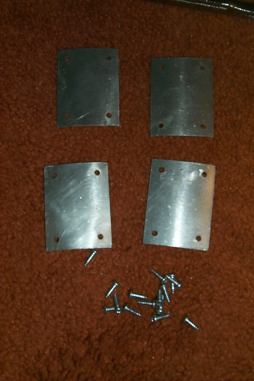
The mounting hardware described in the above story line and photos that Bruce KD1BE and I had fabricated in his shop were made to mount the two different size cavities. I could have re-used these brackets however decided to ask for help from Bruce and John to make another NEW set of mounting brackets for these new cavities. A few hours working with John Ash N1WEM in his shop we had a nice set of custom mounting brackets for this new configuration of duplexer cavities.
(click on images to enlarge) "Just drill
here" vs. "Lets think about this and measure"... I will make an assumption that we all know the difference
between Bruce's Just drill a hole here or the
"Hecker Method" and Jon's Lets think about
this and make a few measurements or the "Ash
Method" "Hecker Method" - During
my visit to Bruce's shop (first set of brackets)
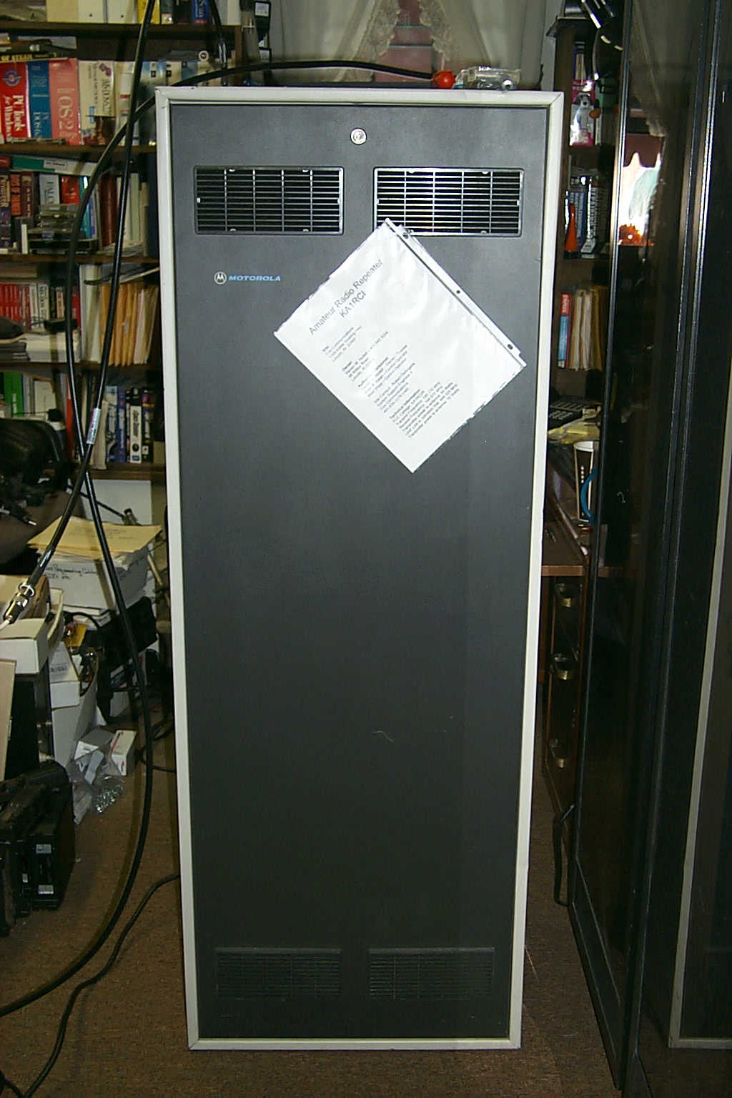
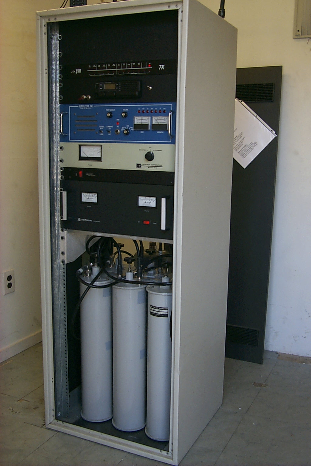
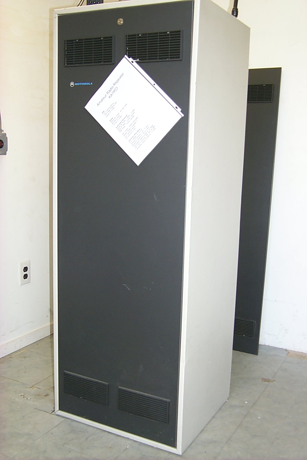
Update April 2009 New 60 inch Motorola Cabinet
After months of struggling with the two smaller 30 inch cabinets I was just not able to mount all the hardware for the repeater the way I wanted so I purchased a larger 60 inch cabinet and started rebuilding the repeater. I found this used 60 inch cabinet on eBay for $20.00 which is an insane price, the only problem was the seller located in California had it listed with (Local Pickup Only) and would not ship the cabinet. Luckily my friend Justin from work lives in near the seller and he was able to pick the cabinet for me and ship it to Rhode Island.
In these photos below I had just started mounting the new matching Wacom cavities in the new 60 inch rack cabinet. The next step will be to remove all the other hardware from the smaller 30 inch racks and rebuild everything into this new larger cabinet.
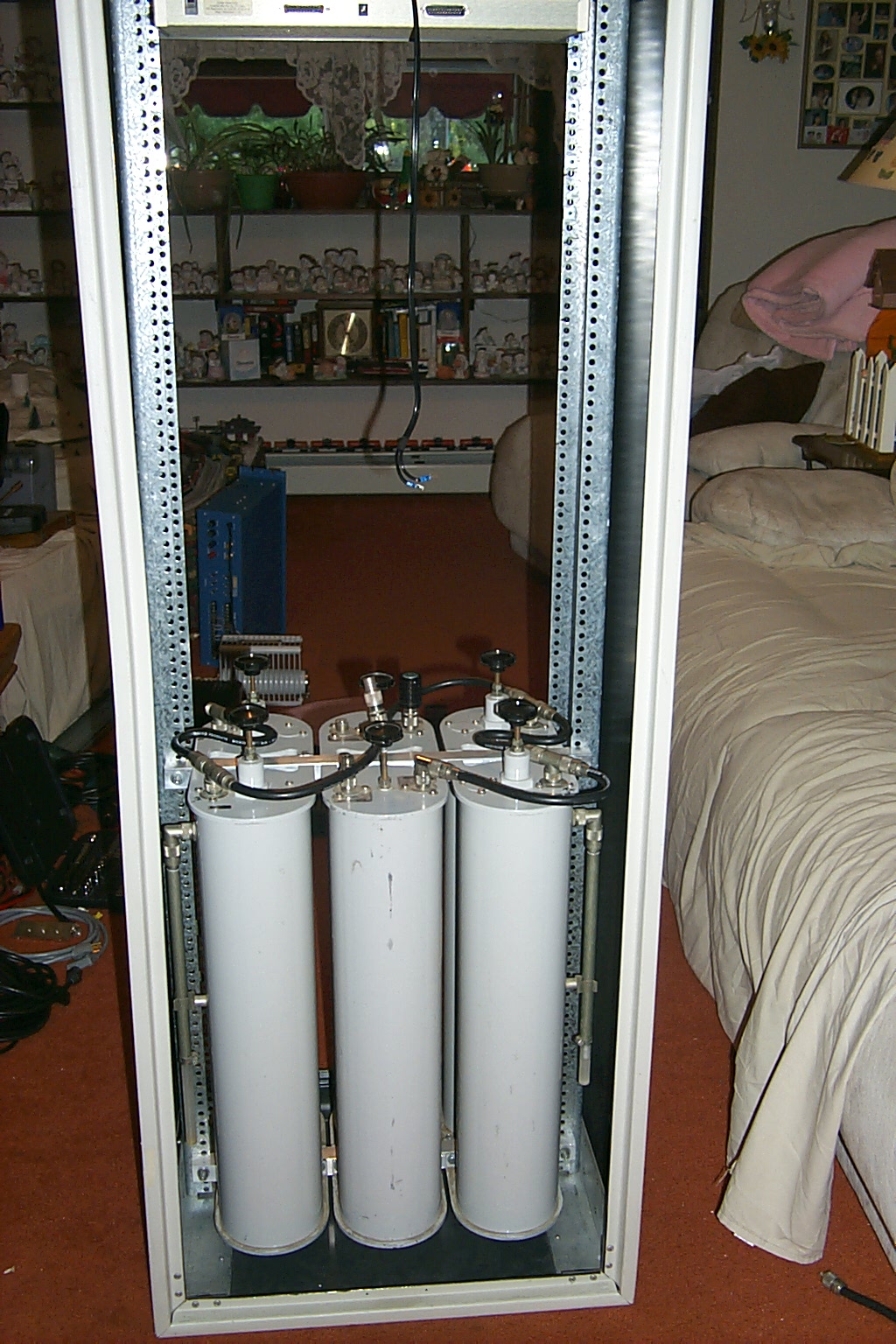
(click on images to enlarge)
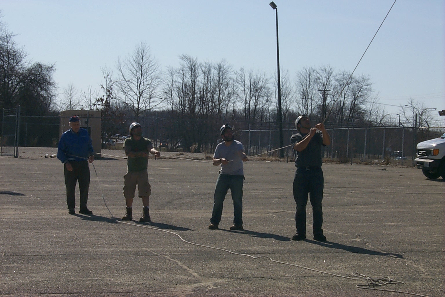
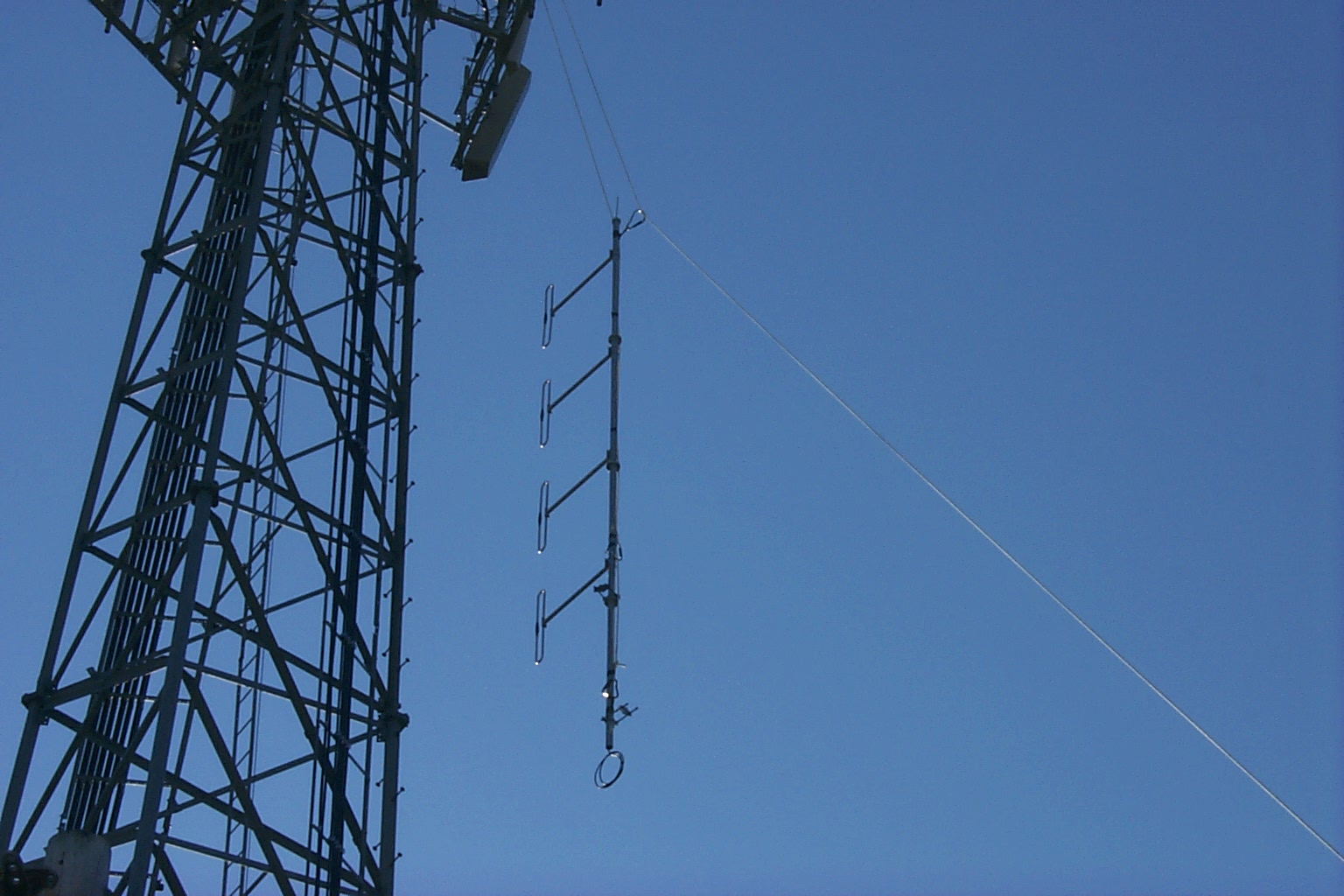
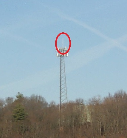
Update March 2010 - New Antenna!
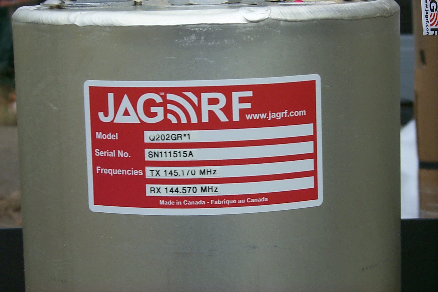
Finally the 17 year old Diamond X500-NHA antenna gets replaced with a new JAG Electromagnetics 150-4-1/2 half-wave 4-bay VHF dipole antenna.
These two photos show the new UHF Link antenna and Jag 50-4-1/2 half-wave 4-bay VHF dipole antenna.
(click on images to enlarge)
These photos show the tower crew preparing the new Jag antenna with mounting brackets.
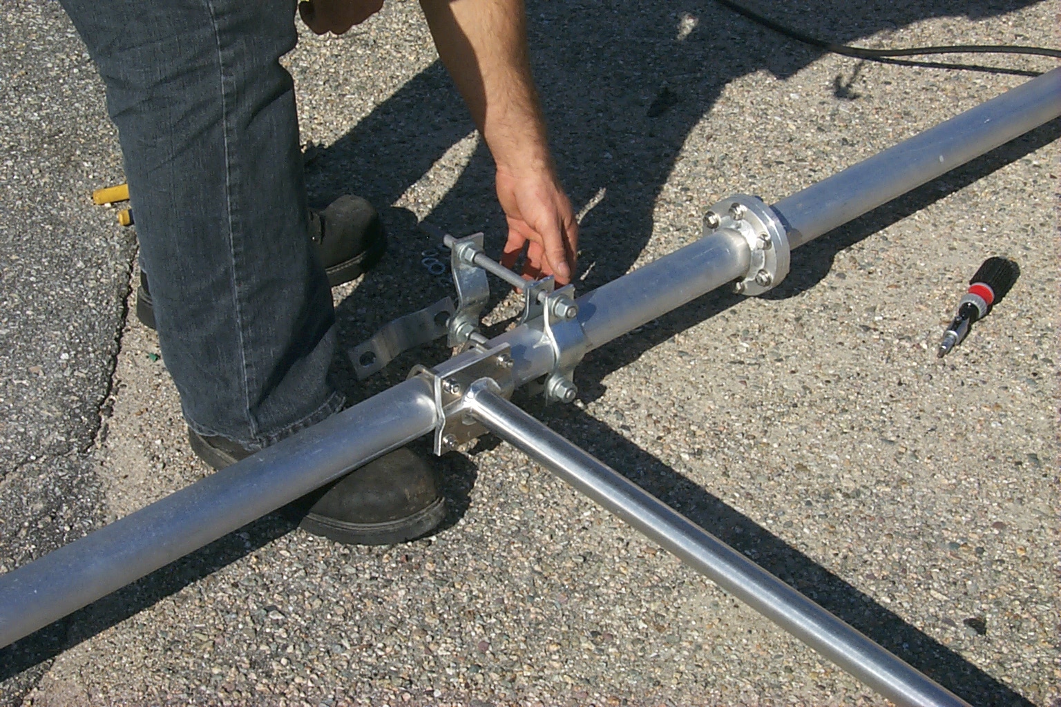
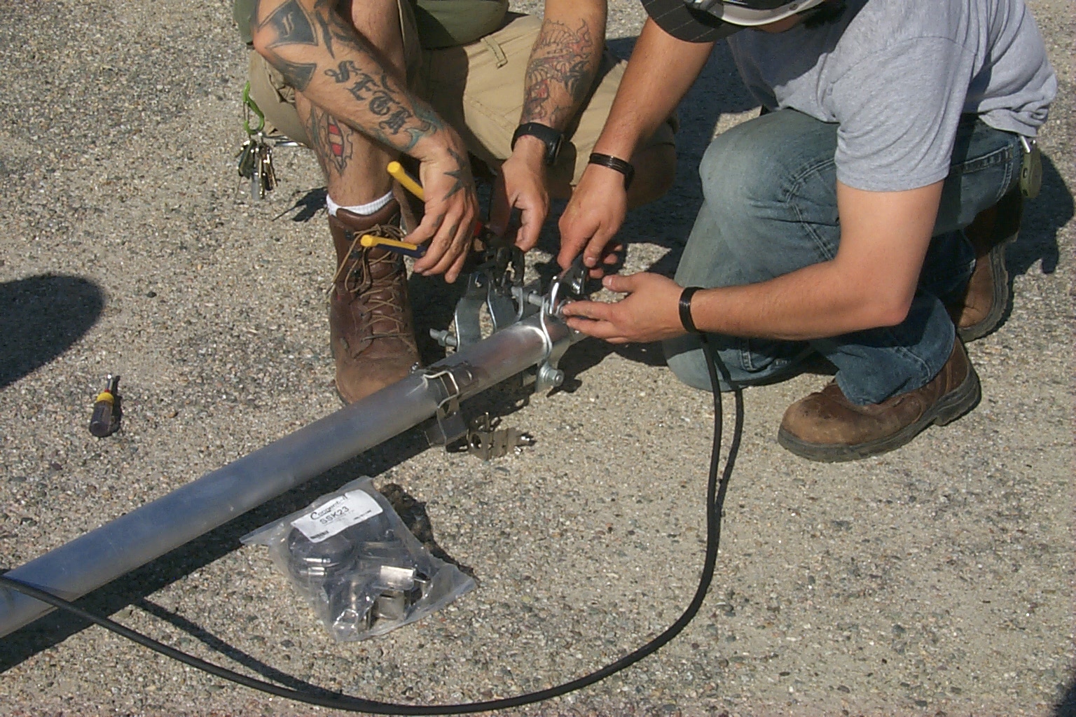
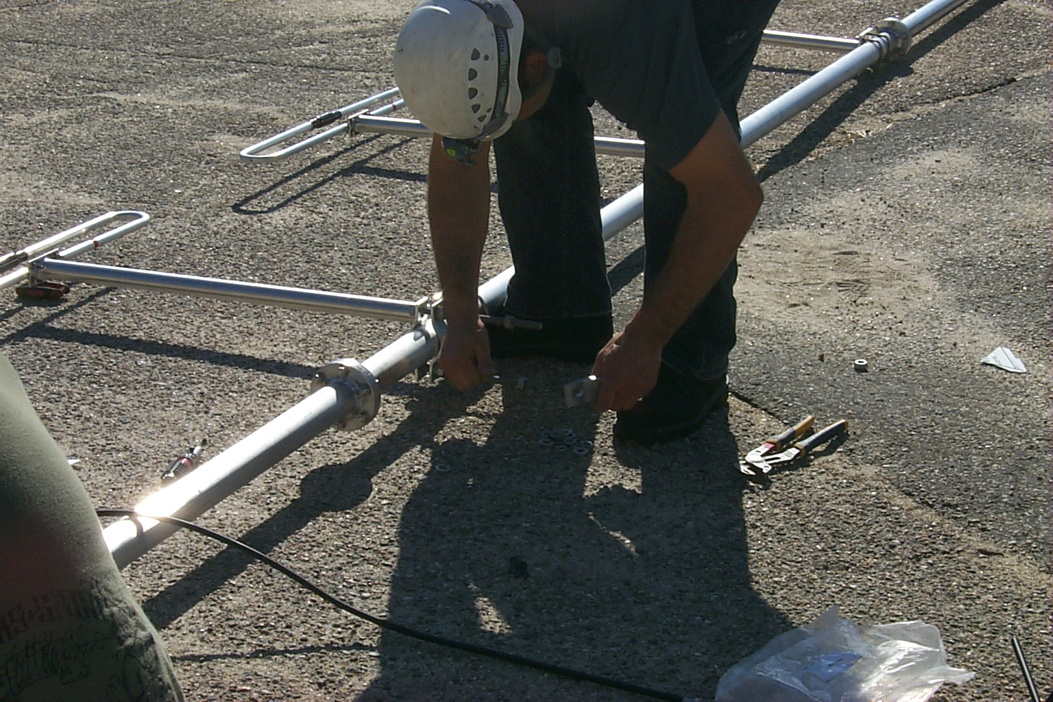
(click on images to enlarge)
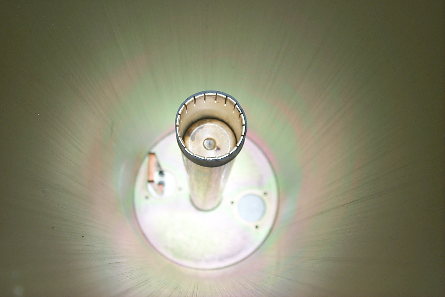
Installing one of the Andrew Female Type-N connectors on the LDF5 hard-line.
(click on images to enlarge)
Hoisting the new antenna to the top of the tower...
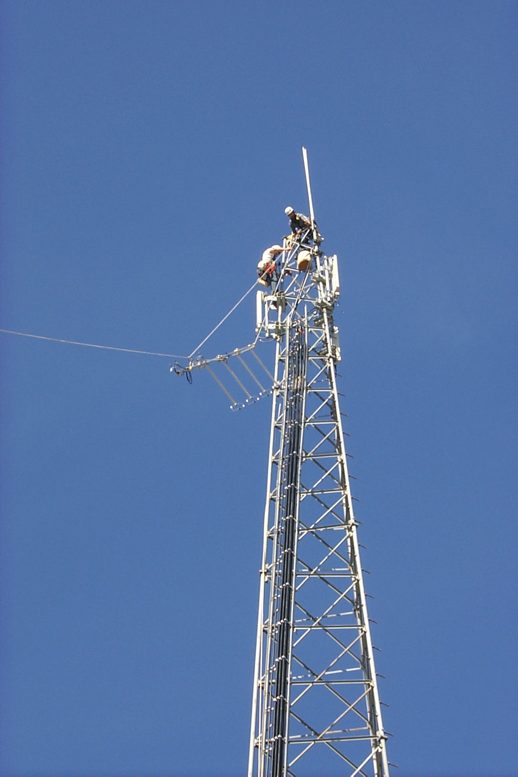
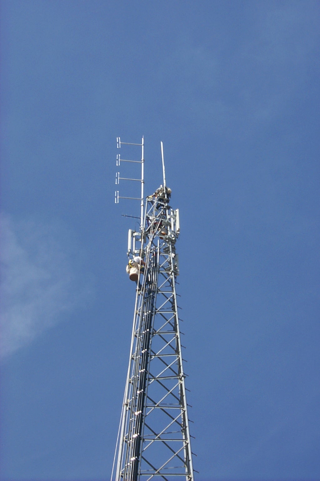
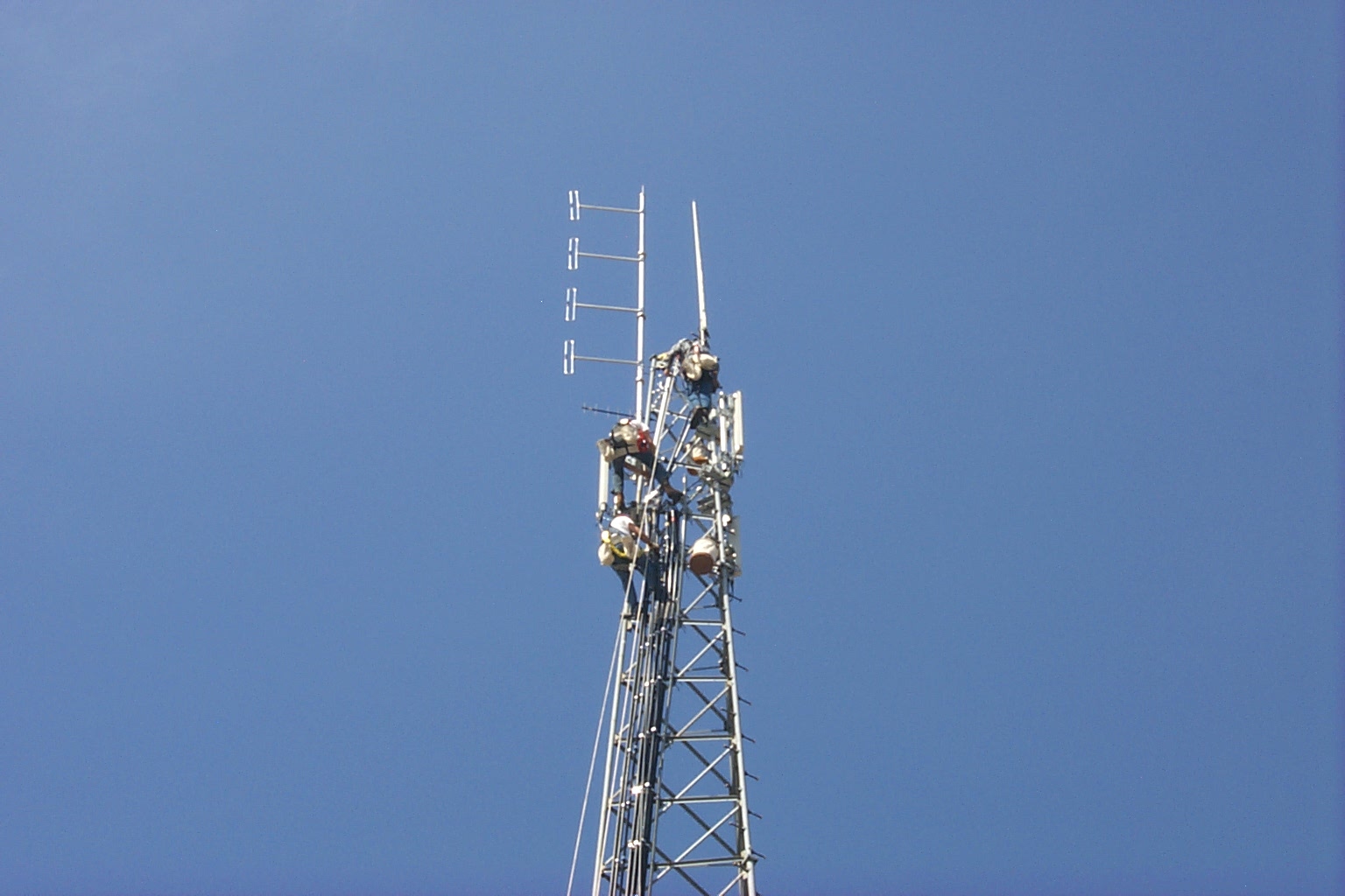
(click on images to enlarge)
Update April 2010 Another Duplexer Upgrade!
After such great success rebuilding the Wacom cavities for the Exeter 146.985 repeater with new custom JAG Electromagnetics Type-N coupling loops I decided to rip apart the 145.170 Wacom cavities and upgrade them as well.
In these photos you can see the new custom JAG loops being fabricated in the JAG Electromagnetics lab.
(click on images to enlarge)
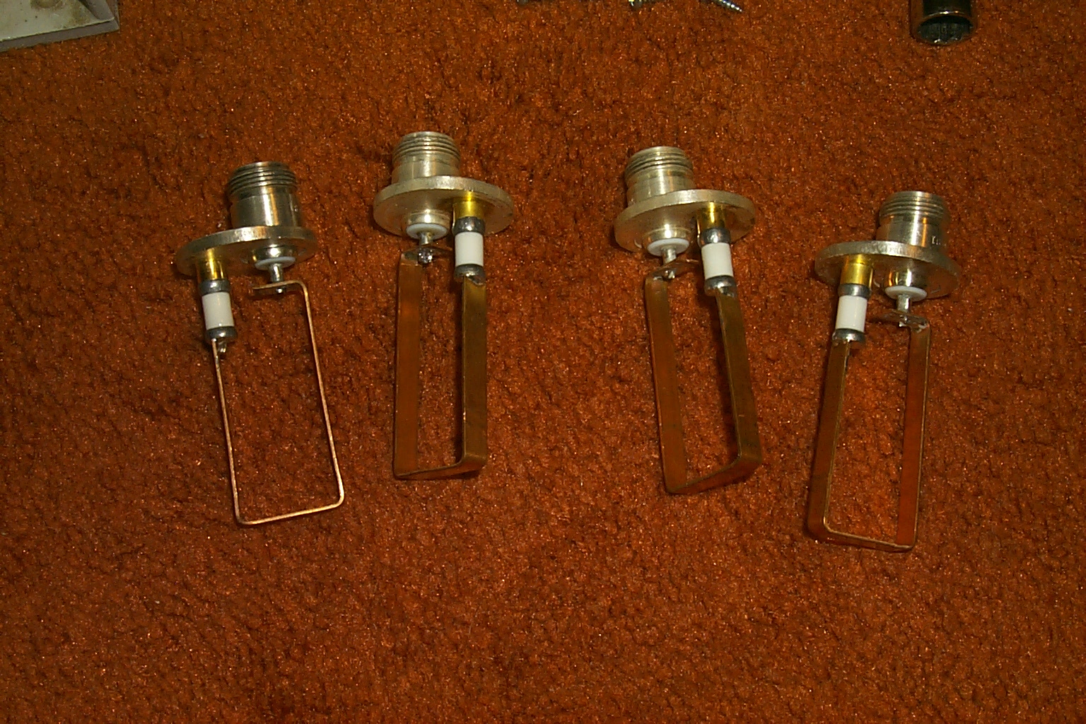
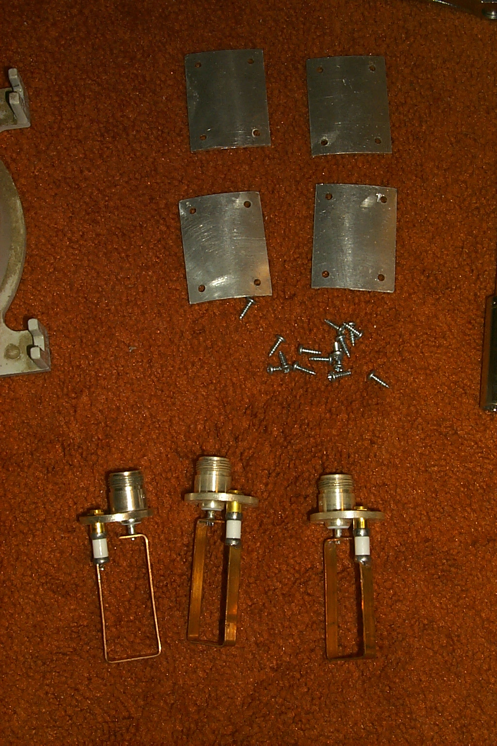
These photos show the new custom Type-N JAG band-pass / band-reject loops and original Type-N Wacom band-pass loops that I will use to rebuild the six Wacom cavities for the 145.170 Lincoln repeater.
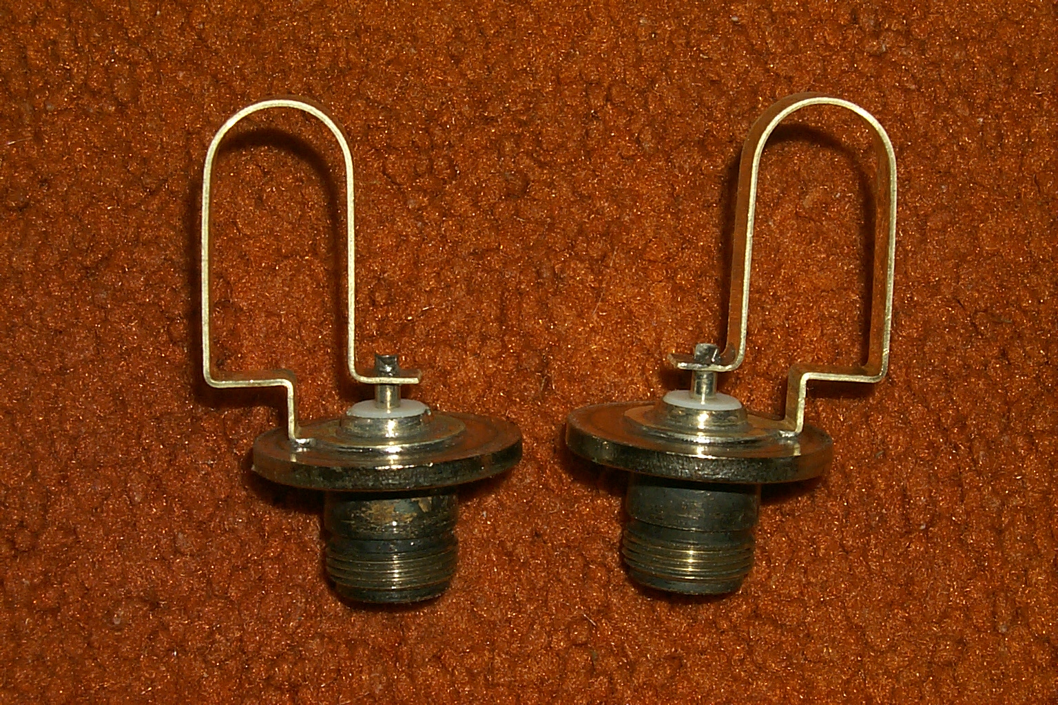

(click on images to enlarge)
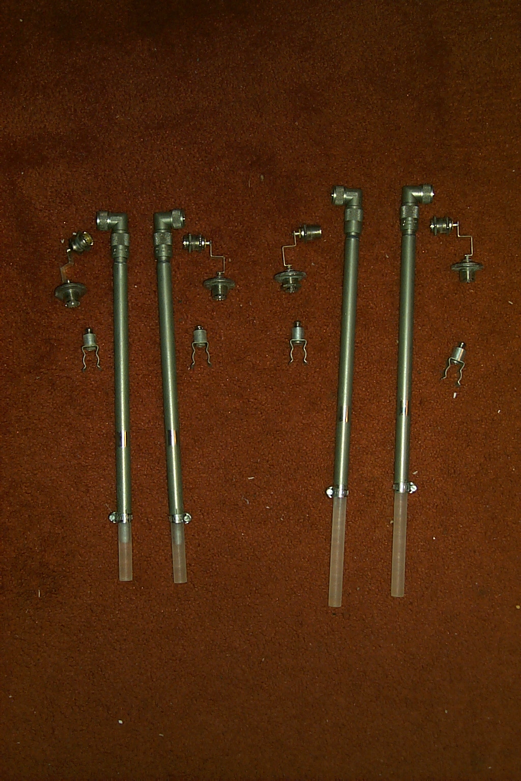
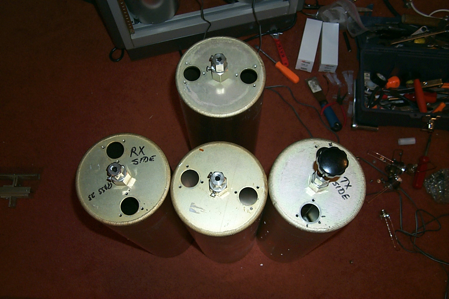
The first step was to take all of the original SO-239 hardware out of the cavities and clean everything.
(click on images to enlarge)
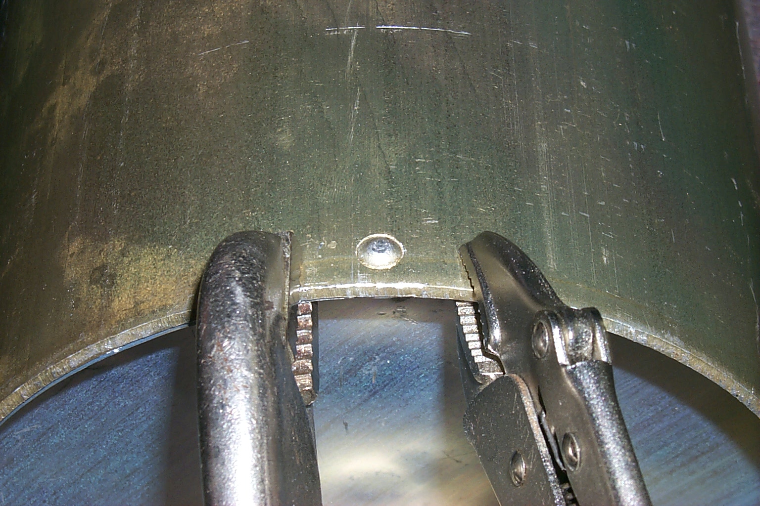
In these photos I have removed all of the old coupling loops and eternal reject notch tuning rods.
(click on images to enlarge)
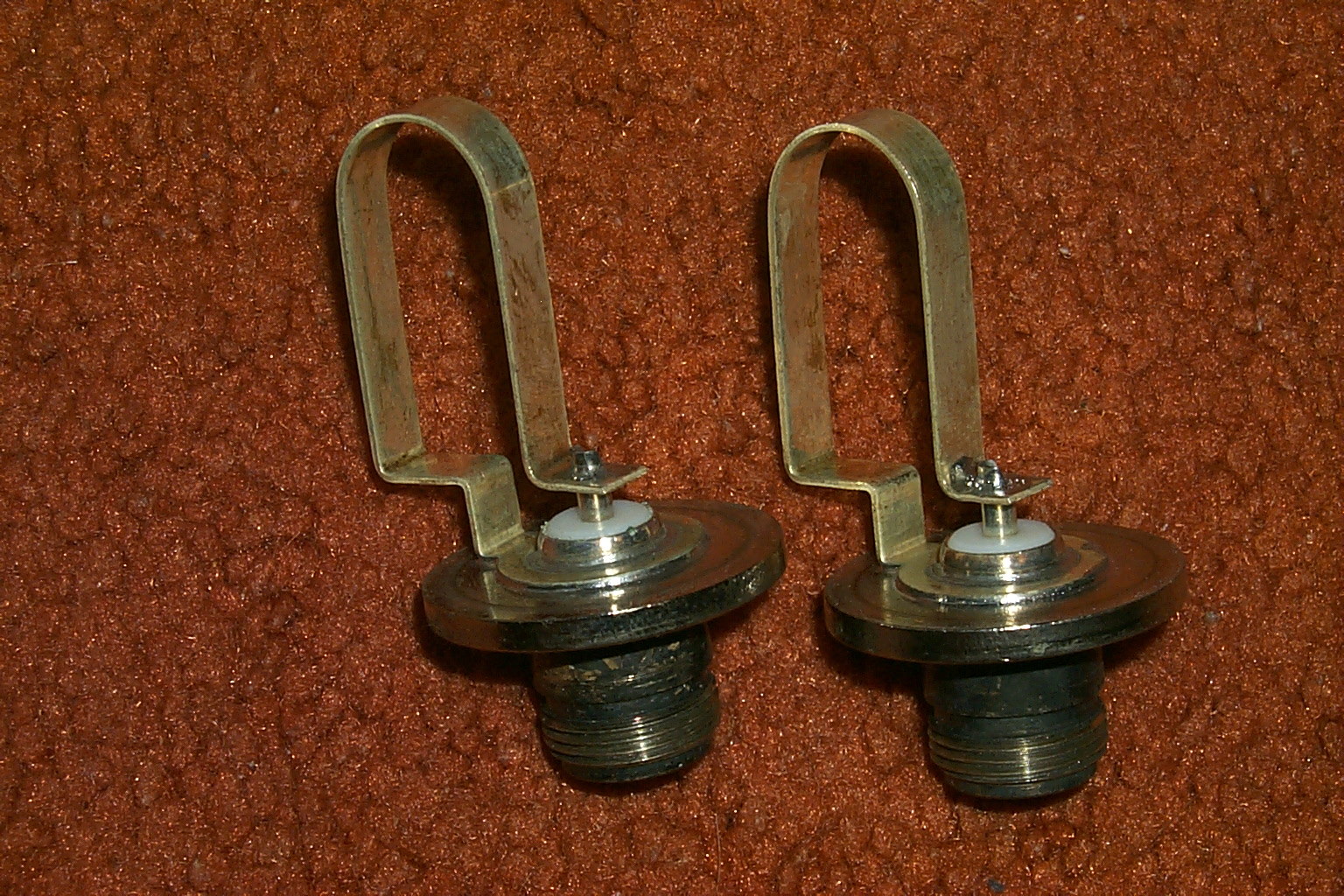
Here are some photos of the new custom Jag Type-N coupling loops with the piston caps for reject notch tuning and the plates to cover the holes where the external reject tuning rods had been mounted.
(click on images to enlarge)
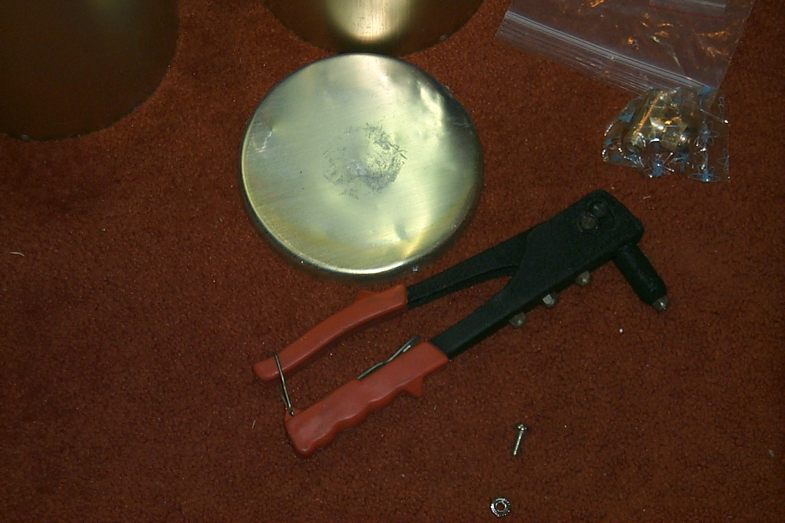
The first cavity gets upgraded... I cleaned out the hole in the top of the cavity, installed the new custom Jag Type-N coupling loop, installed the cover plate, and put a self tapping machine screw in the hole mid way down the side of the cavity where the clip for the reject tuning rod had been mounted.
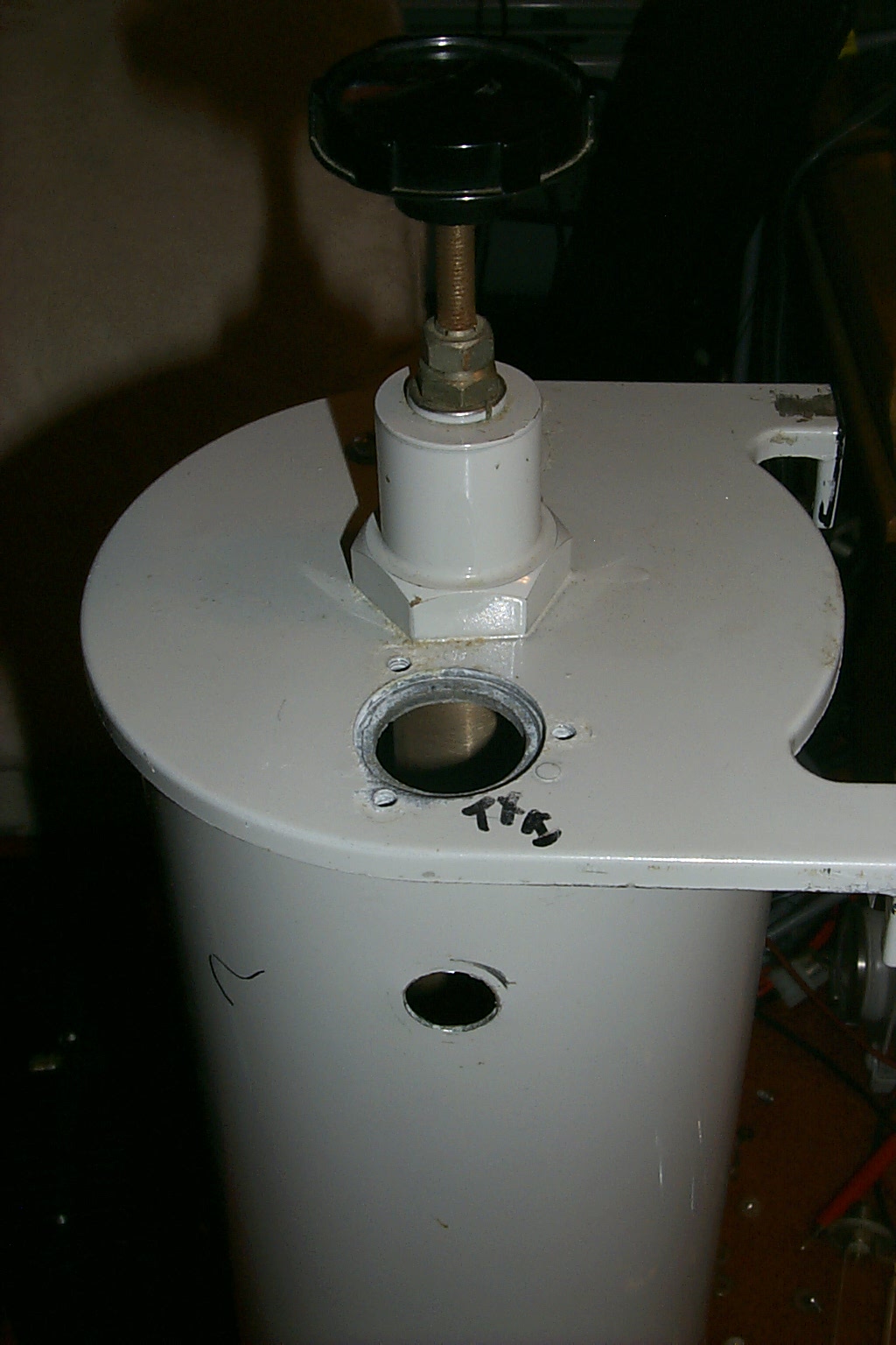
(click on images to enlarge)
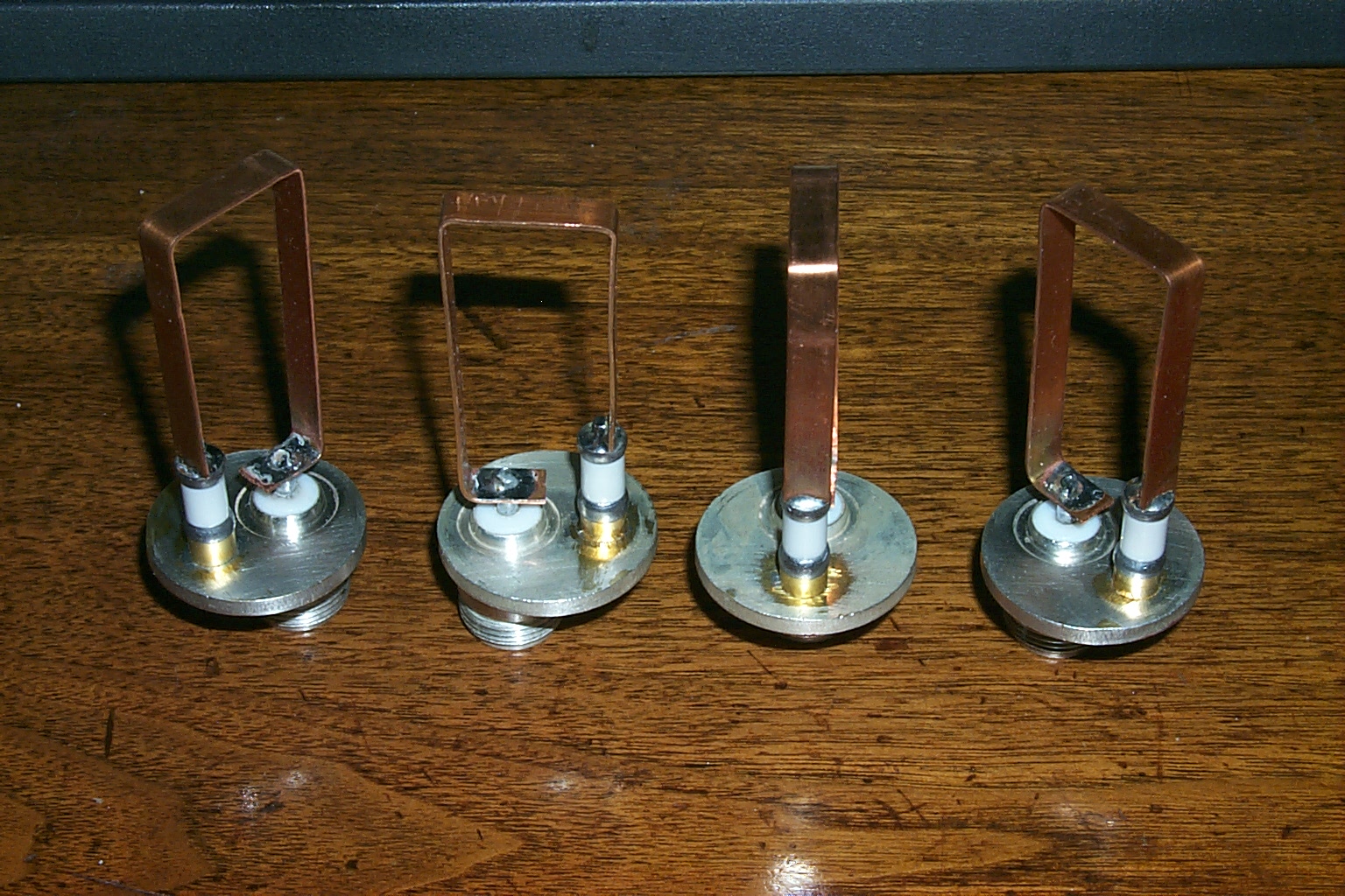
One finished, five more to go... Should be easy right?
Wrong!
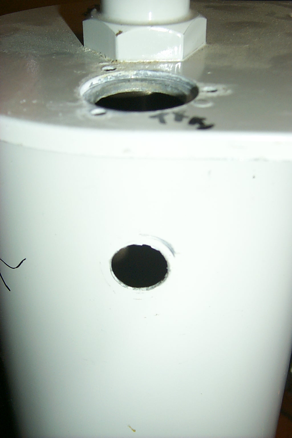
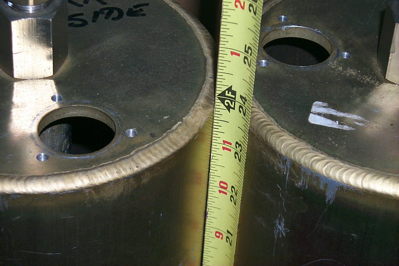
More than twenty years of moisture had cause a large amount of aluminum oxide to build up around the openings for the coupling loops and inside the cavities, they were a mess. As I started working on all the other cavities each one seemed worse than the one before. By the time I made it to the last cavity I had lost all my patience and ended up damaging the recessed mounting hole for the coupling loop.
(click on images to enlarge)
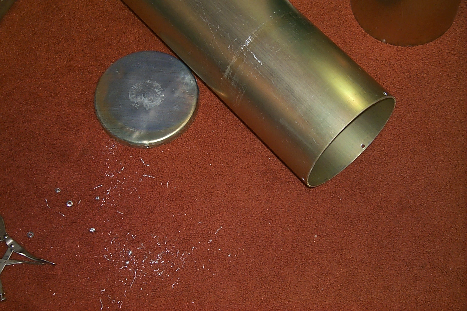
Then instead of stepping back and taking a break I started taking everything apart while I was angry and ended up causing more damage.
(click on images to enlarge)
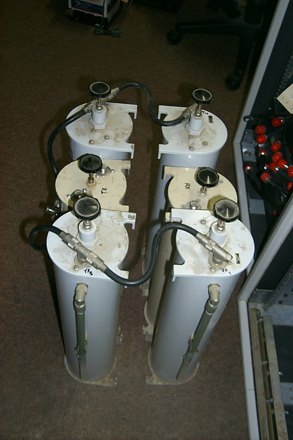
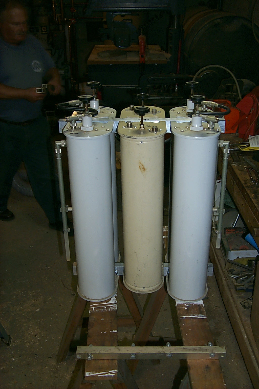
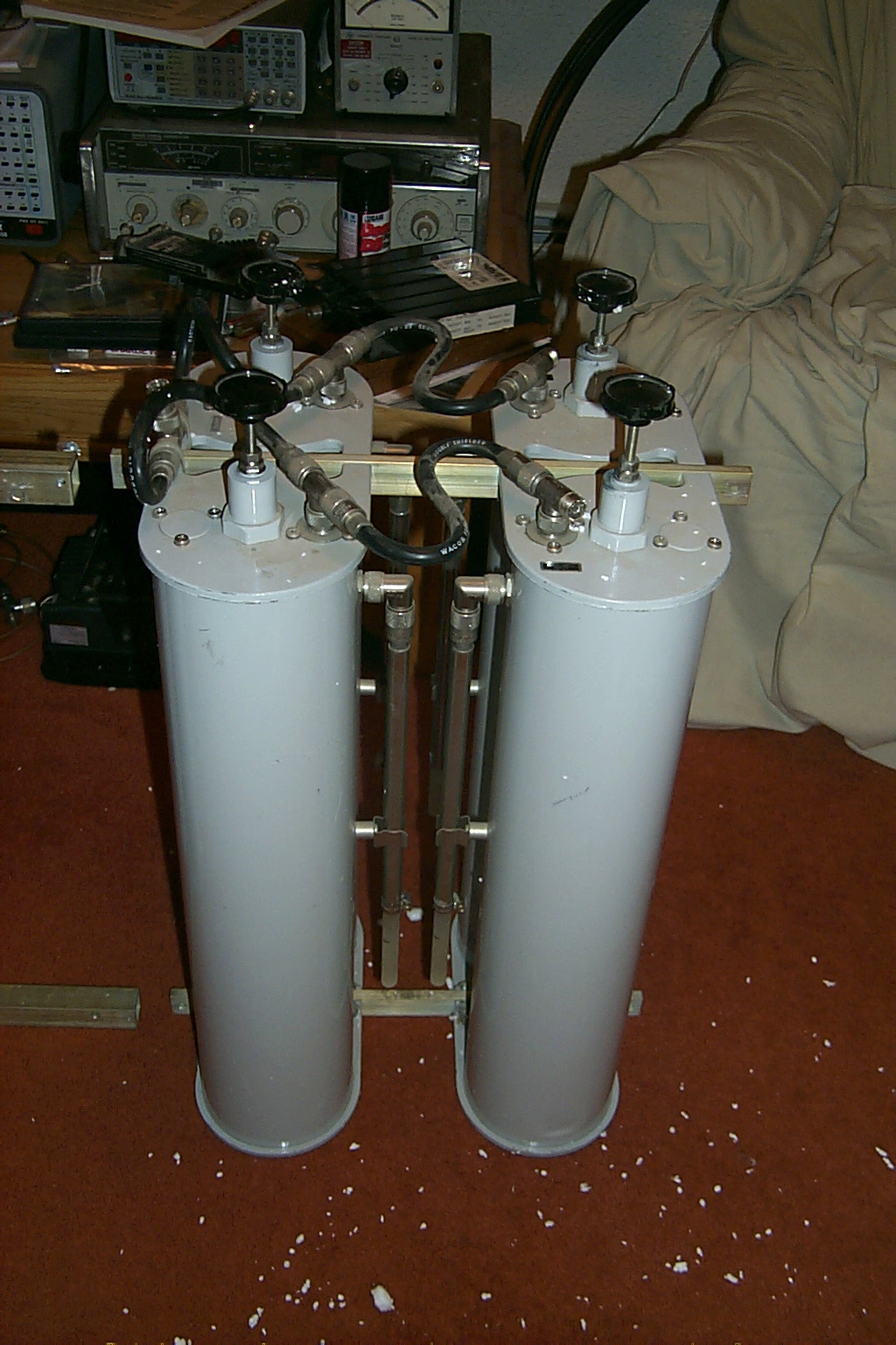
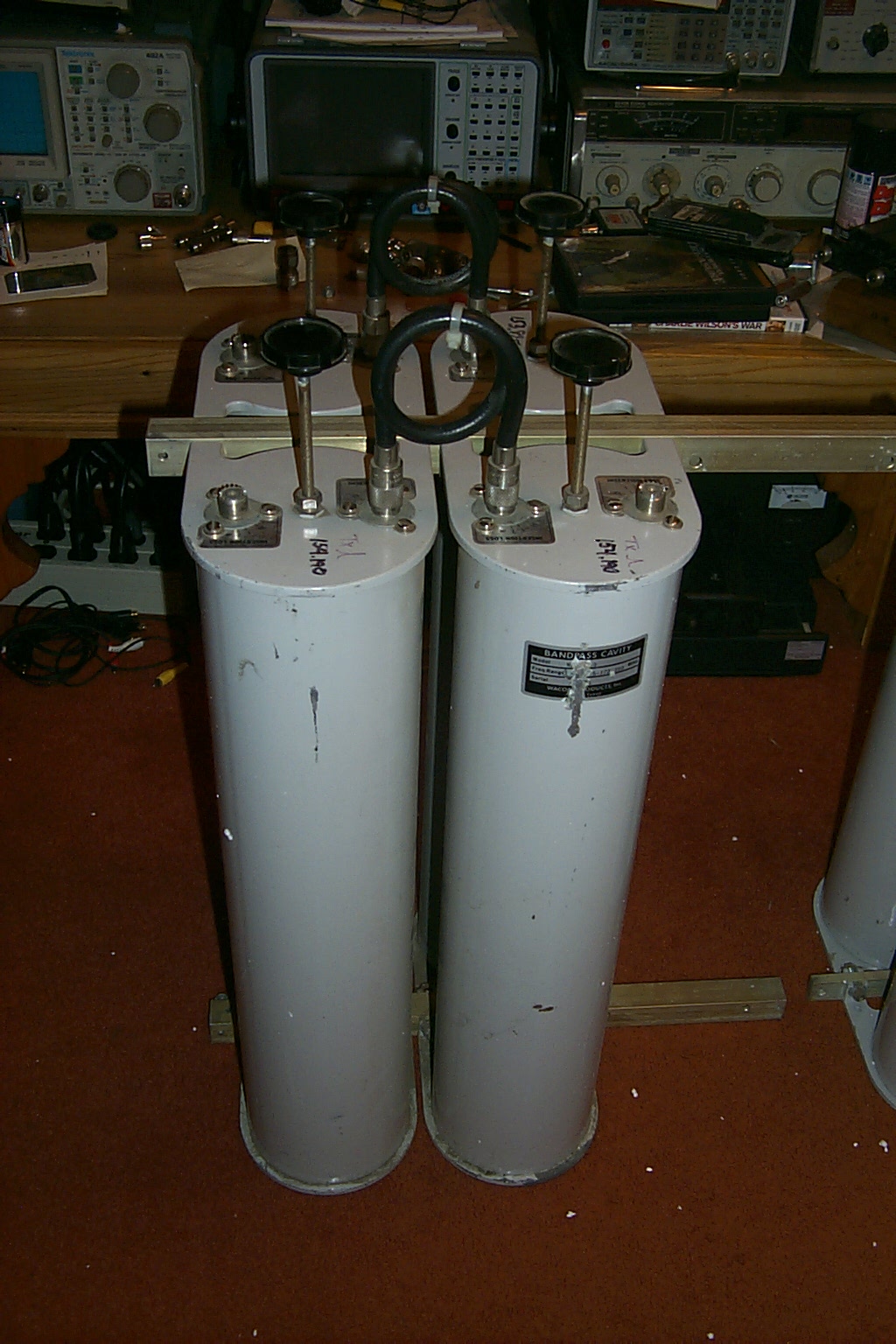
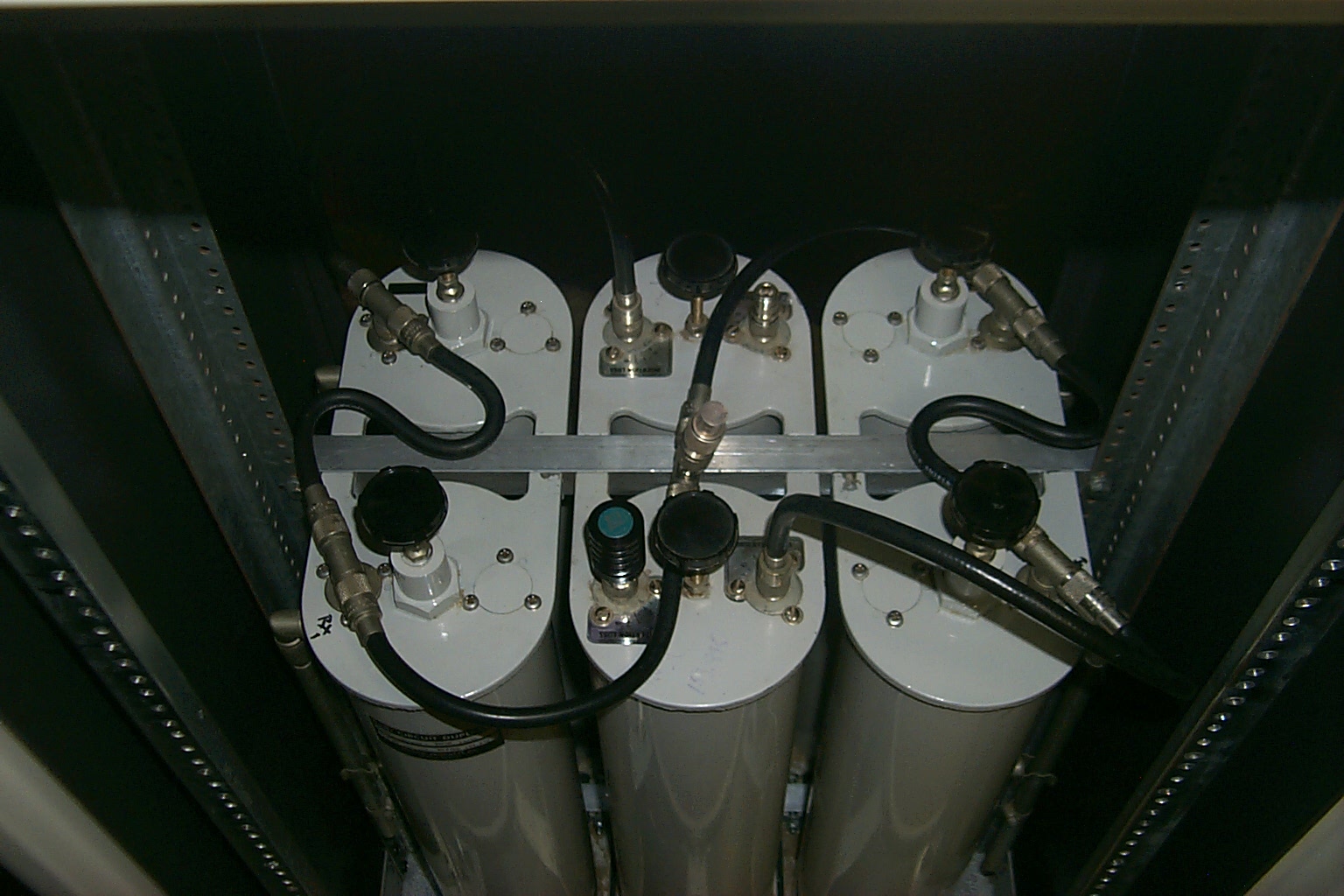
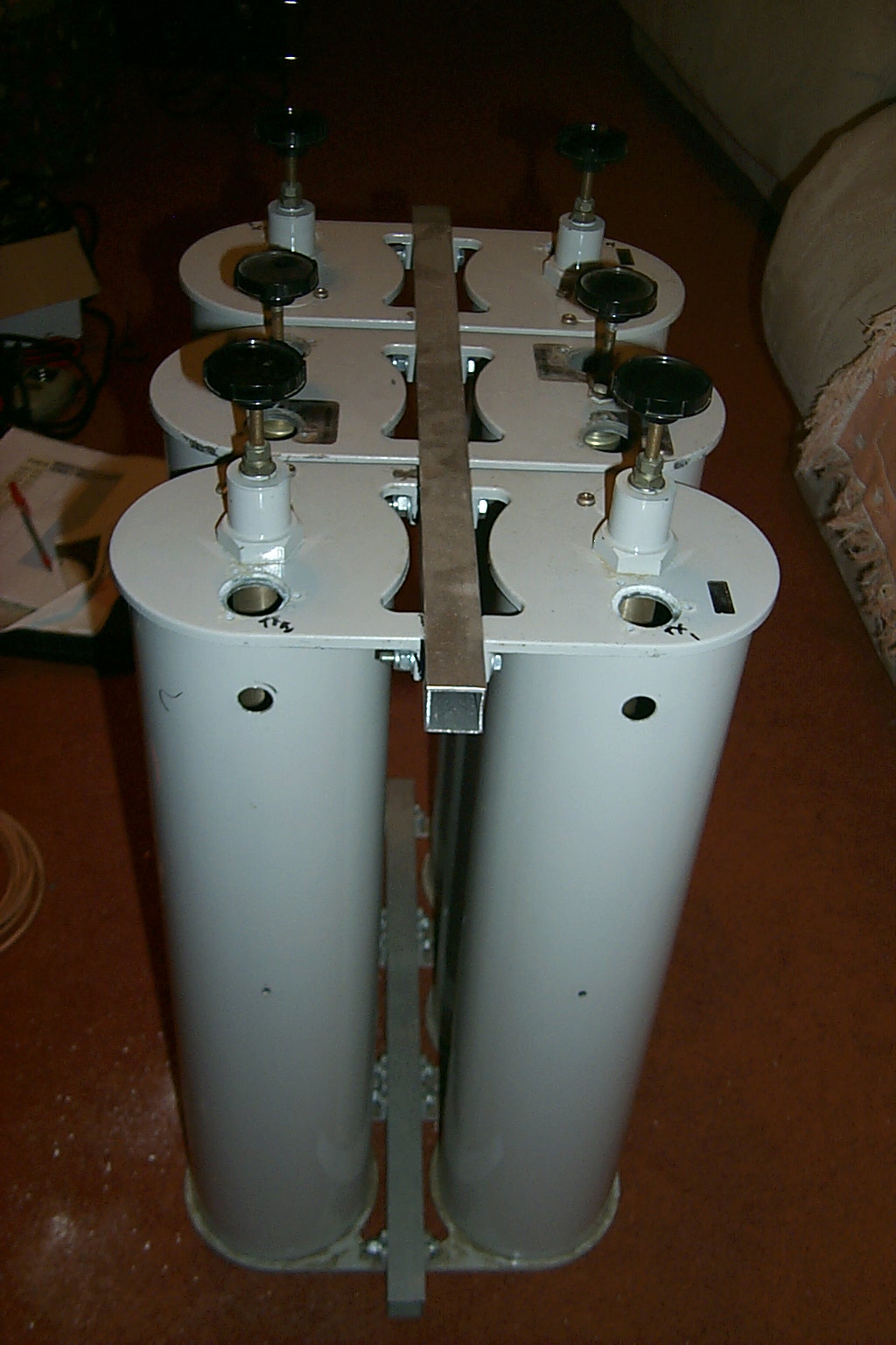
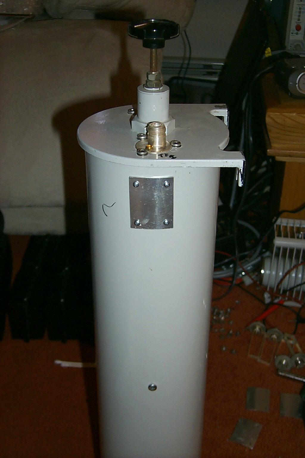
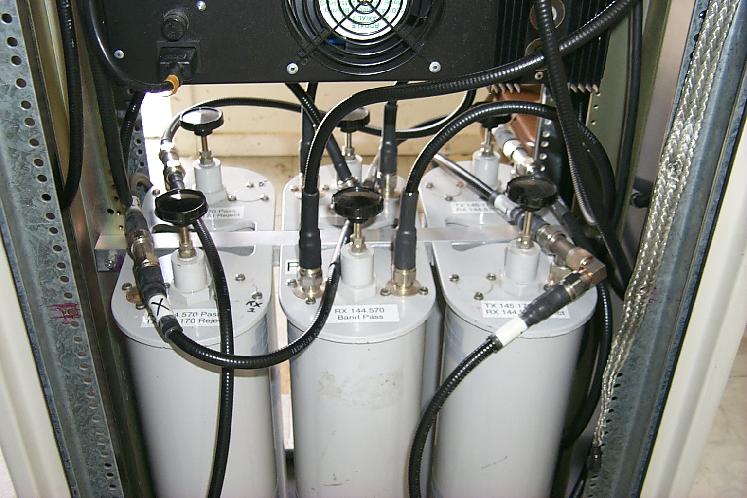
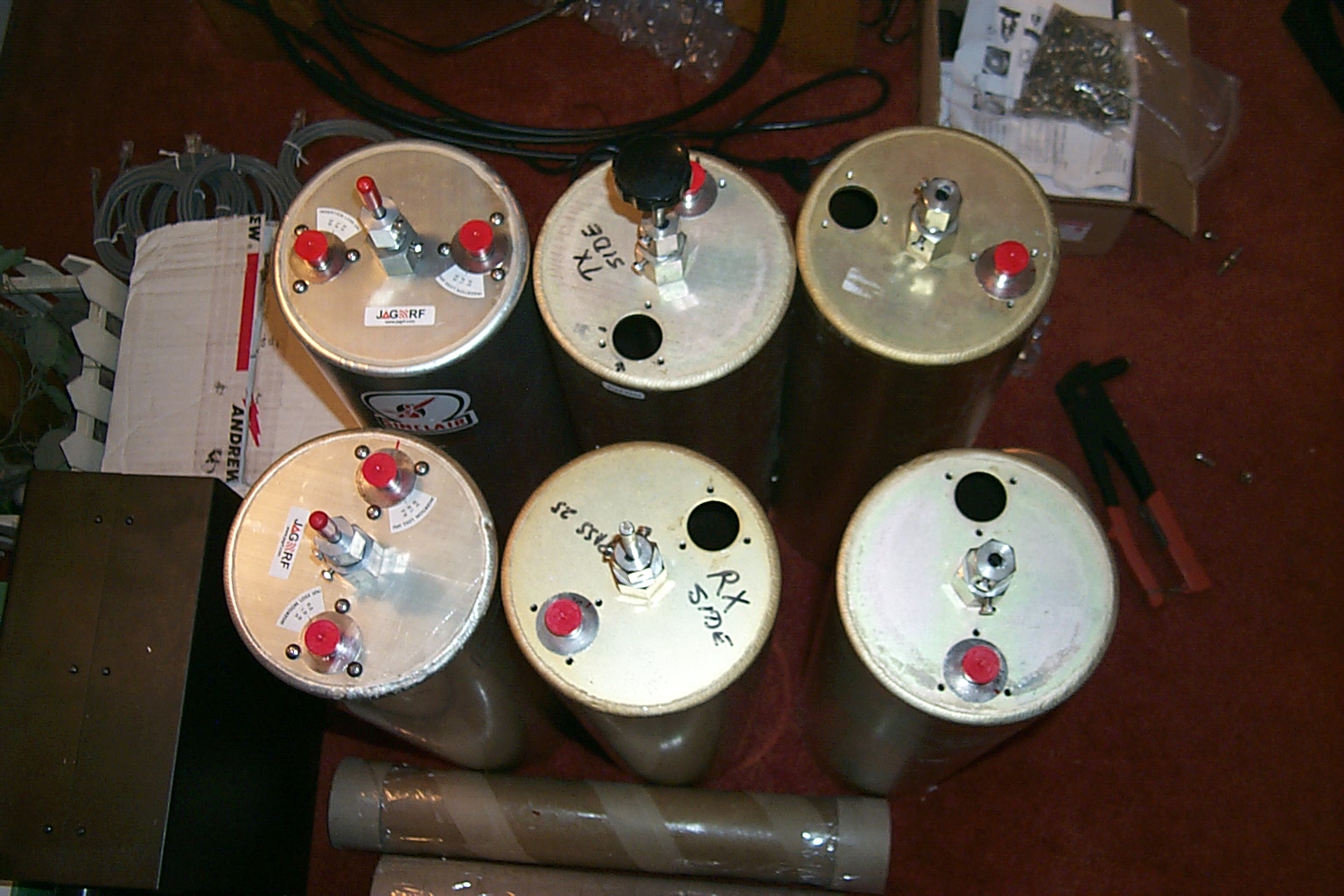
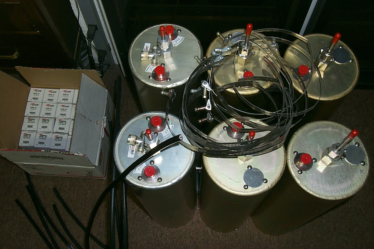
In the long run, this turned out to be a good thing as I ended up using the spare set of Wacom cavities that I had been saving for another project. These were an exact match to Bill's original cavities and much higher quality so the finished six cavity duplexer turned out even better than I had expected.
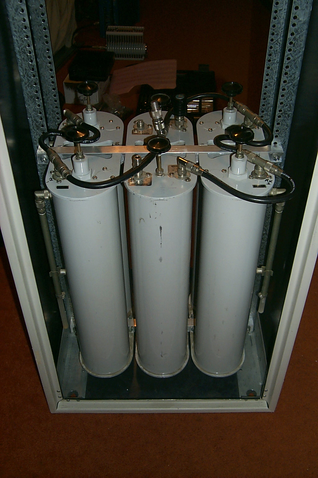
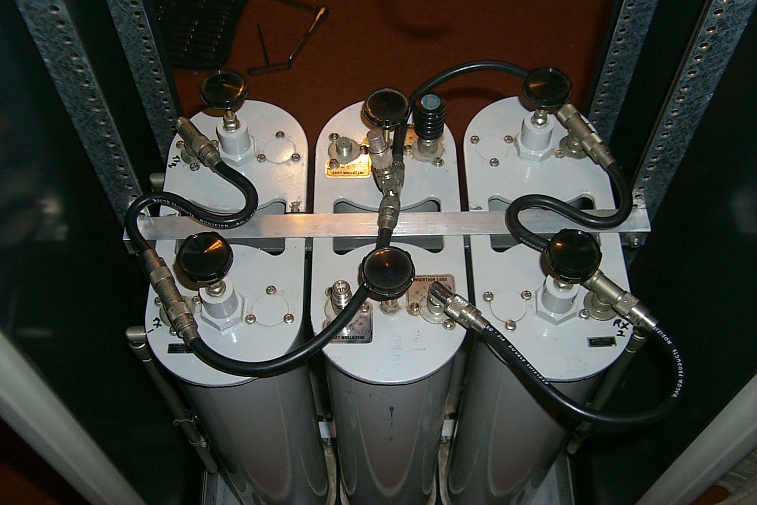
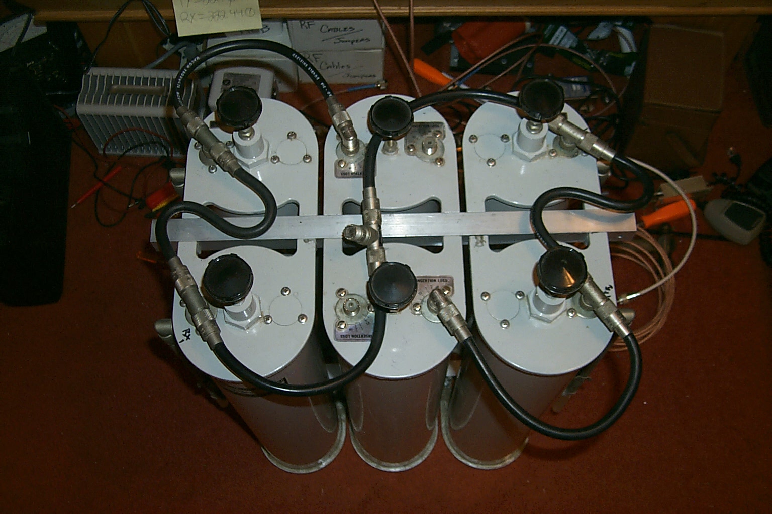
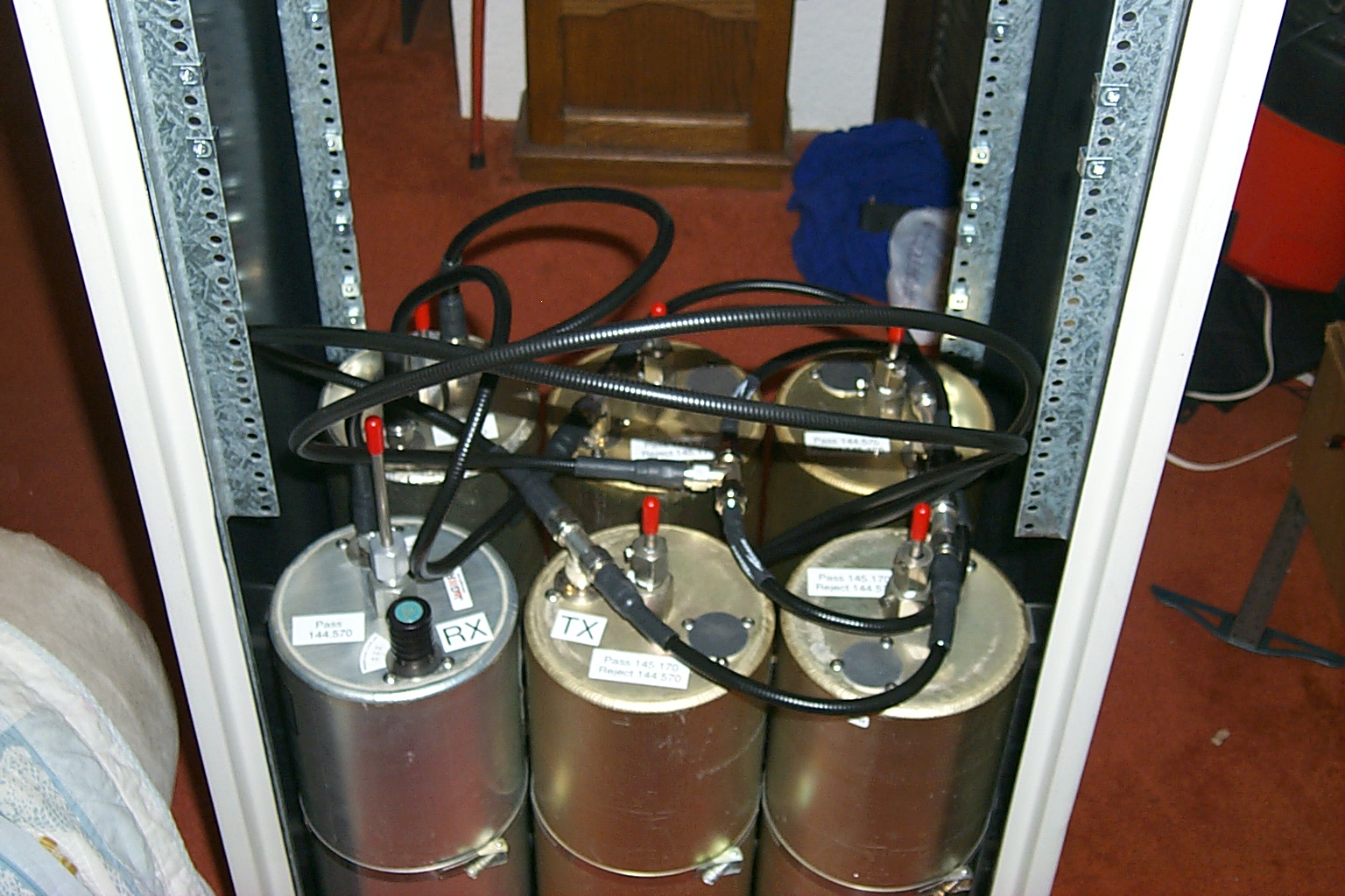
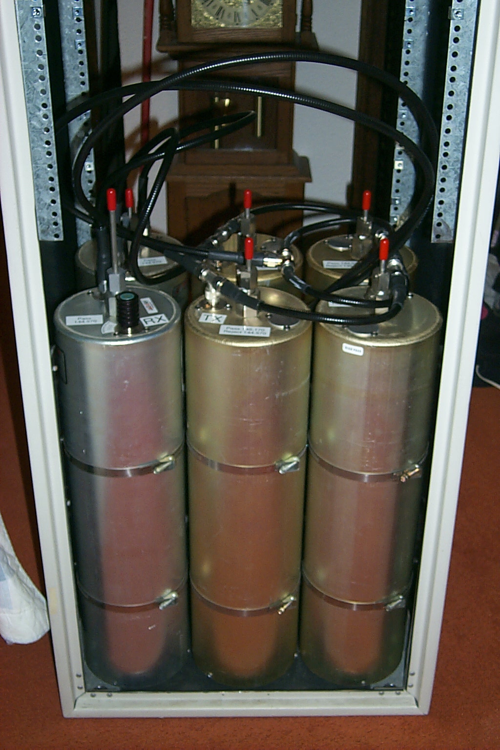
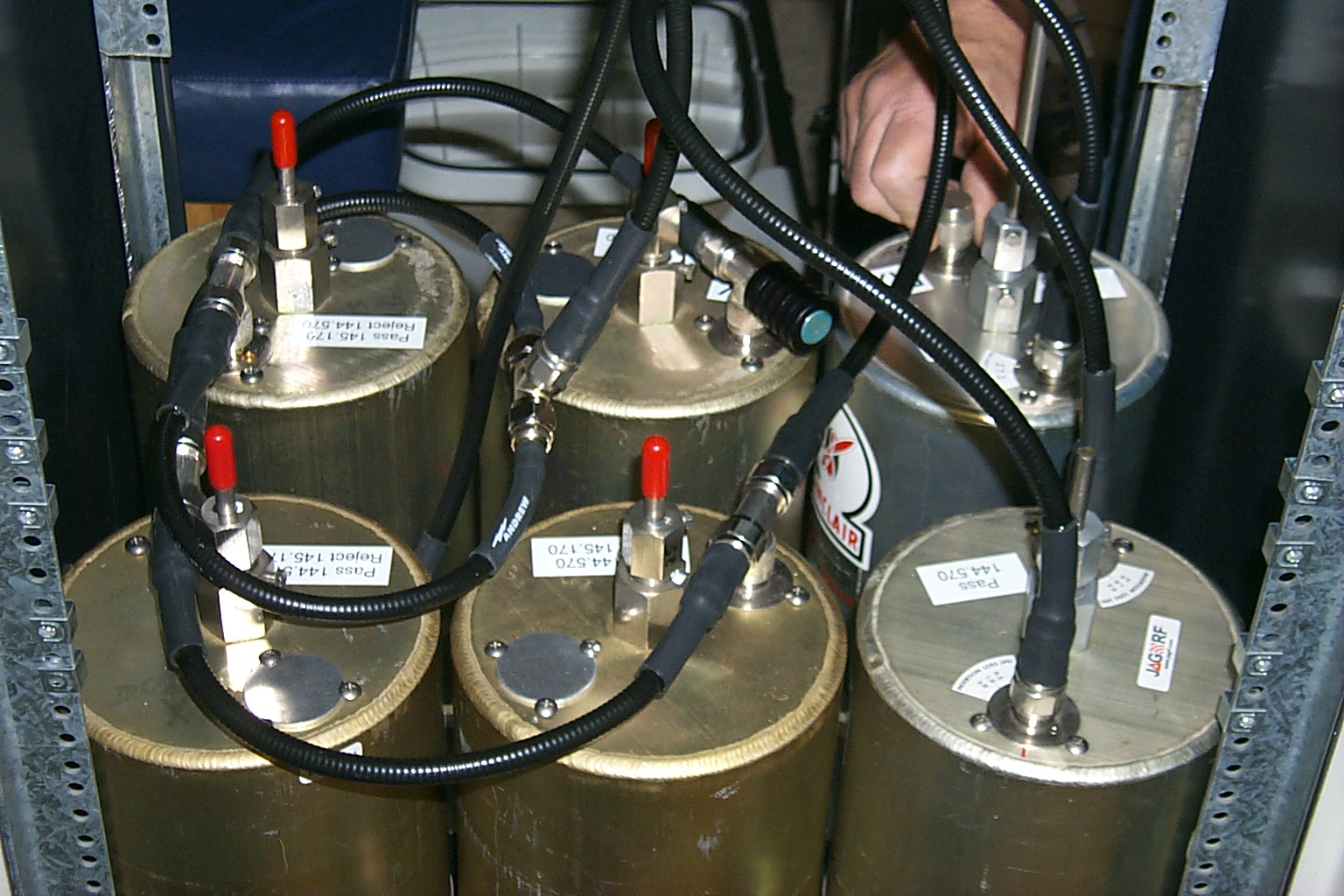
In these photos I had the repeater running on a spare set of large Wacom cavities while working on the upgrade, and then the finished six cavity duplexer on the air for testing with just the RF deck to make sure the new configuration was working correctly.
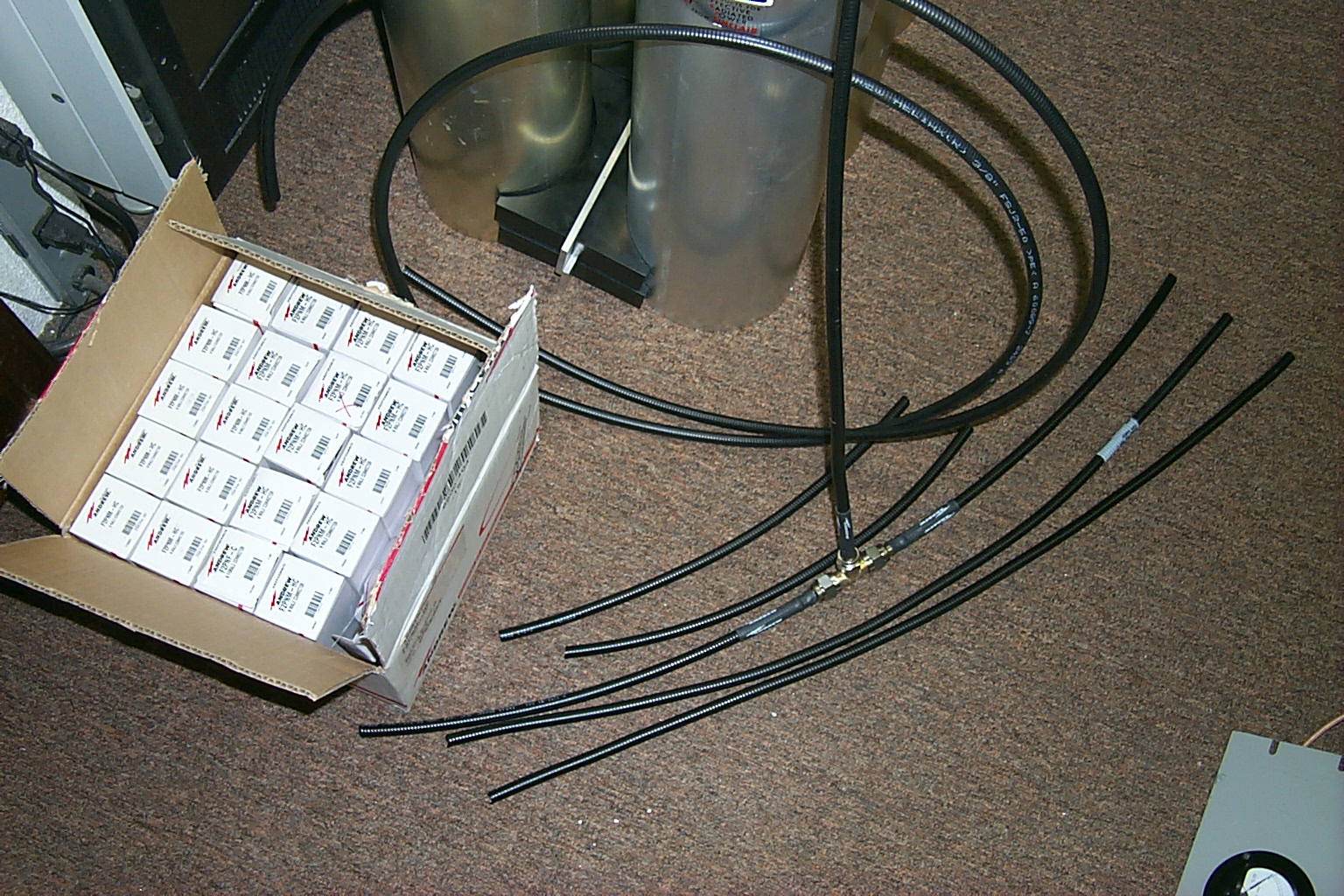
All of the jumper cables making up the phasing harness are made from Andrew FSJ2 super-flex heliax and are cut to the exact length 1/4 wave, 3.4 wave, 1/2 wave, and full wave.


(click on images to enlarge)
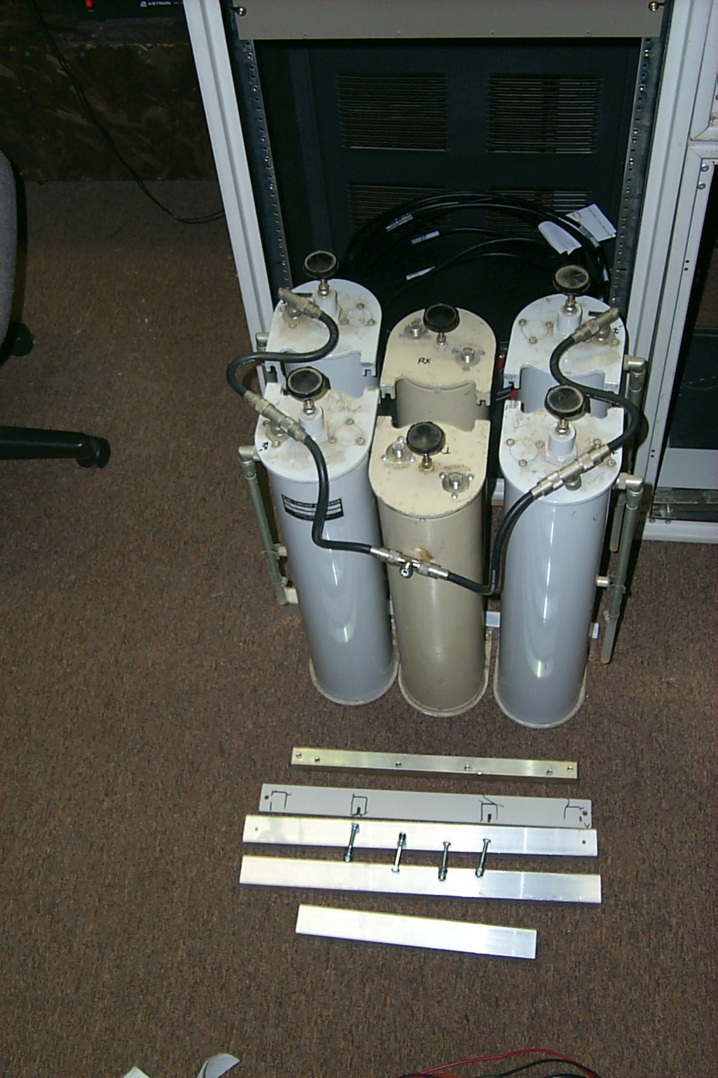
Once the upgraded duplexer had been tested for 48 hours with great success I dragged the hardware back to the house and started bolting everything into the rack cabinet. A third set of mounting rails were fabricated to mount the duplexer and all the hardware was reassembled into the cabinet.
(click on images to enlarge)
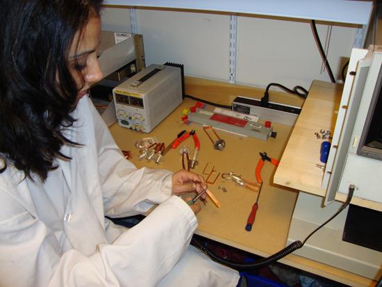
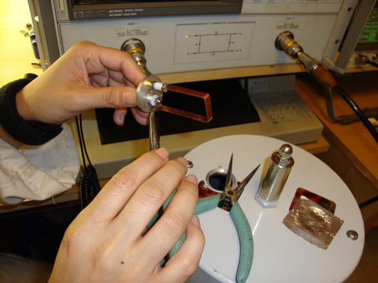
Update May 2010 - More custom JAG Loops!
I had built out the upgraded six cavity duplexer in the photos above in April using the factory Type-N band-pass loops from a larger set of Wacom cavities and the loops had an offset shape that made contact with the mounting screws. After discussing the problem with my friend Jag he fabricated a new set of four band-pass with no offset that will fit better in these smaller cavities.
(click on images to enlarge)
These photos show the new set of JAG band-pass loops and the GLB Pre-selector / Pre-amp that Brian N1BS had donated to the project. I am working on these final steps to complete the upgrades and get all the hardware bolted back into the rack cabinet.
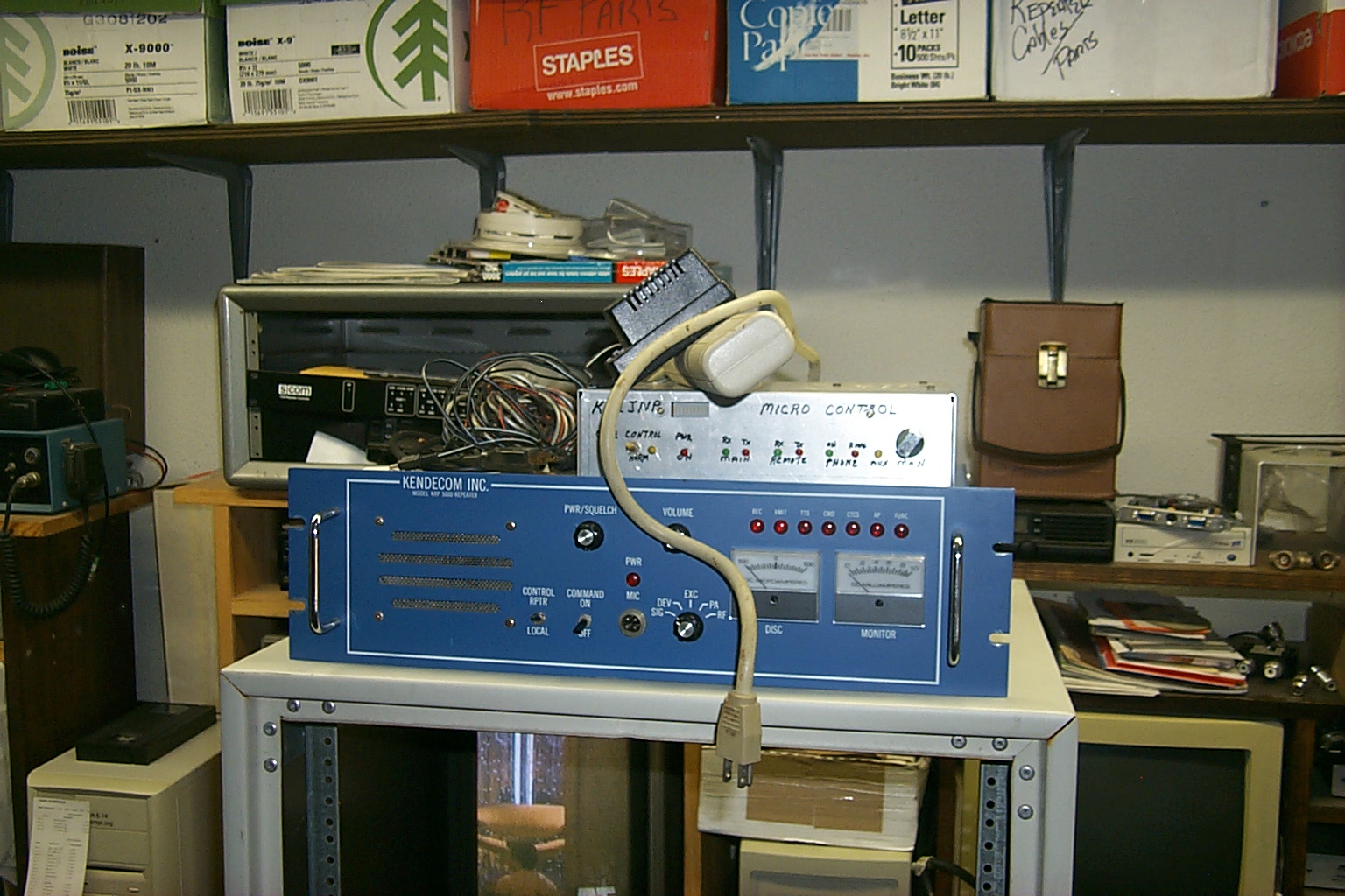
Monday May 31st - HAMCOW High Performance tune-up
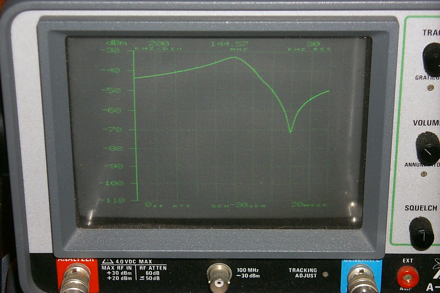
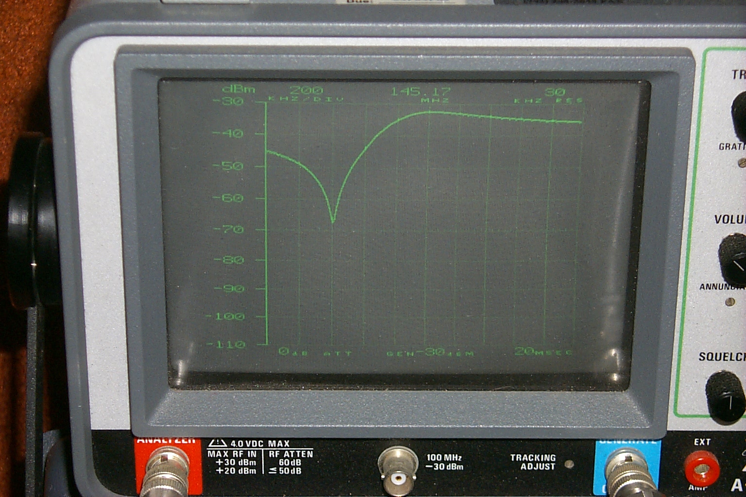
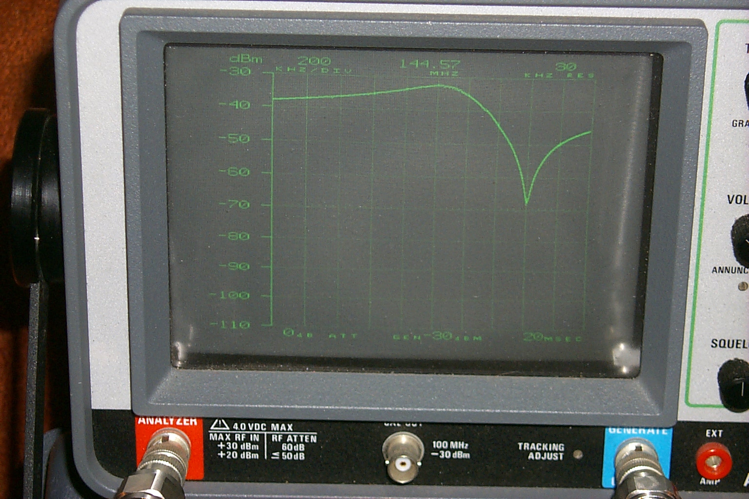
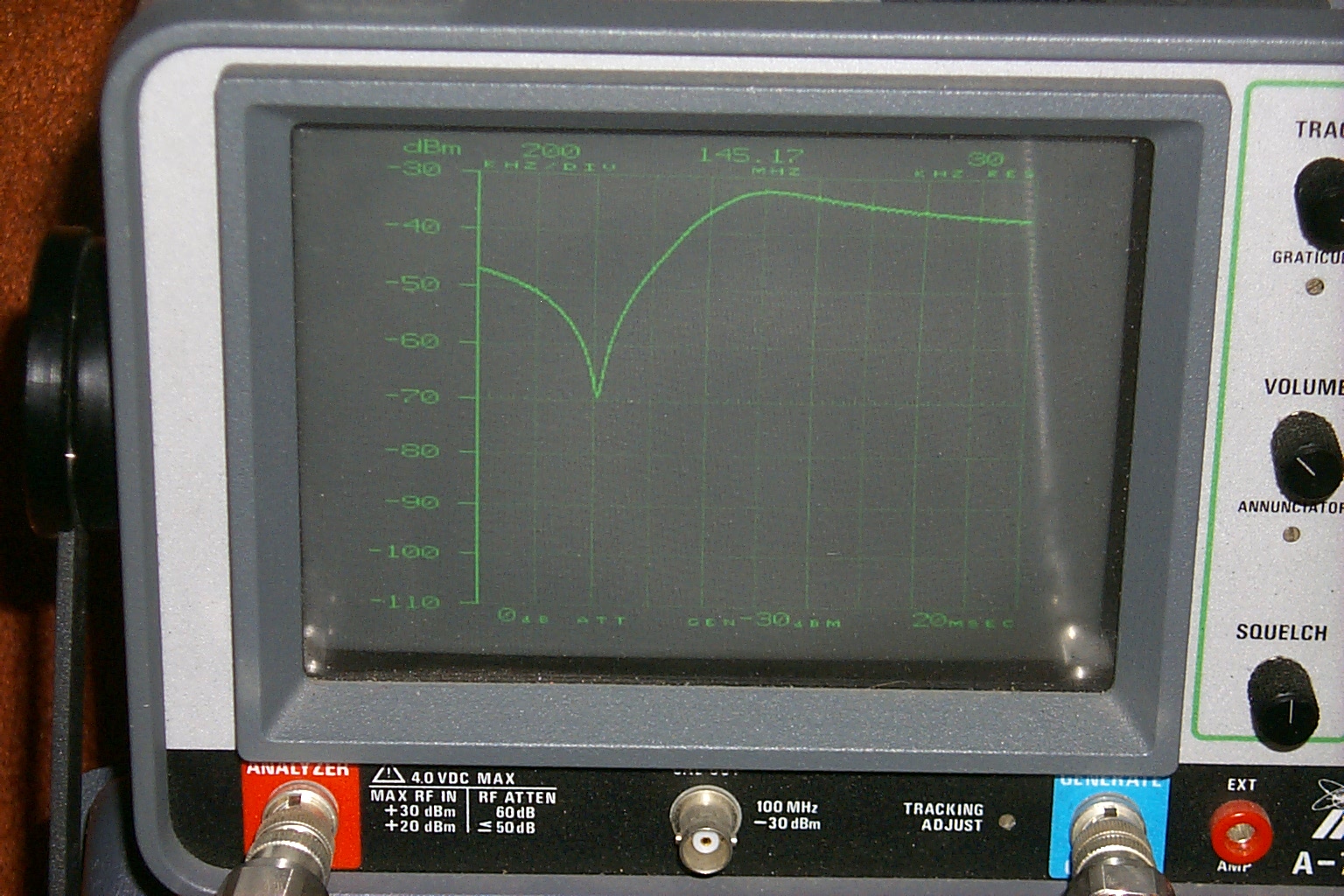
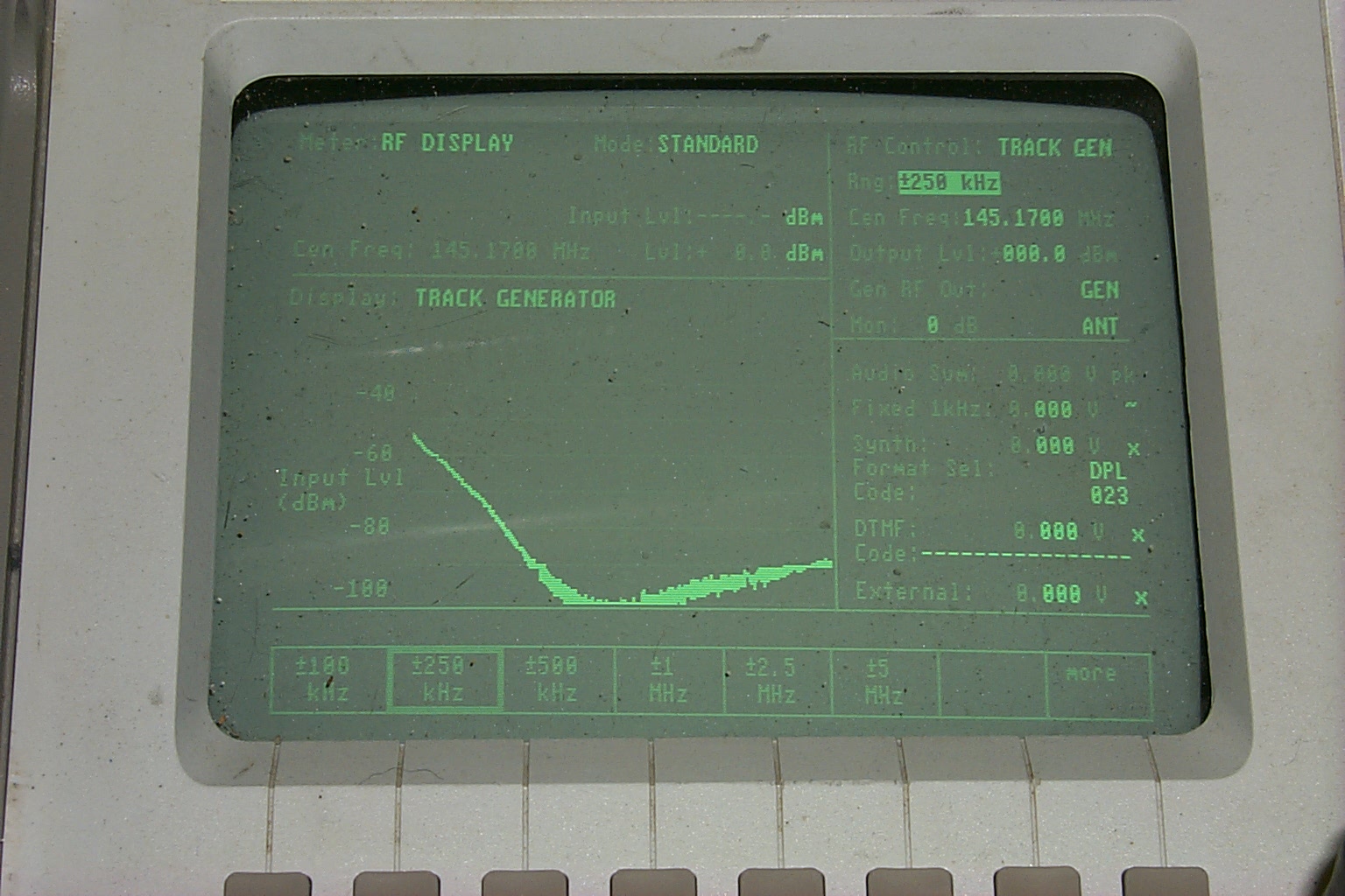
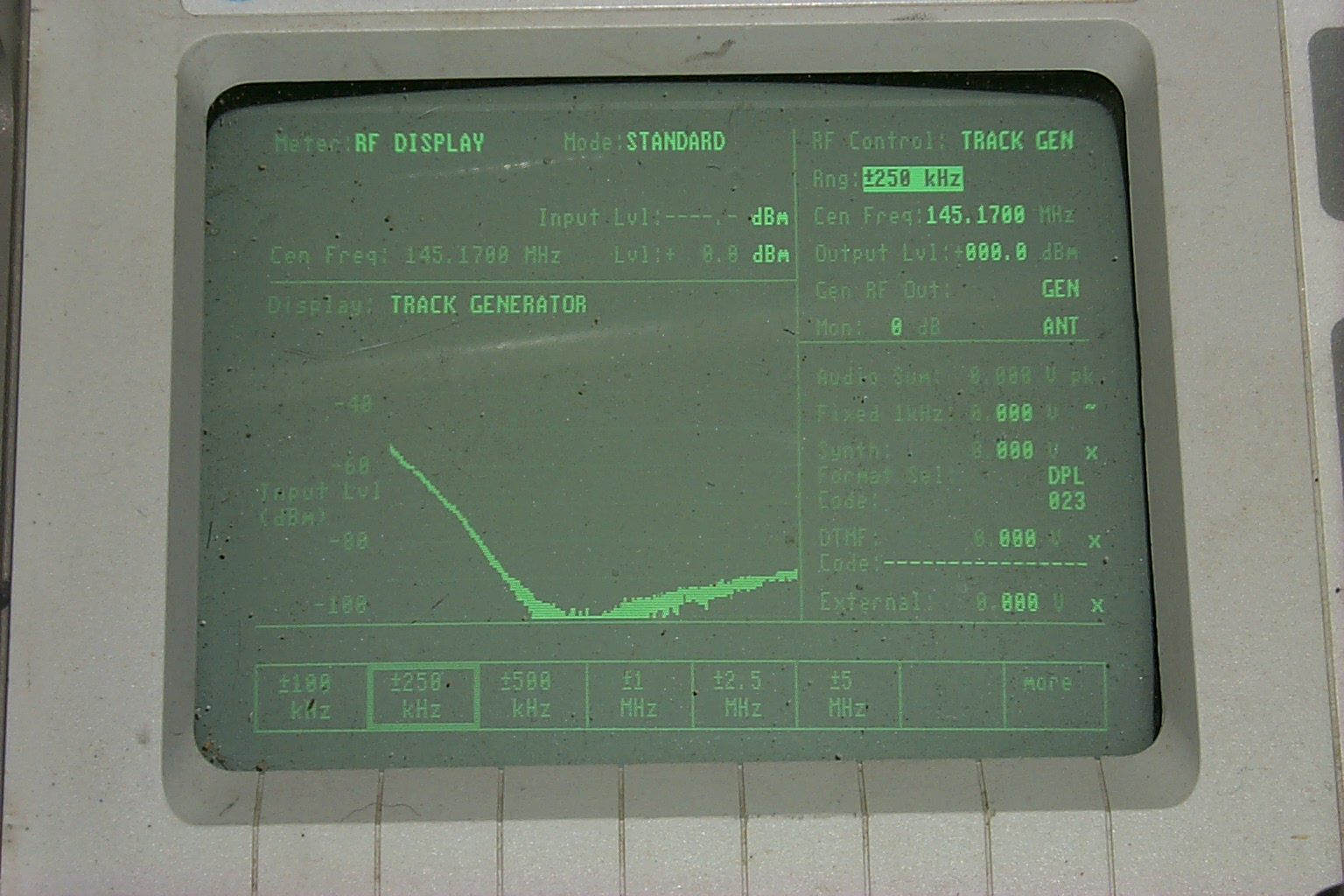
Jag provided some great documentation on the new band-pass loops along with the sweeps preformed in their shop that showed us what we should expect for isolation and insertion loss.
(click on images to enlarge)
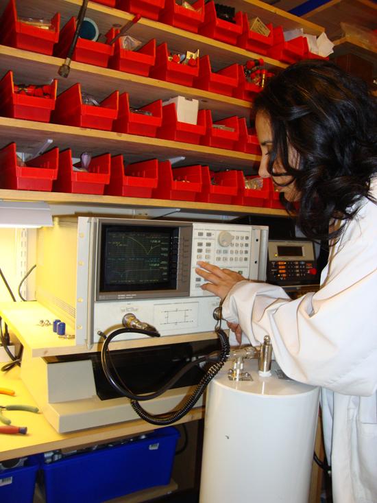
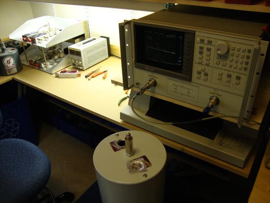
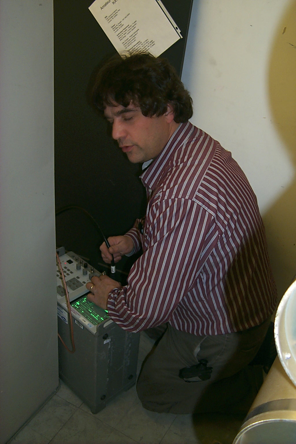
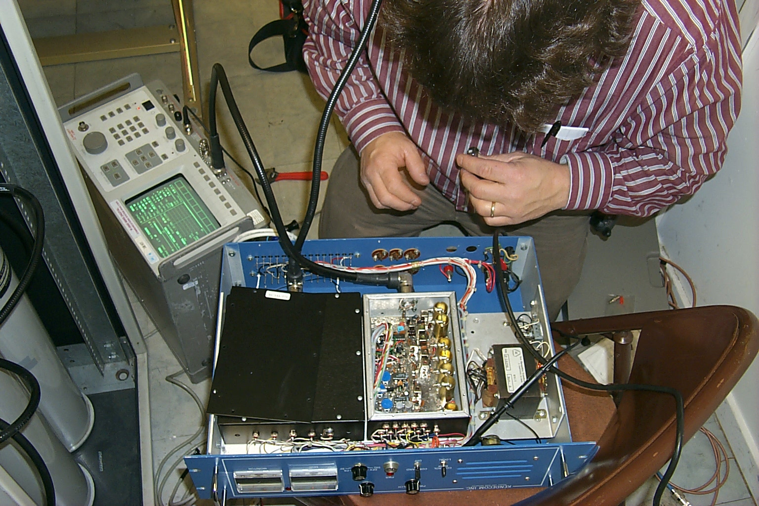
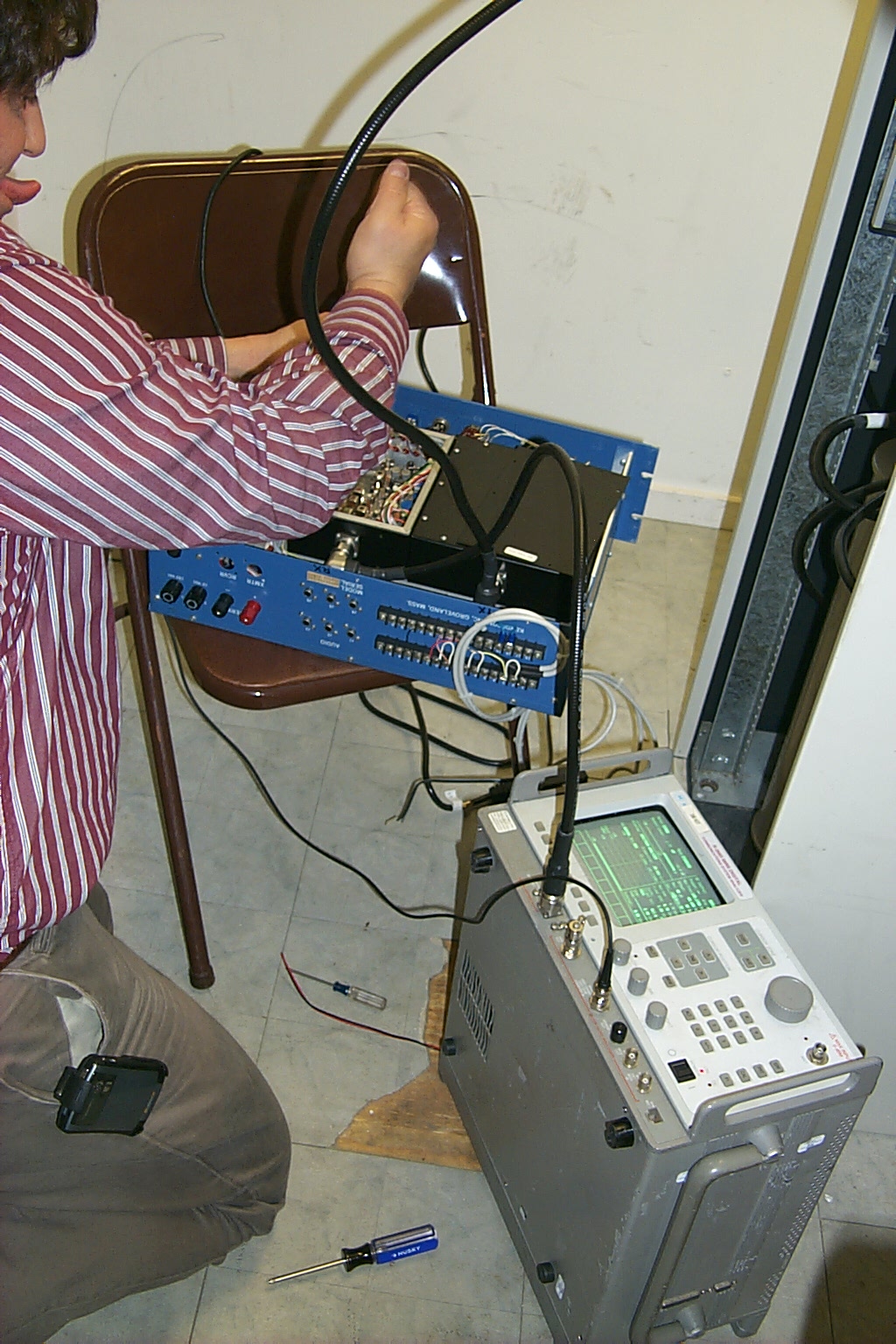
I spent the long 3 day holiday weekend ripping all the hardware out of the rack cabinet and pulling the Wacom offset band-pass coupling loops from the larger cavities and replacing them with the new custom JAG band-pass cavities. I reached out to my good friend Roland N1JOY for help verifying that I had re-tuned the cavities correctly with all the new custom JAG loops and I soon found myself sitting in the HAMCOW going thru another high performance tune-up session.
(click on images to enlarge)
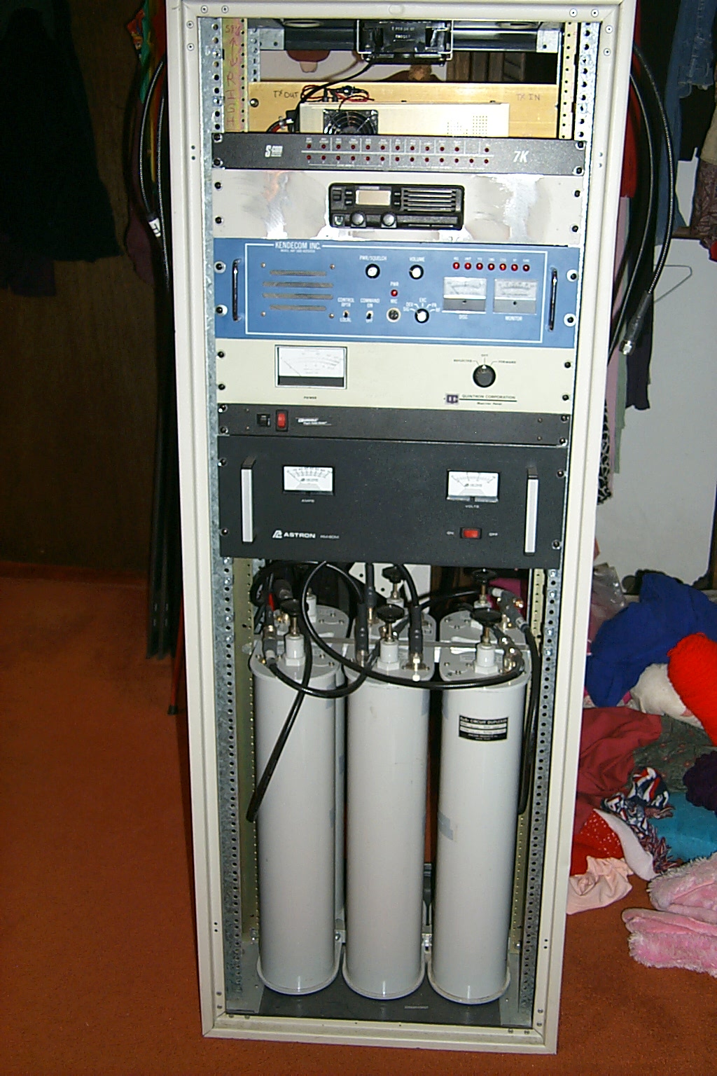
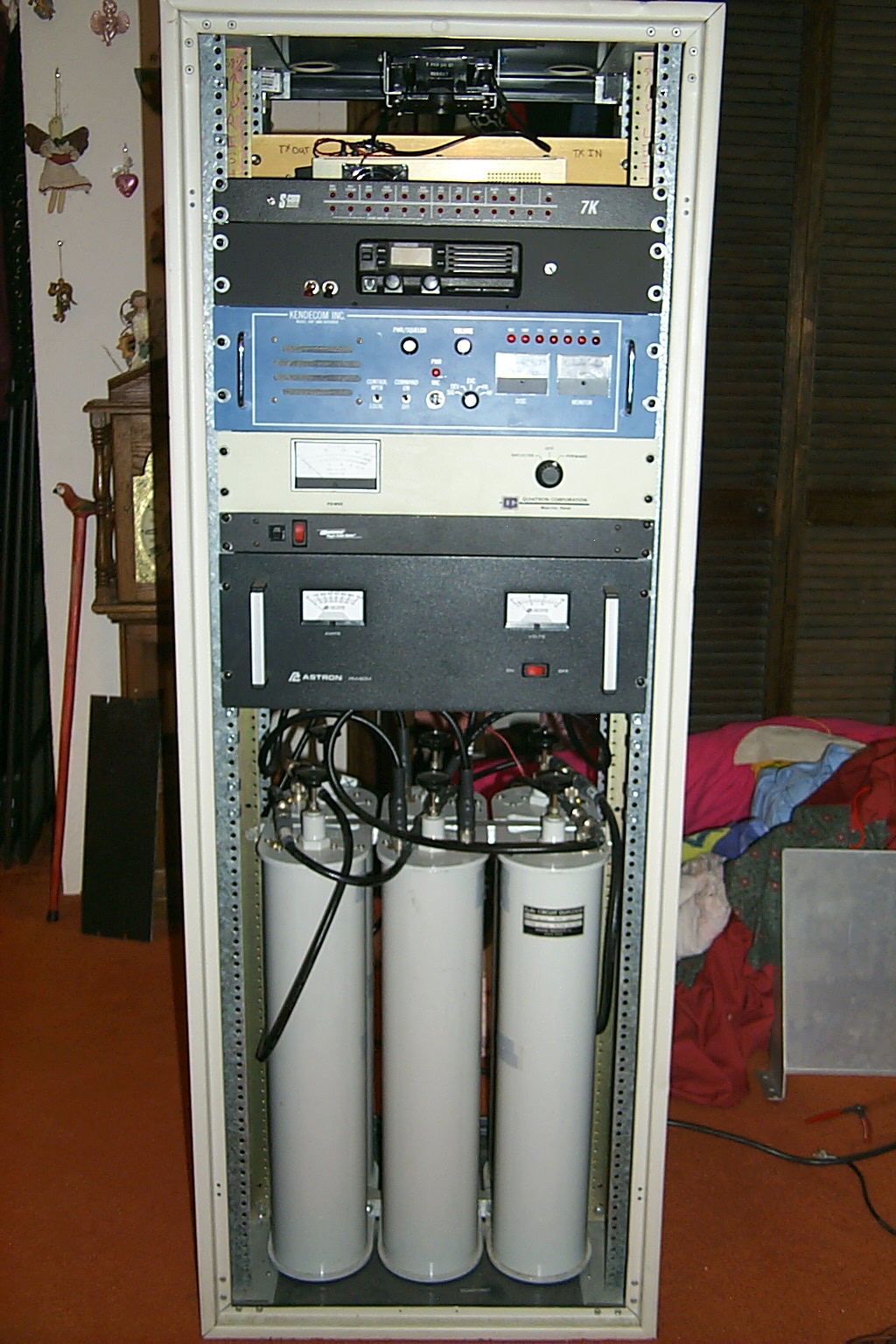
January 2011 - The hardware upgrades continue
After a few months of on the air testing with the new rebuild duplexer it was time to get everything mounted back into the rack cabinet.
Hundreds of hours of work have gone into the rebuild / upgrade the past several months. Each individual component of the hardware that makes up the repeater has been repaired, rebuilt, and upgraded in some fashion.
I replaced all the braded coax and crimped SO-239 / PL-259 cables and connectors with new Andrew FSJ-2 super-flex cable. All cables are %100 super-flex from the RX / TX ports, interconnecting cables, duplexer phasing cables, etc.
(click on images to enlarge)
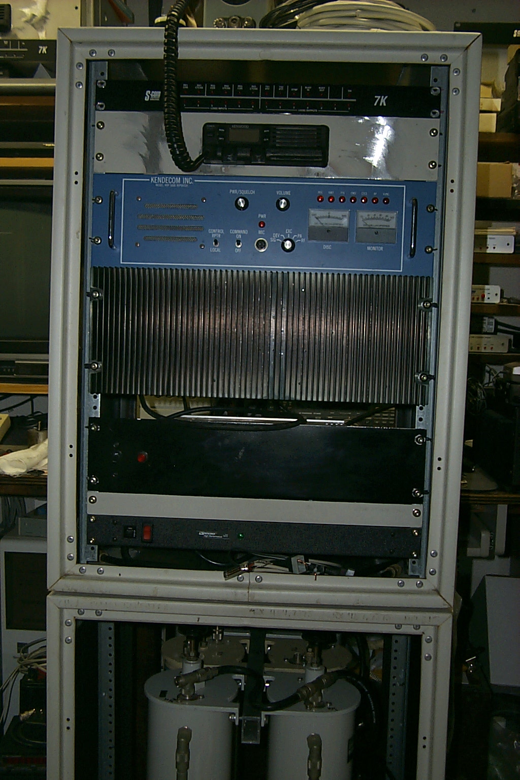
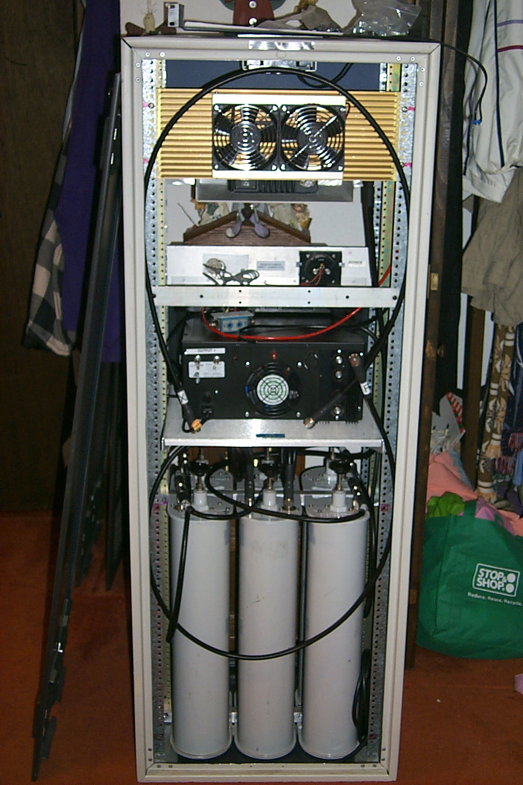
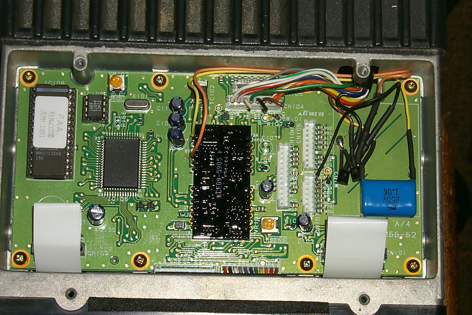
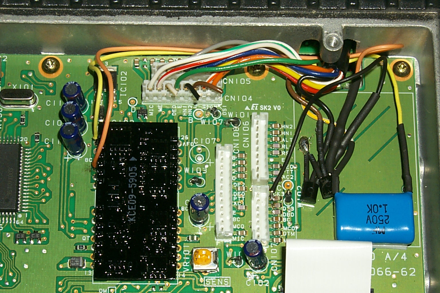
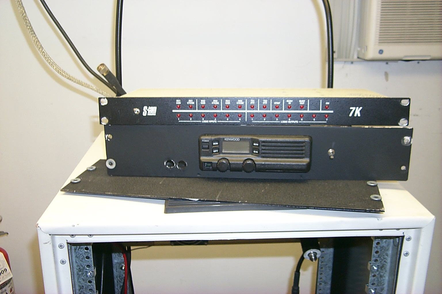
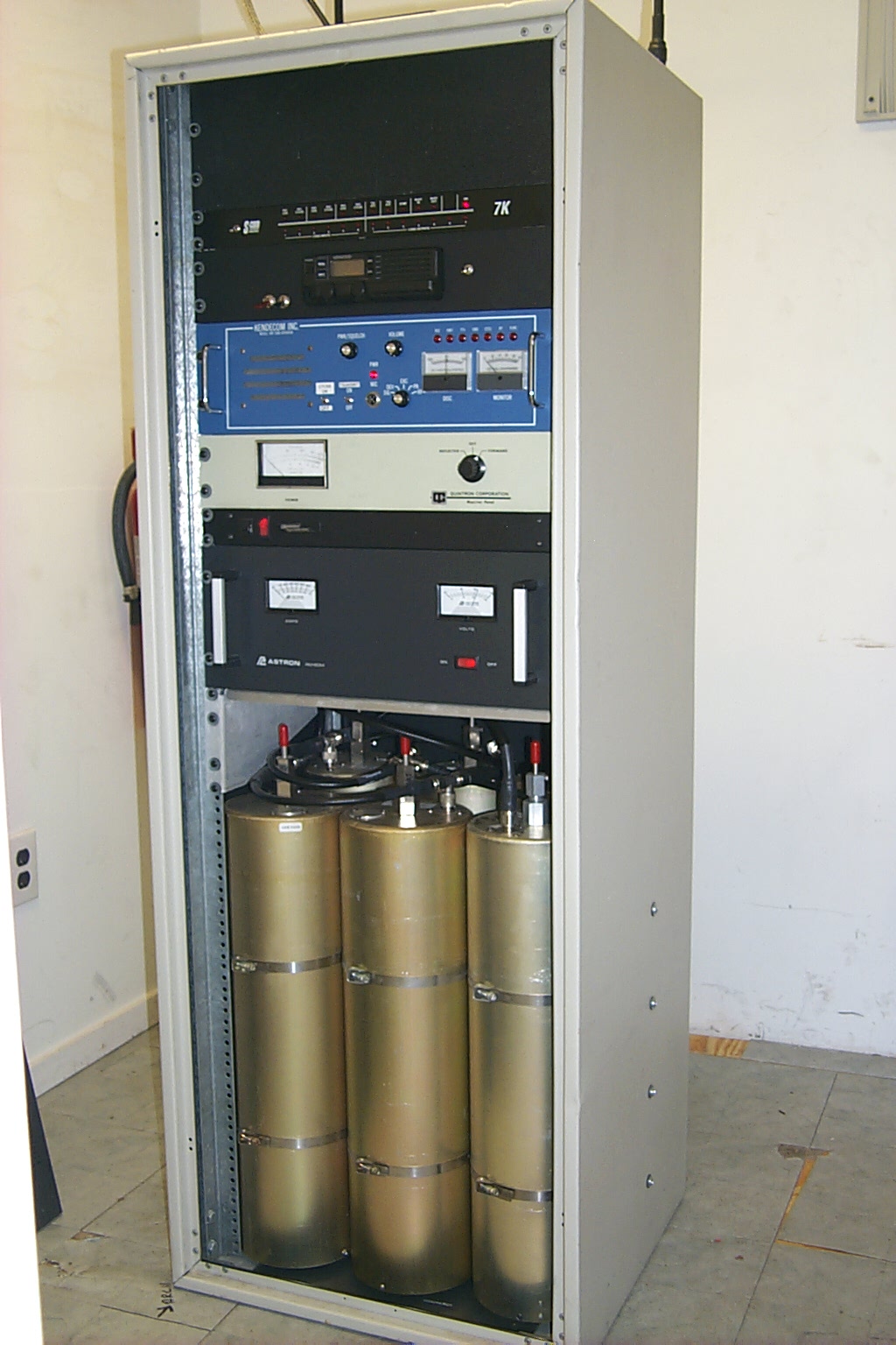
All the hardware was mounted in the new 60 inch cabinet and I made all new cables to connect the S-Com 7K controller to the Kendecom repeater and Kenwood link radio. The 7K received a firmware upgrade and was reprogrammed with all the same basic functions and control macros as all of the other repeaters on the network.
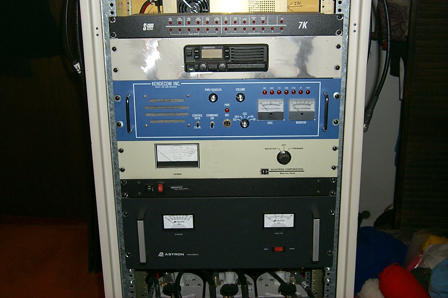
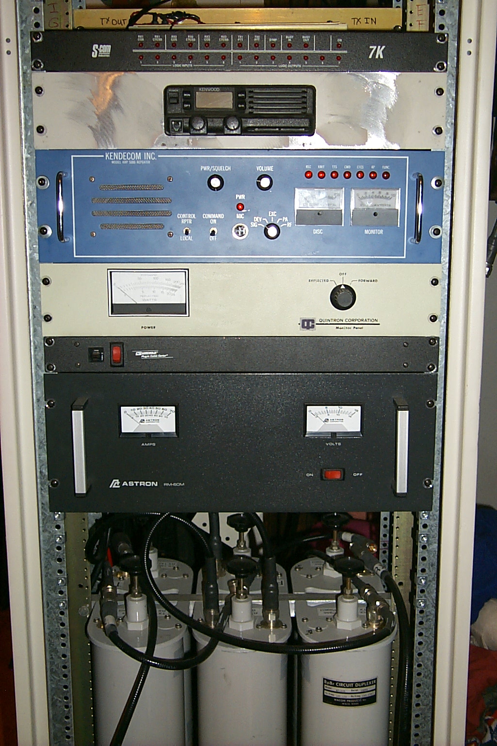
(click on images to enlarge)
The Kenwood TK-830 UHF link radio was given the ABI Labs modifications for that sweet audio, as well as COS and CTCSS signaling for the 7K controller.
In these photos you can see each step as I install the various components to provide the correct signals from the receiver to the controller.
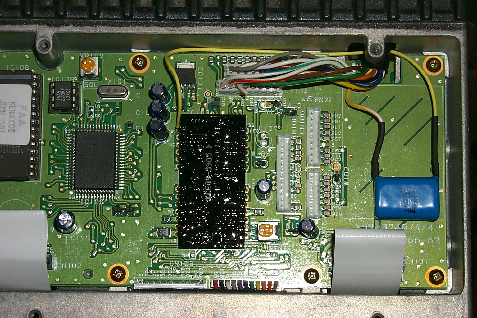
(click on images to enlarge)
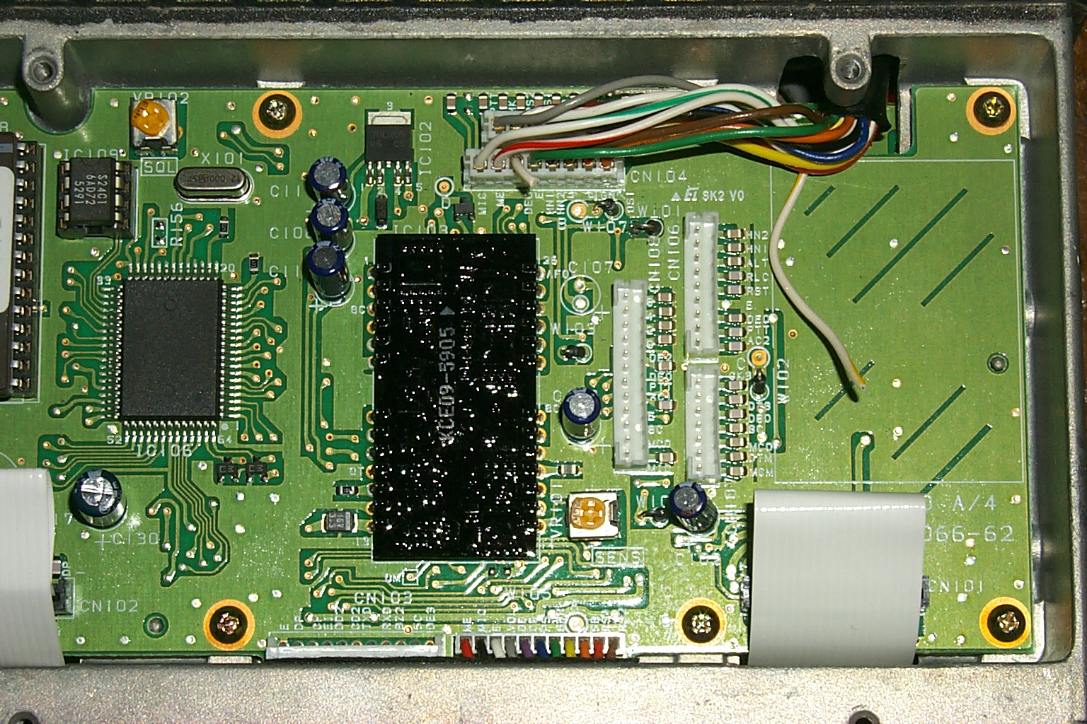
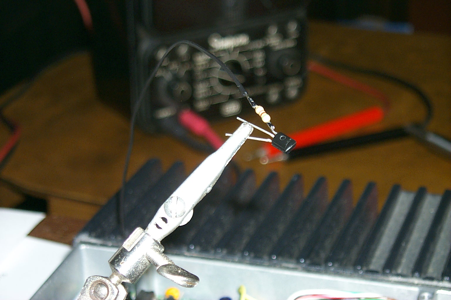
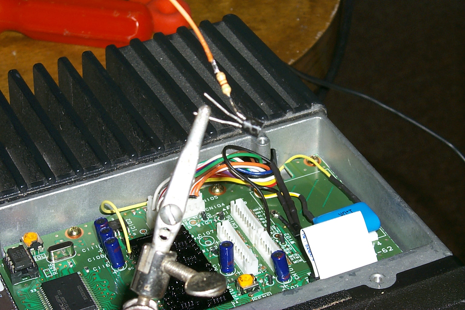
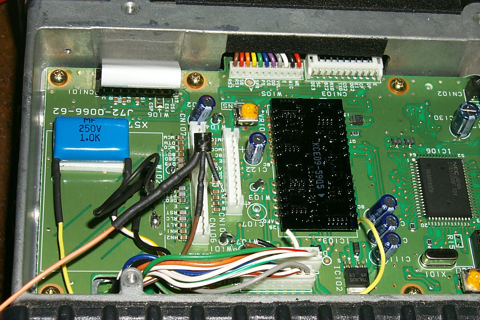
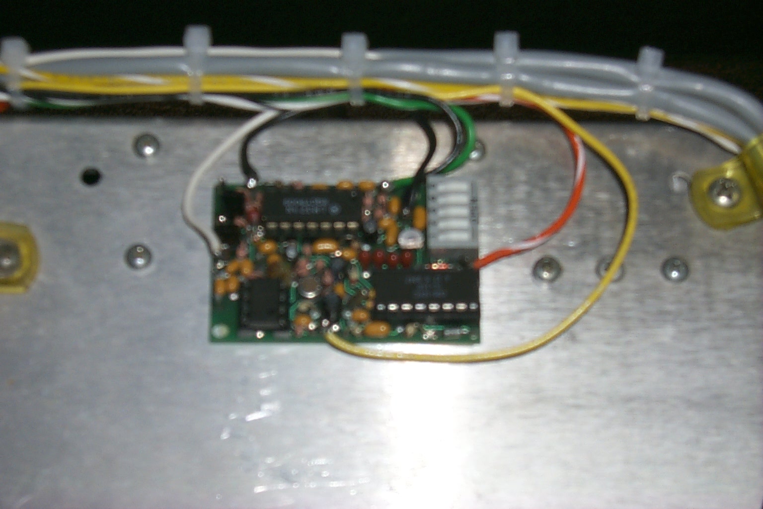
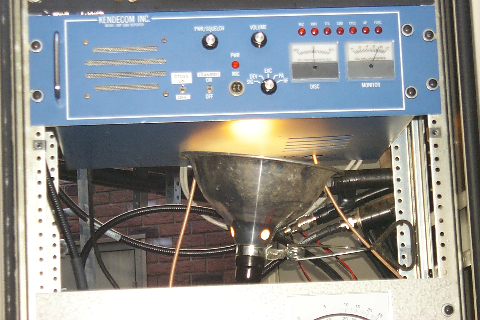
I also added a jumper to the Kendecom receiver to route the discriminator audio to a CTCSS tone decoder for the 7K controller. There was an unused feed-thru capacitor already mounted in the receivers RF cabinet so it was easy to route the audio out to the new decoder board.

(click on images to enlarge)
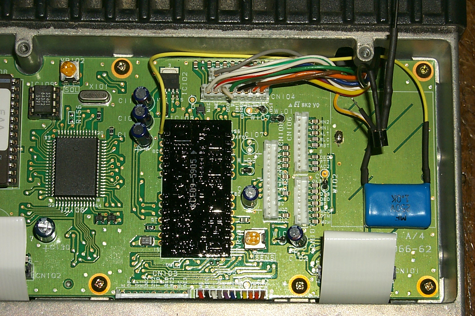
With all the hardware upgraded with new signaling for the 7K controller, and the controller upgraded with the new firmware so the COS and CTCSS singling worked on all three receiver ports, it was time to cut out all the old interconnecting cables and make a new harness to connect the Kendecom and Kenwood to the S-Com 7K controller.
(click on images to enlarge)
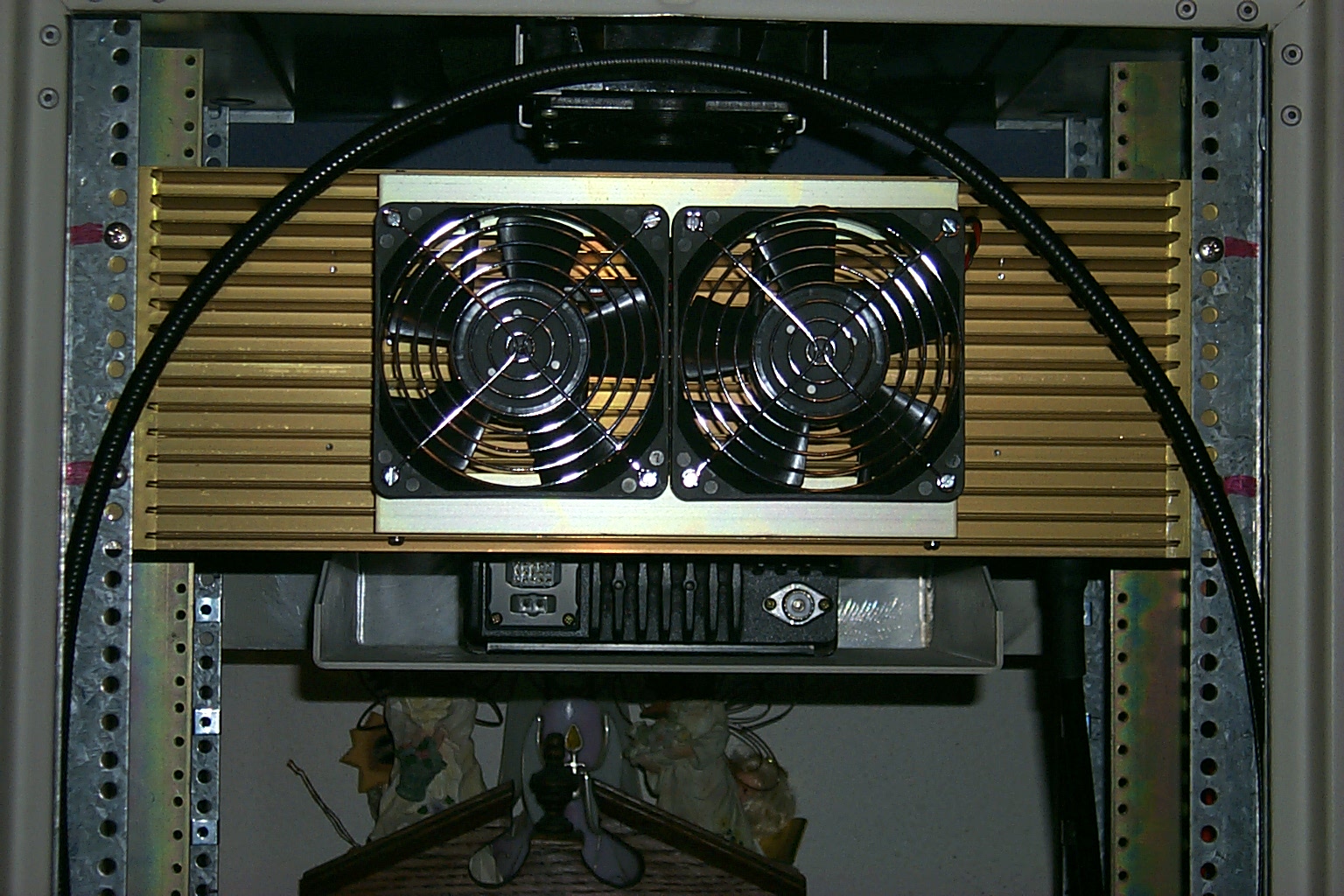
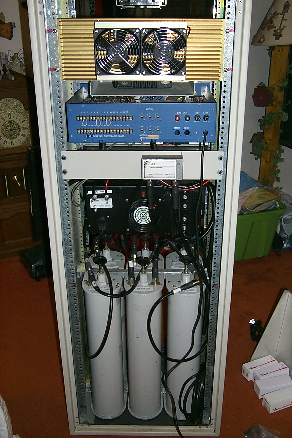
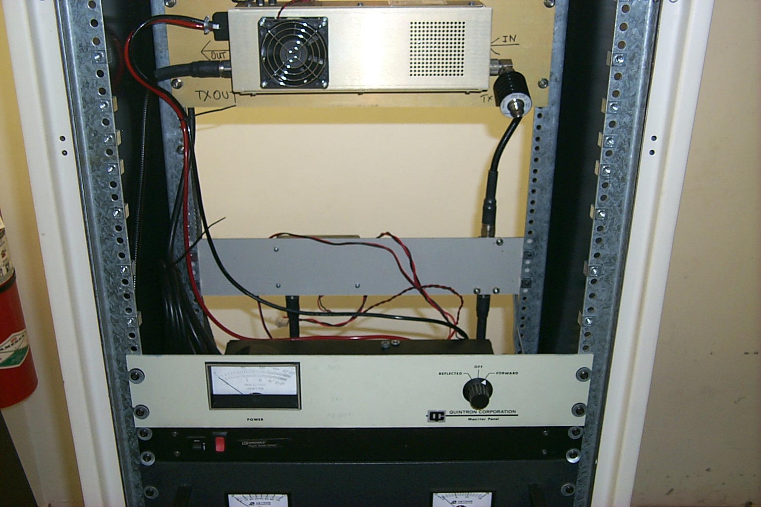
Then I just needed to paint a few parts and bolt everything back into the new rack cabinet. I also added a support plate to provide a mounting location for the GLB PreSelector / PreAmp and the power sensor for the rack mounted VSWR meter.
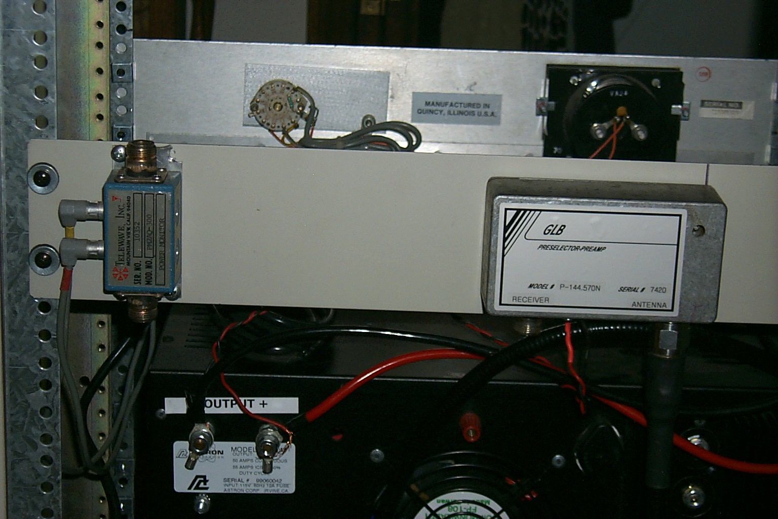
(click on images to enlarge)
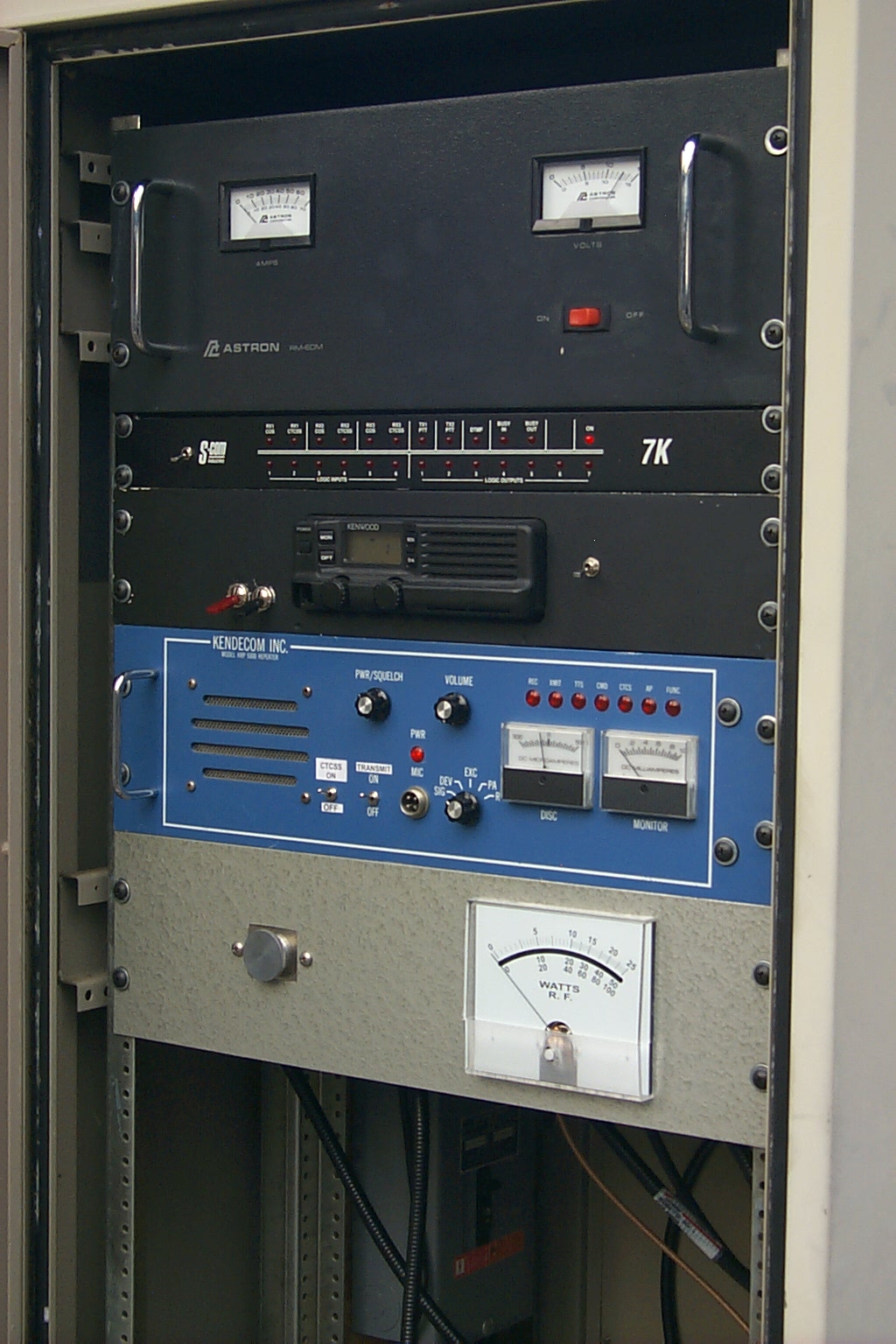
Saturday February 26th 2011 - The Rebuild is Complete!
The finished repeater hardware on the air at my house for some more testing just hours before Dad & I got everything loaded into the Big Blue Beast and dragged it back to the repeater site...
(click on images to enlarge)
When I helped Bill KA1JNP this repeater on the air back in 1987 I never would have imagined that 25 years later we would be doing such an extensive rebuild but I am sure glad that we did. My only regret is that we lost Bill a few weeks before the project was finished. Bill did see most of the project unfold and did get to see the HUGE new JAG dipole array mounted on the tower, and I know he was excited about our new northern node on the network.
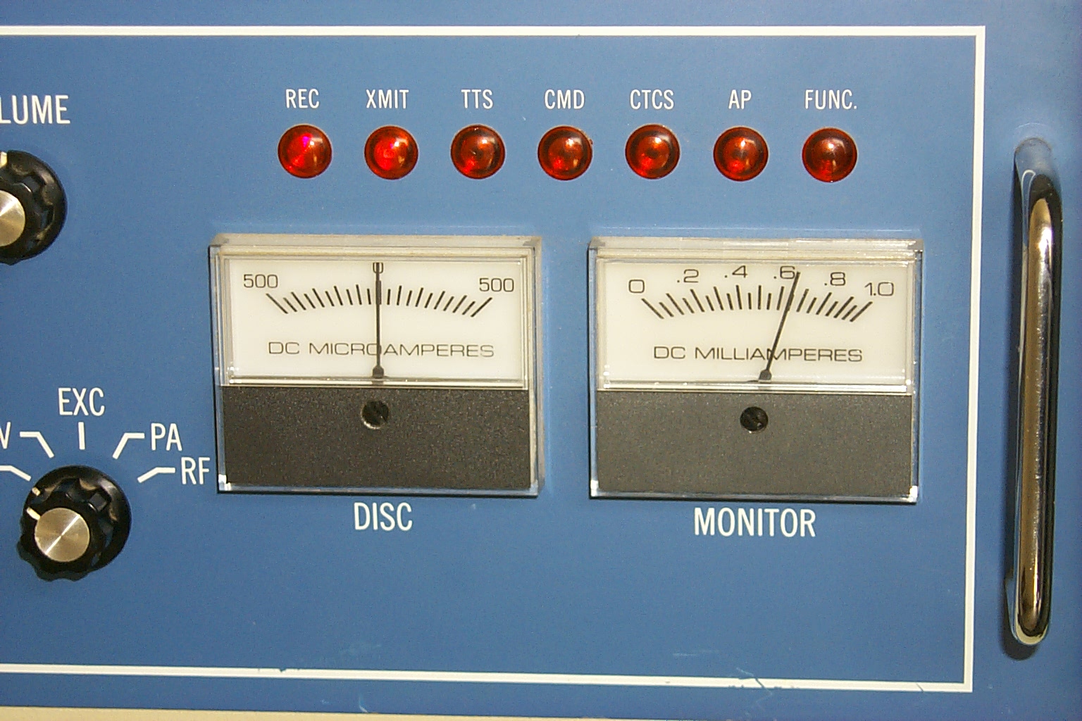
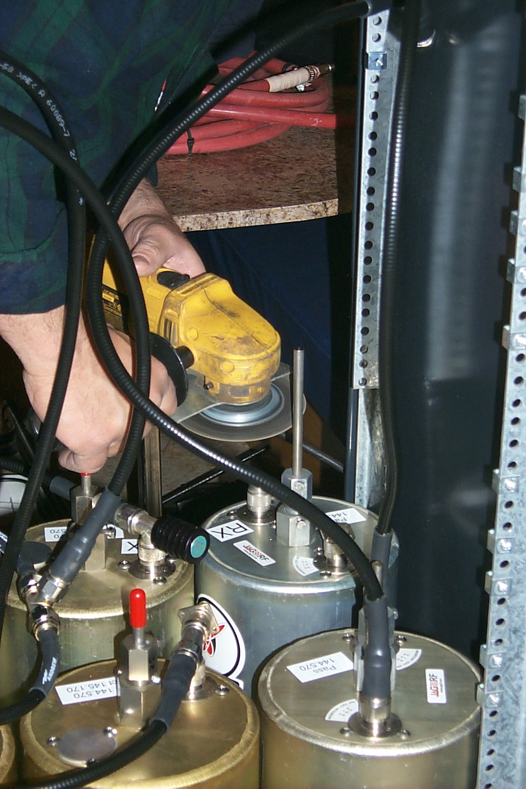
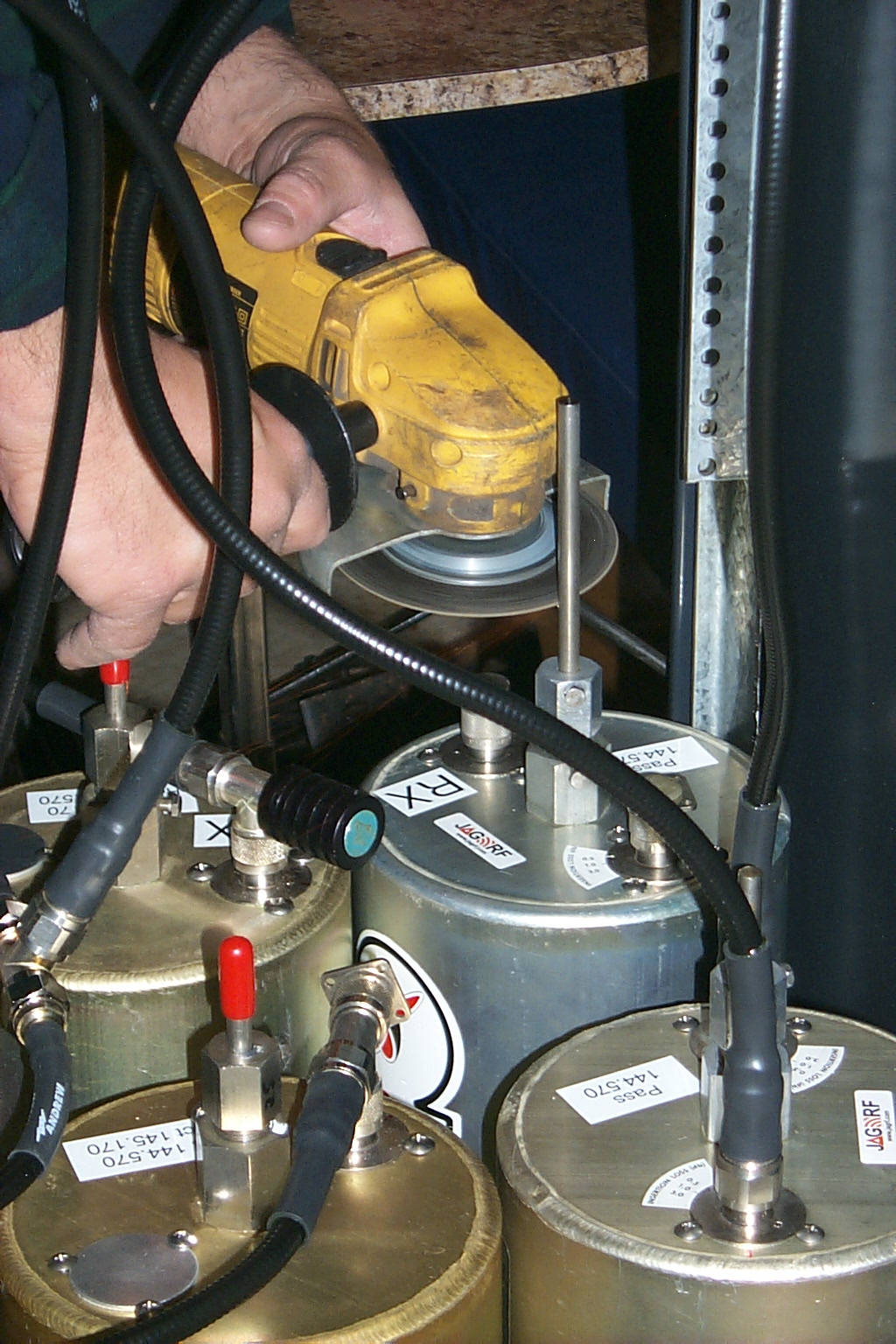
Wednesday Morning March 2nd 2011 - Something is not right...
After deploying the repeater on Saturday it was obvious that something was not working correctly. The transmitter was getting into the receiver and adversely affecting the receiver performance.
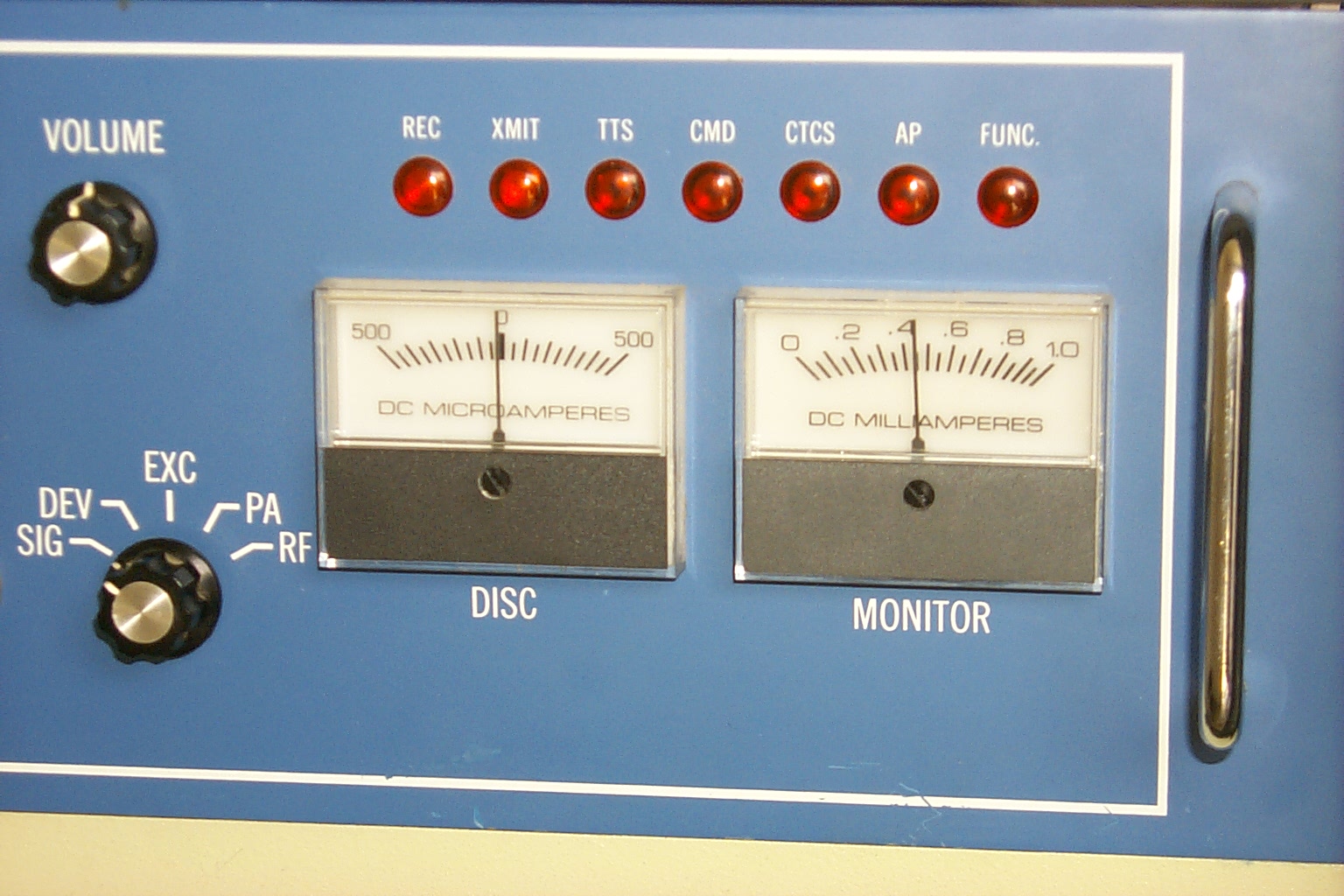
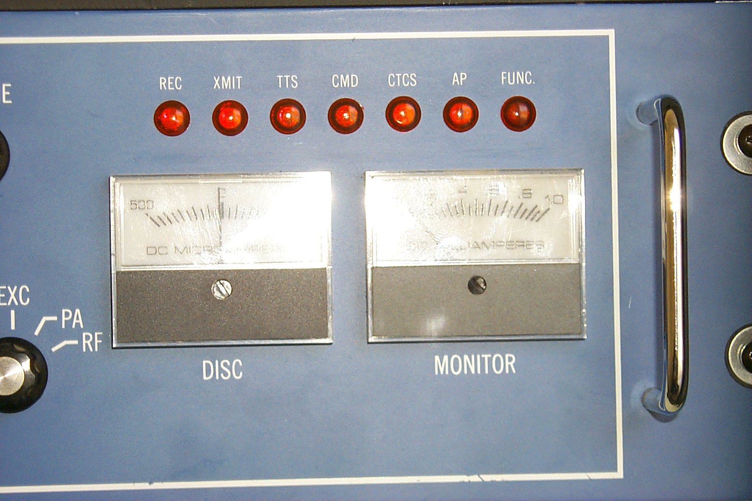
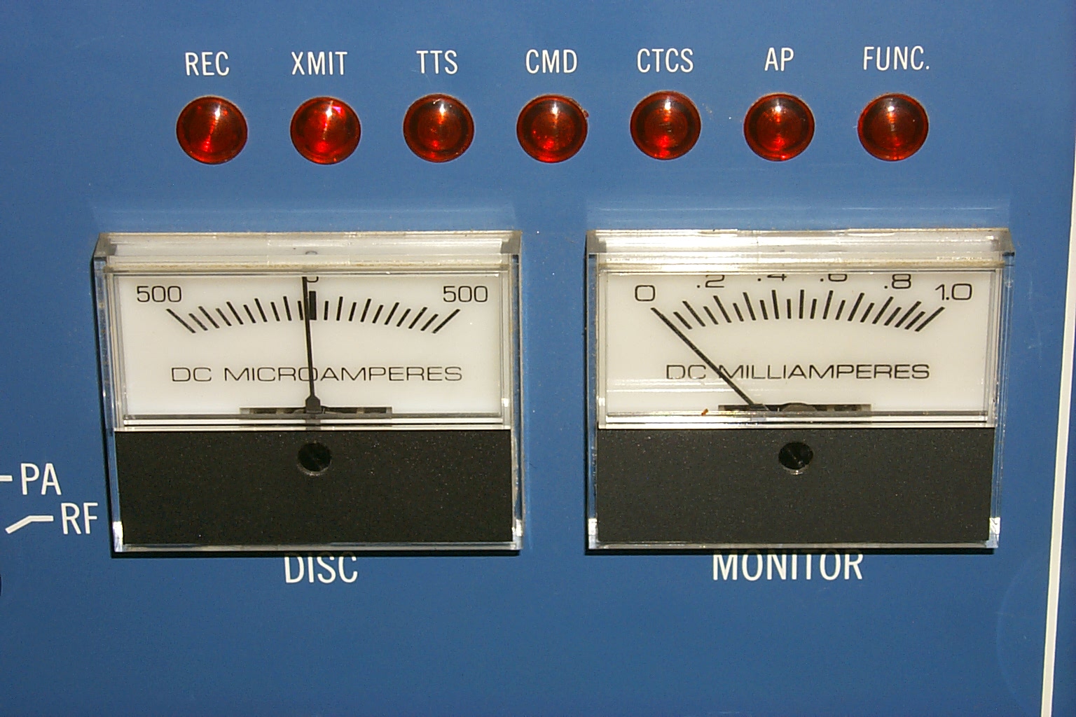
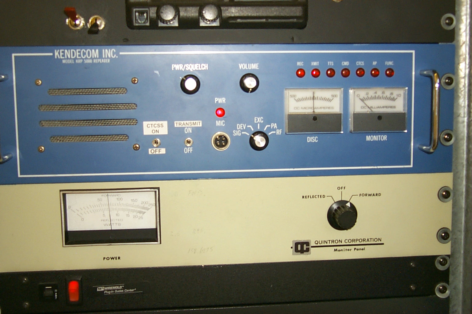
In these two photos you can see the monitor meter on the Kendecom indicating the signal on the receiver. In the left photo the transmitter is OFF and the receiver is idling at approximately .45 units and in the photo on the right the transmitter is ON and the receiver is seeing .65 units.
NOT GOOD
(click on images to enlarge)
I quickly tuned up a JAG custom filter cavity and ran back to the site on my lunch break and dropped an extra pass / reject cavity in line with the two TX cavities in the duplexer.
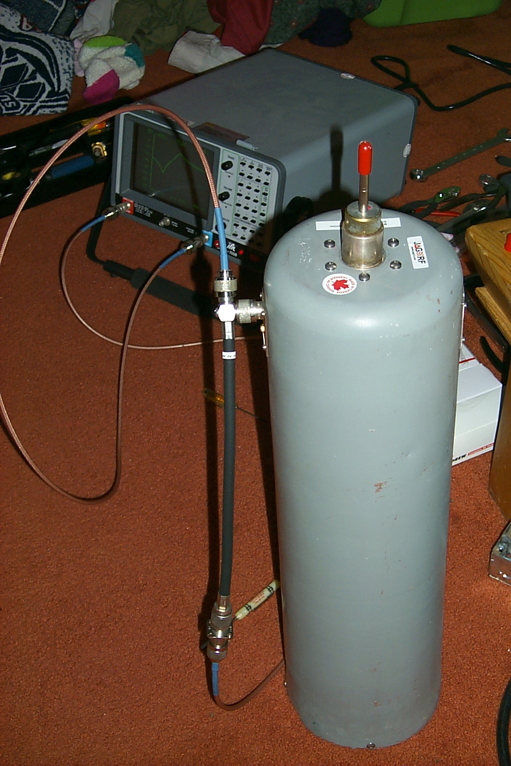
(click on images to enlarge)
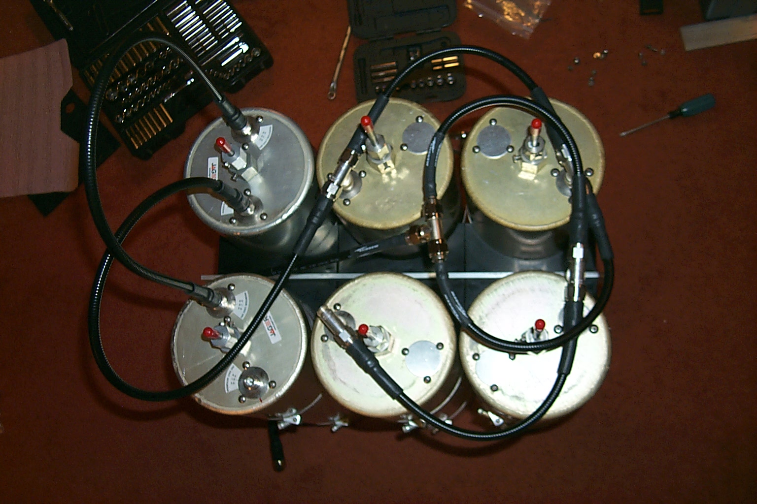
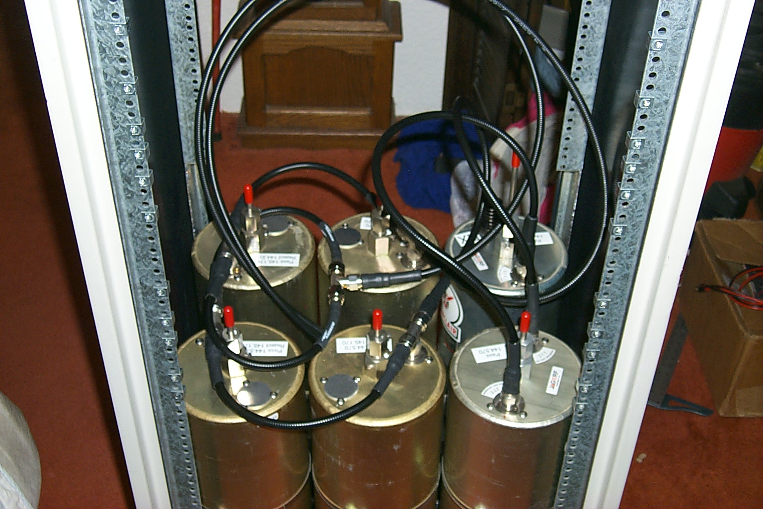
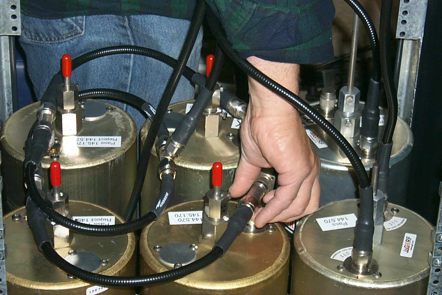
In these photos you can see the six cavity duplexer and then the extra JAG pass/reject filter cavity added in line with the two Wacom cavities in the duplexer.
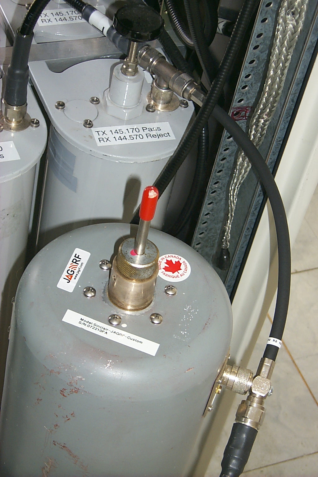
(click on images to enlarge)
Wednesday Night March 2nd 2011 - Look at that Grass!
After work Roland and I pack up the tools and test gear, dragged everything to the site, and ripped the repeater apart... *again*
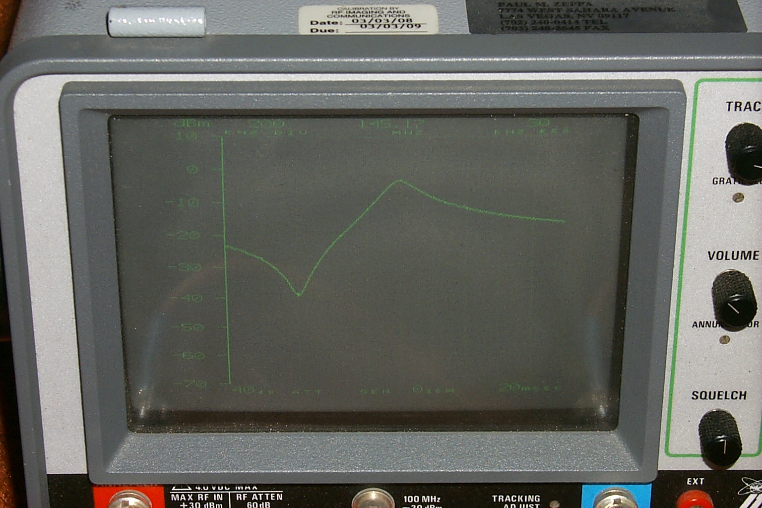
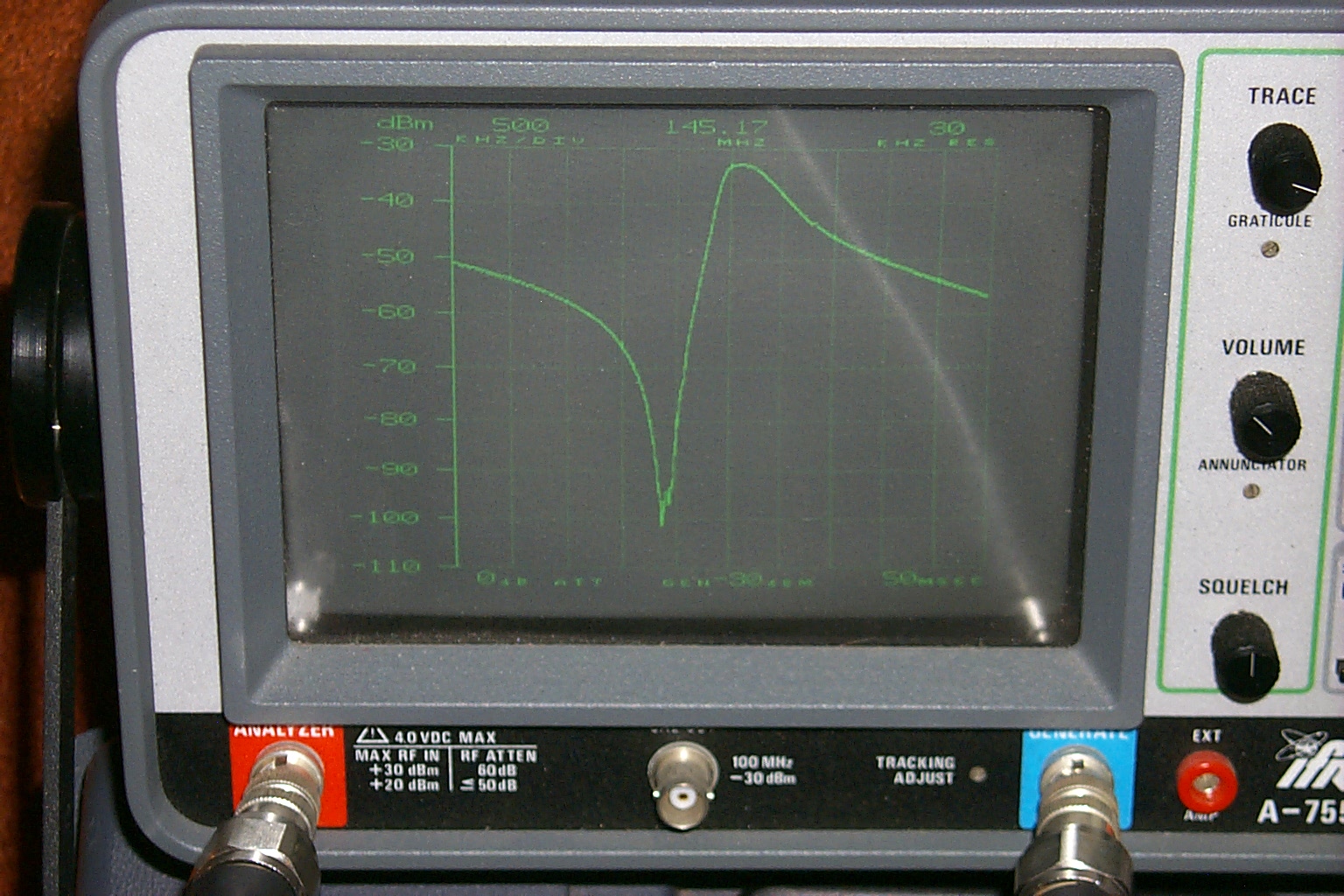
Once we were onsite with the test gear, Roland took a quick look at the repeaters output with the spectrum analyzer... Instead of the nice clean (single spike) we were looking for at 145.170 MHz, we saw several hundred little spikes all over the 2 meter band...
NOT GOOD!
(click on images to enlarge)
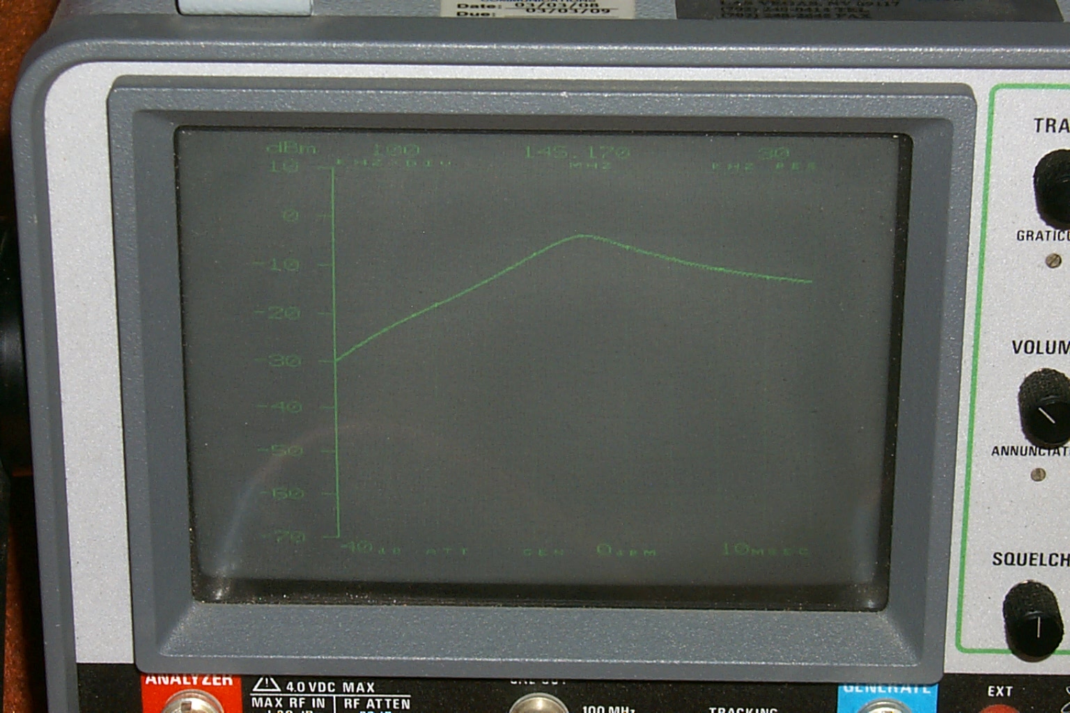
Problems solved...
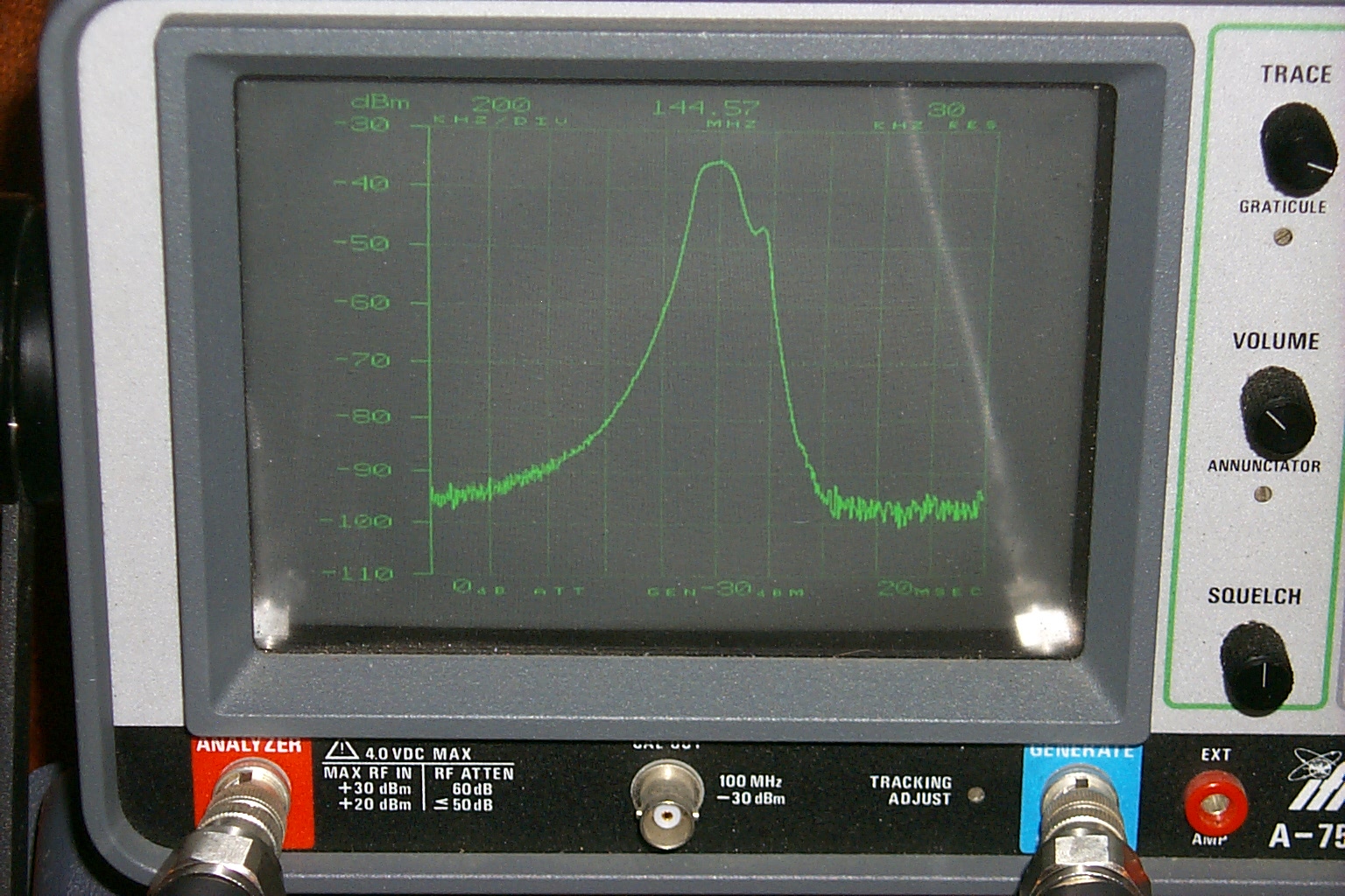
After three hours of troubleshooting we were able to identify and correct several issues. The Kendecom transmitter had been producing spurious emissions, that was fixed and the transmitter was retuned. The receivers front end filtering was also re-aliened and a dirty trimmer pot was cleaned which made a substantial improvement in the receivers performance.
In these photos you can see N1JOY working on the Kendecom receiver and duplexer.
(click on images to enlarge)
By the time we had found and correct all the issue we were both tired and just wanted to quit for the night. So we left the Kendecom on the air as a stand-alone repeater running on the internal basic controller and packed up for the night.
Friday March 4th 2011 - It's working...
After a brief burn in, running the repeater in stand-alone mode, we were able to see a remarkable improvement in the repeaters receiver performance. Stations were checking in and giving us great signal reports from more than 30 miles away and the issues with the transmitter causing receiver desense we gone.
I packed up my tools and test gear and made the trip back to the site on Friday to mount all the other hardware back in to the rack cabinet. The UHF link radio, 7K controller, support shelf for the power supply etc. all went back into the rack and the repeater was back on the network.
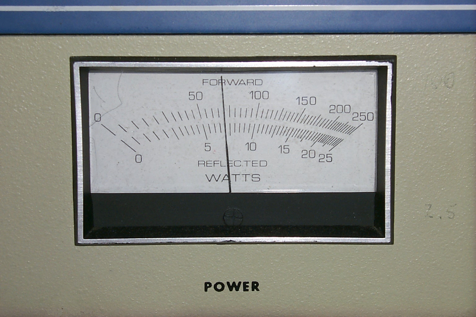
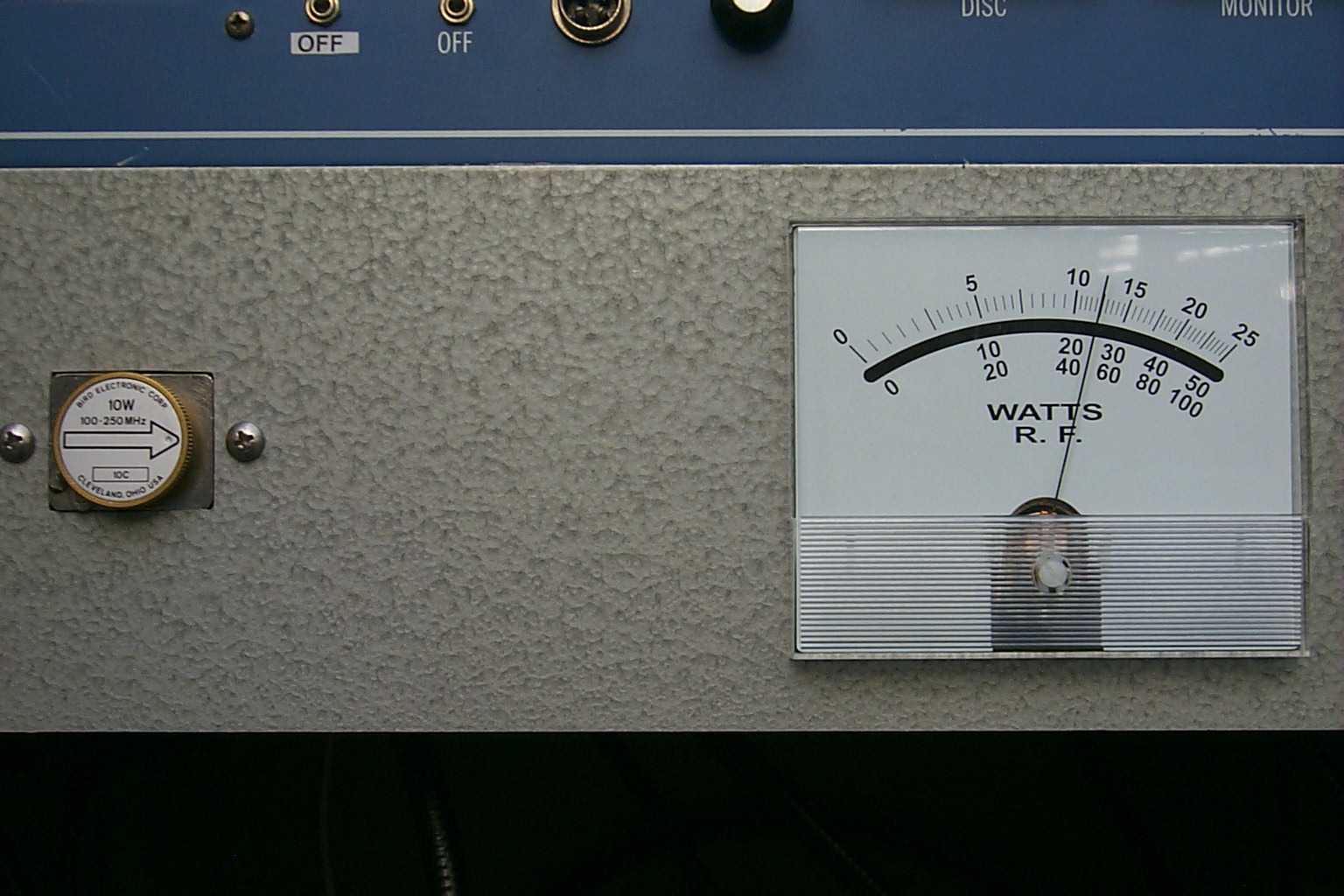
With all the work from Wednesday night the receivers signal meter now sits idle below .01 even with the transmitter online. The repeater output power is a nice clean 54 watts.
"NO GRASS"
(click on images to enlarge)
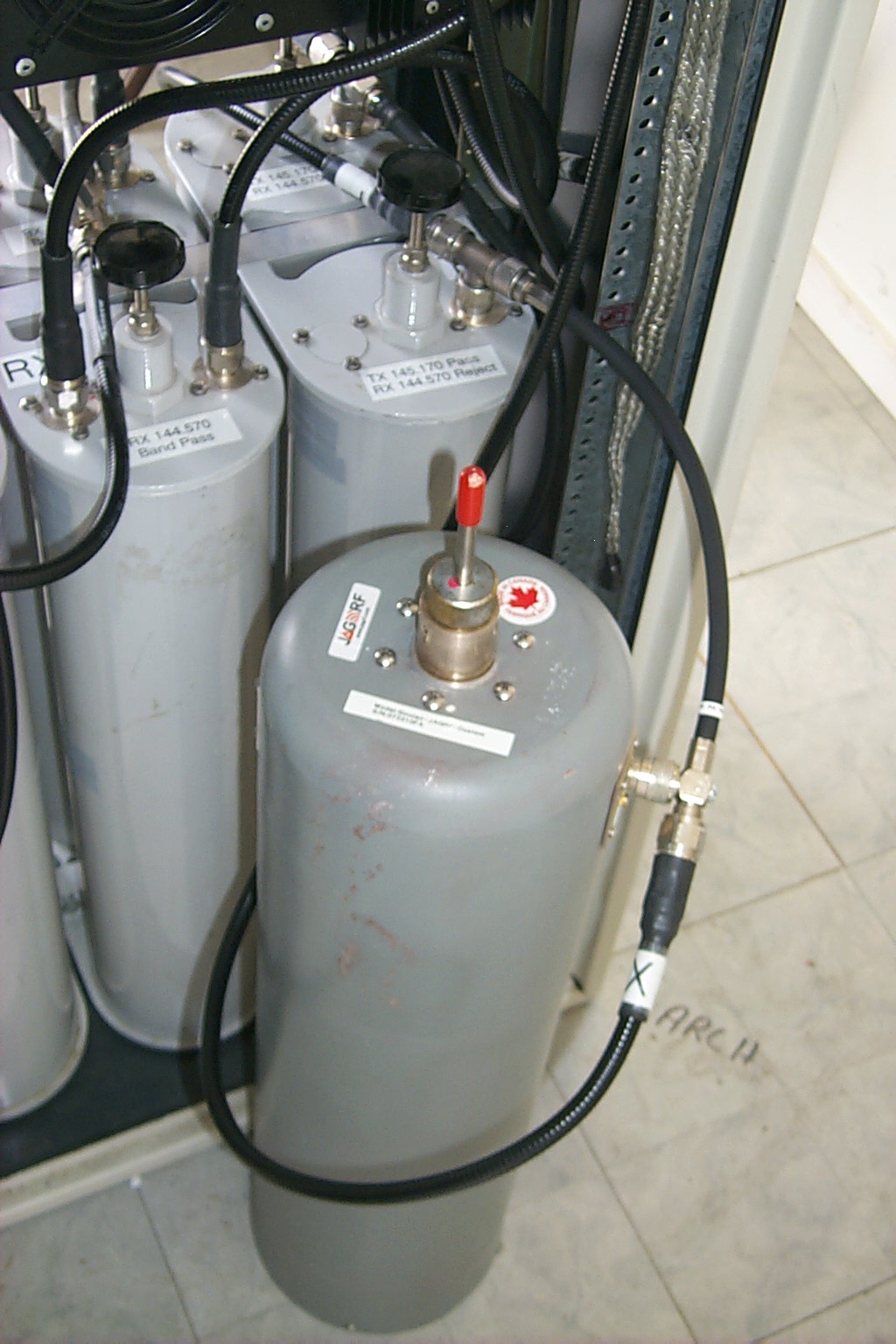
We left an additional pass / reject filter cavity in line with the two TX cavities on the duplexer for the additional isolation needed. When time allows we will head back to the site to make some final adjustments to the duplexer and experiment with a different Preamp on the receiver.
(click on images to enlarge)
We fixed it so good, we broke it...
Roland and I spent several hours at the site re-aligning the receivers front end and we replaced the GLB PreSelector / Preamplifier with an ARR PreAmp. The good news, the receivers sensitivity was improved by 26 dB! The bad news, the duplexer no longer had enough isolation to keep the transmitter out of the receiver. We tried to retune the transmit cavities for several hours before giving up.
Time to step back and rethink the configuration... *again*
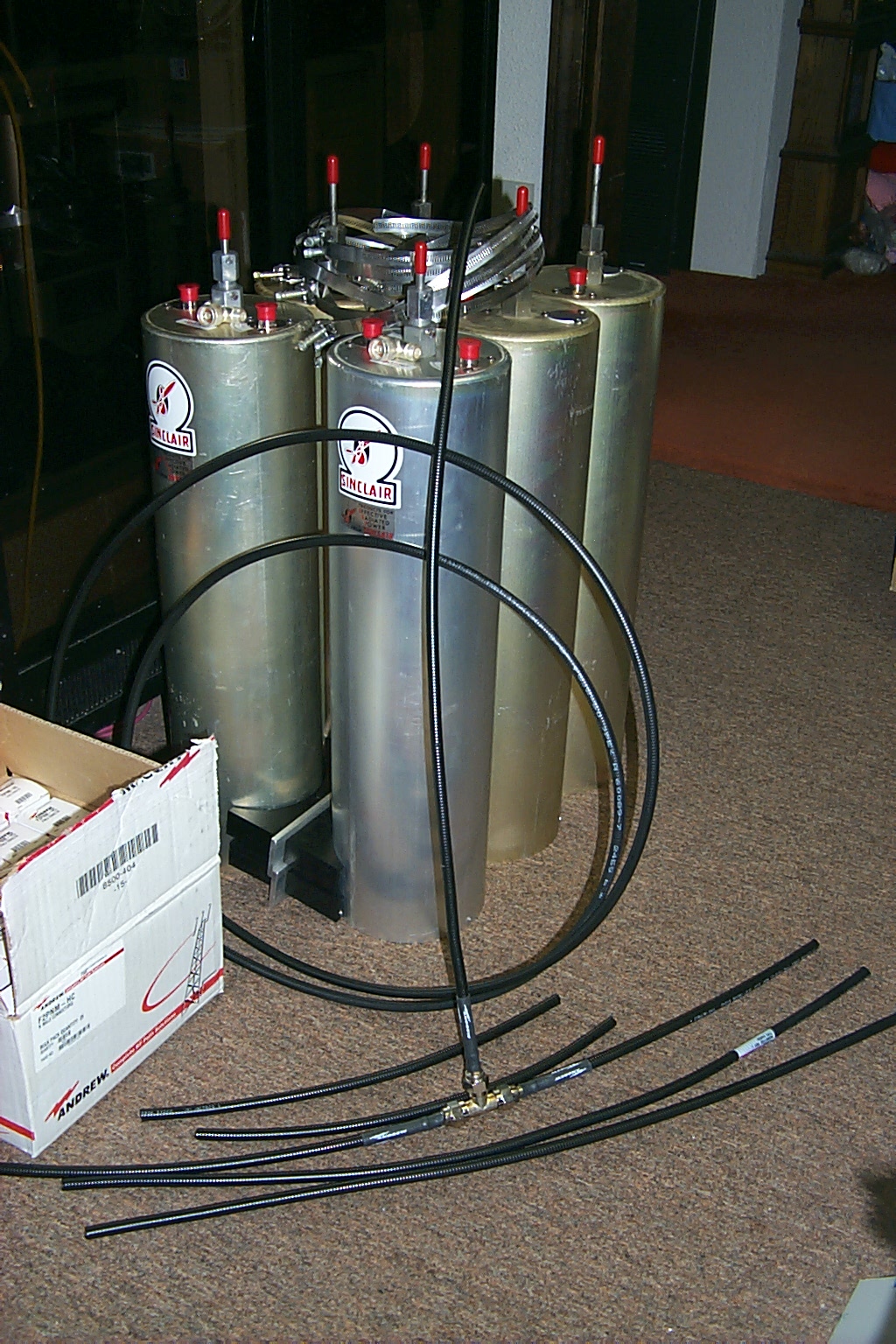
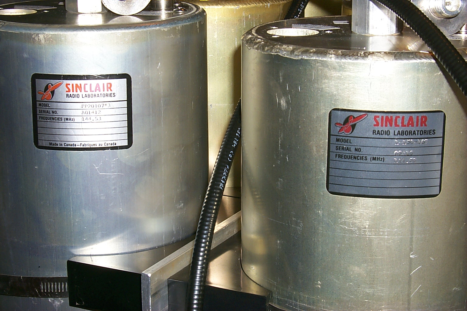
April 2011 - Vacation Fun
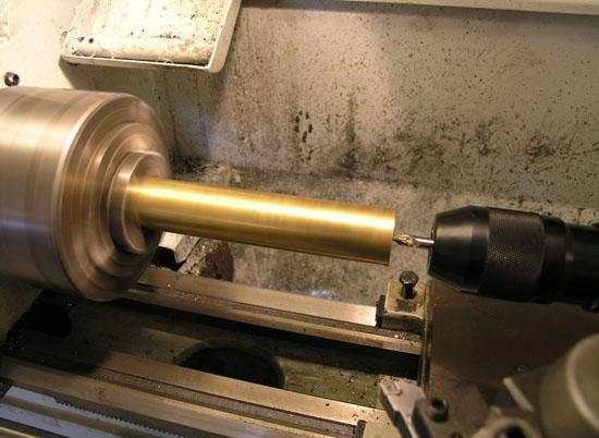
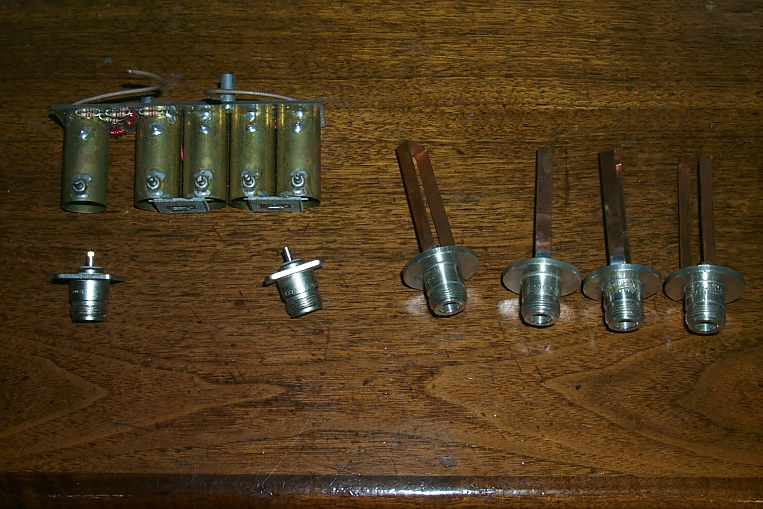
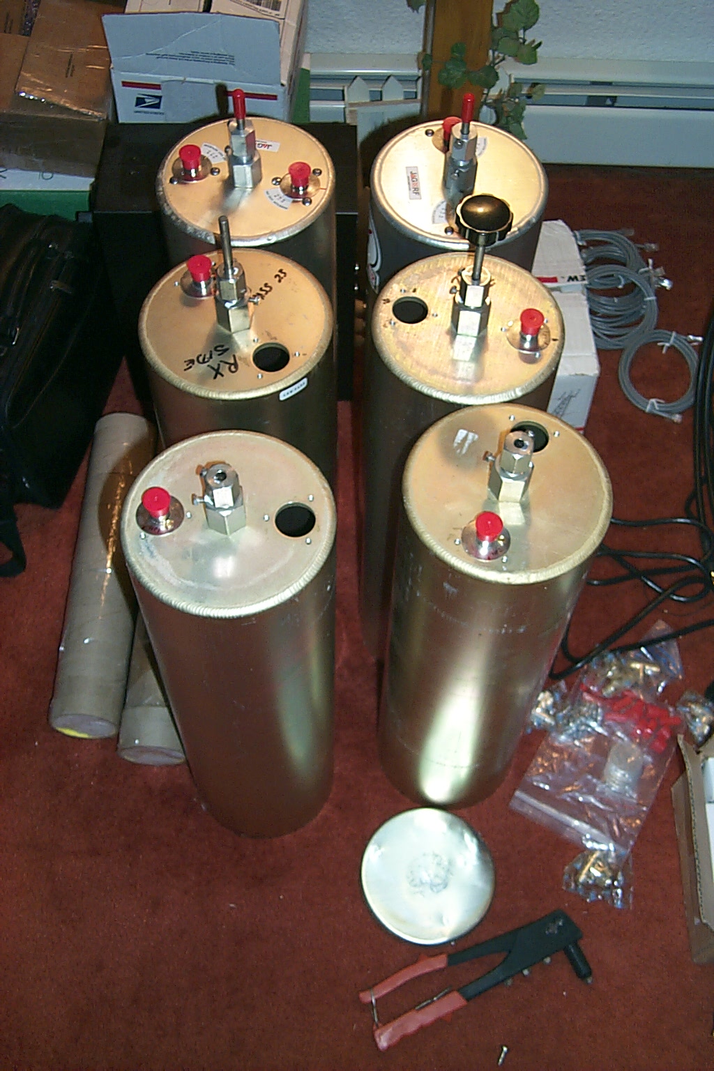
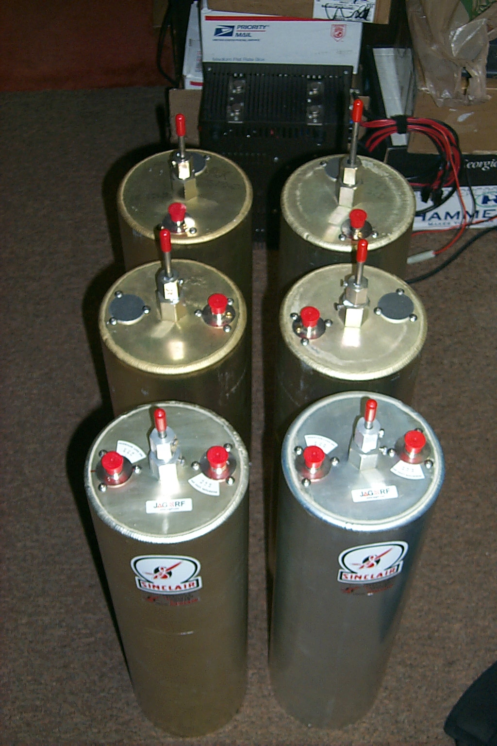
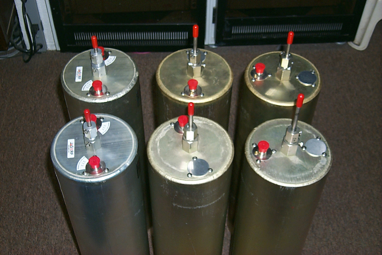
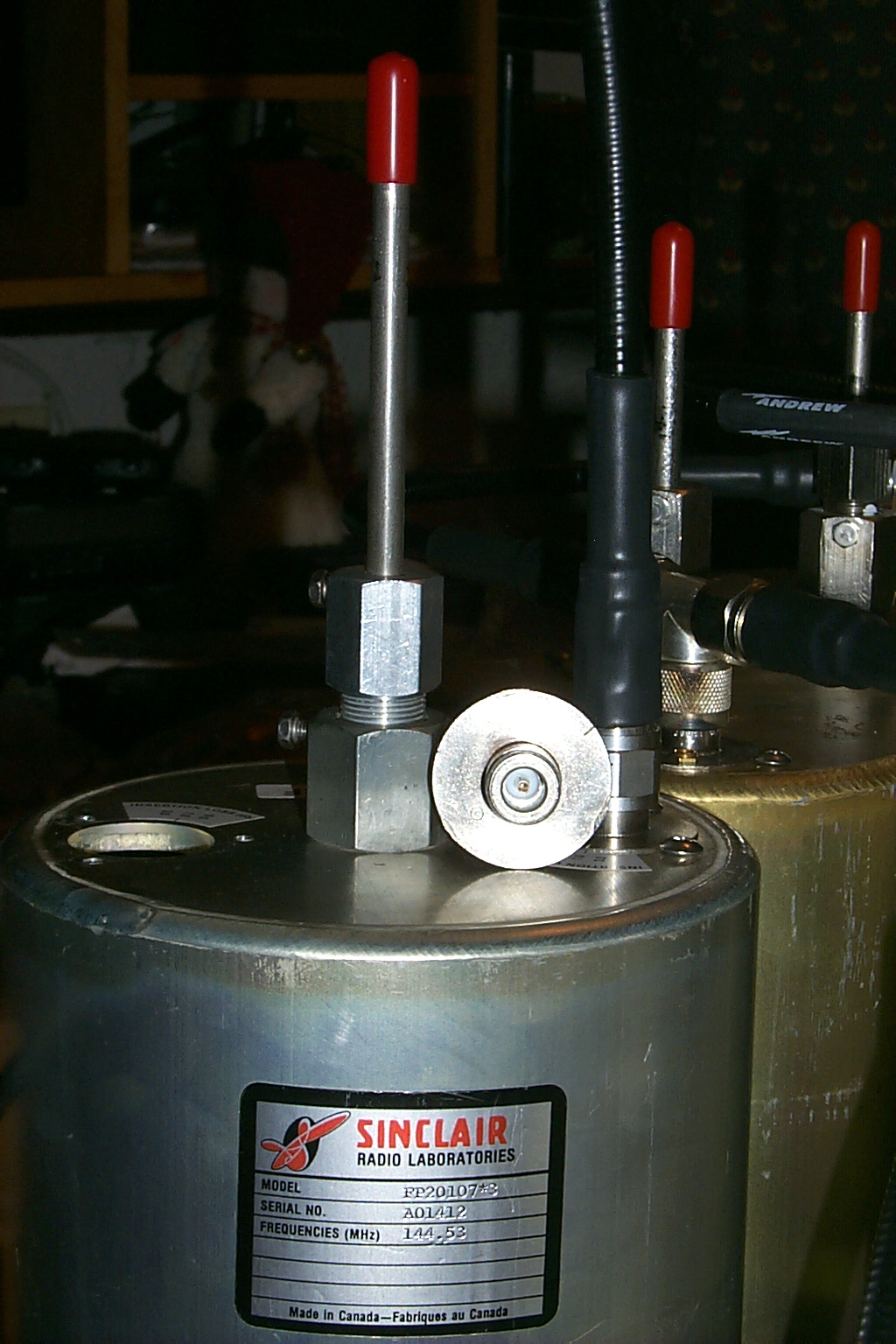
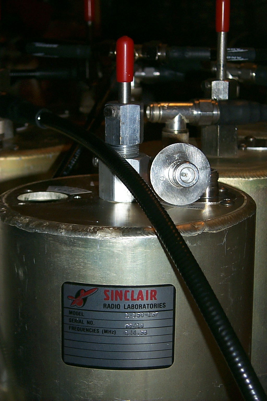
I had four Sinclair Bp/Br cavities in storage that were available however they needed some minor repair work and did not have any coupling loops. I took some measurement and contact my friend Jag in Canada to purchase some new coupling loops and a set of matching band pass cavities...
(click on images to enlarge)
I would build a new six cavity duplexer using these Sinclair filters which have a higher Q and should provide the additional isolation we needed to keep the transmitter out of the receiver with the improved sensitivity. I would also have to fabricate custom mounting bracket to secure the Sinclair cavities into the existing rack cabinet.
(click on images to enlarge)
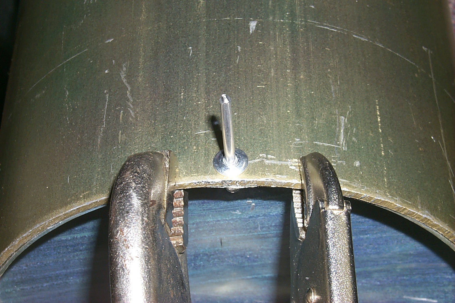
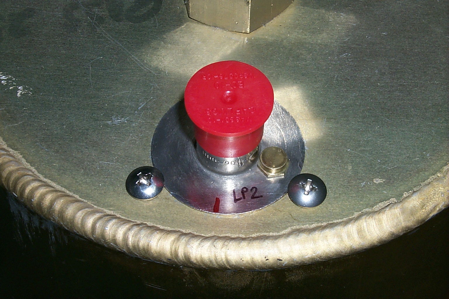
The BP/BR cavities had their tuning rods slip down inside during shipping so I had to open the bottom covers to re-install the tuning rods. Then I drilled holes and used pop rivets to secure the bottom covers back onto the cavities.

(click on images to enlarge)
With the new mounting brackets ready, the tuning rods all back into their correct positions, and the new coupling loops installed I turned my attention to the phasing harness. I cut all new jumpers using Andrew FSJ-2 super-flex heliax cable and went to work building the new custom phasing harness.
(click on images to enlarge)
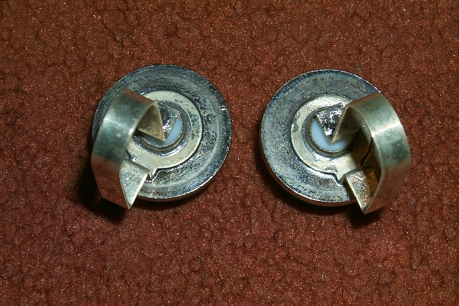
I was able to find all new Amphenol Silver
Teflon TEE connectors to build the new phasing harness.
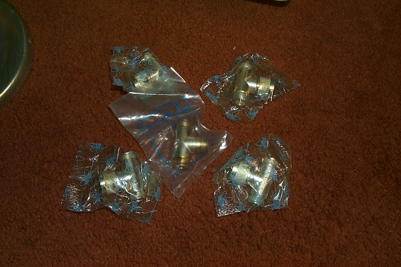
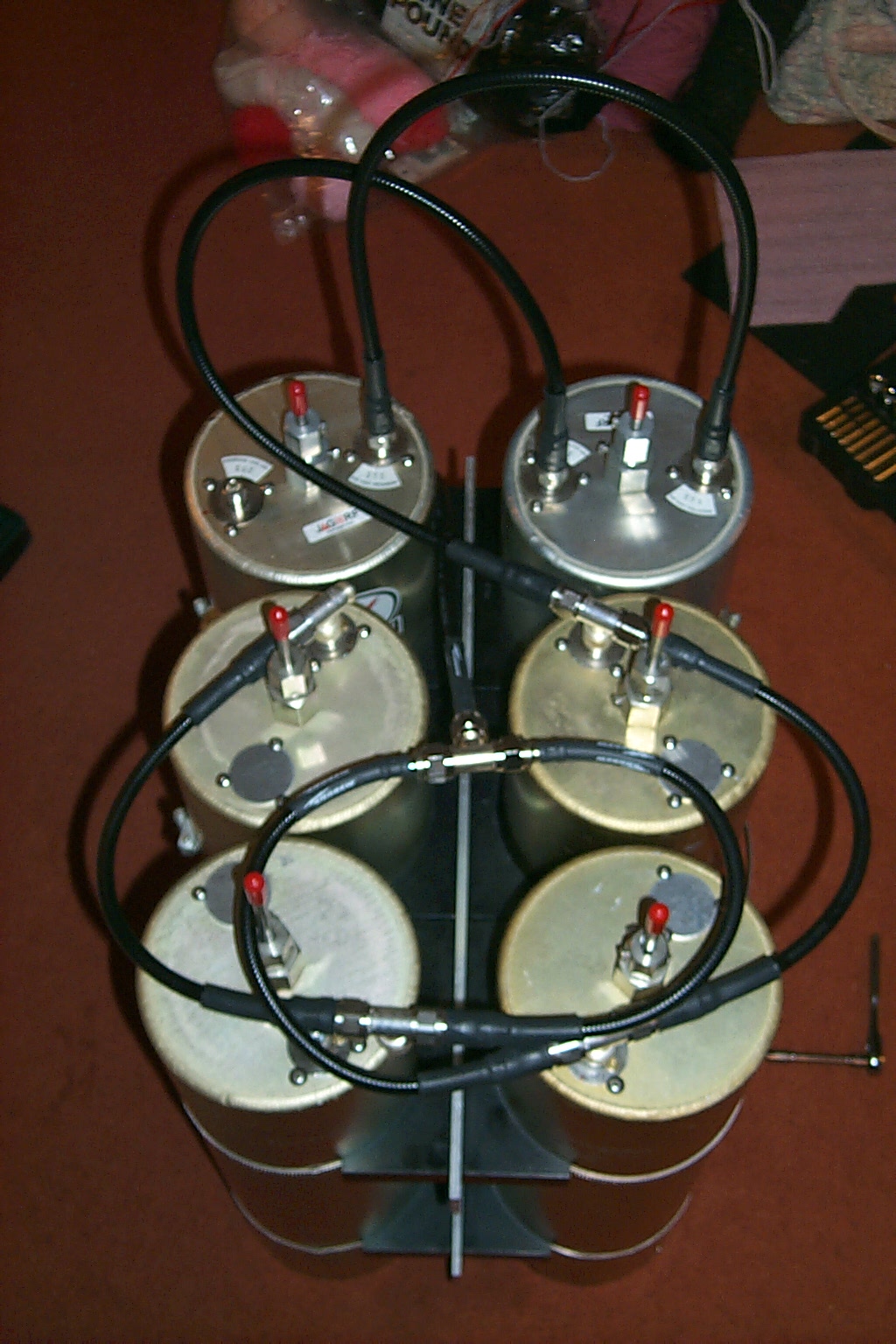
(click on images to enlarge)
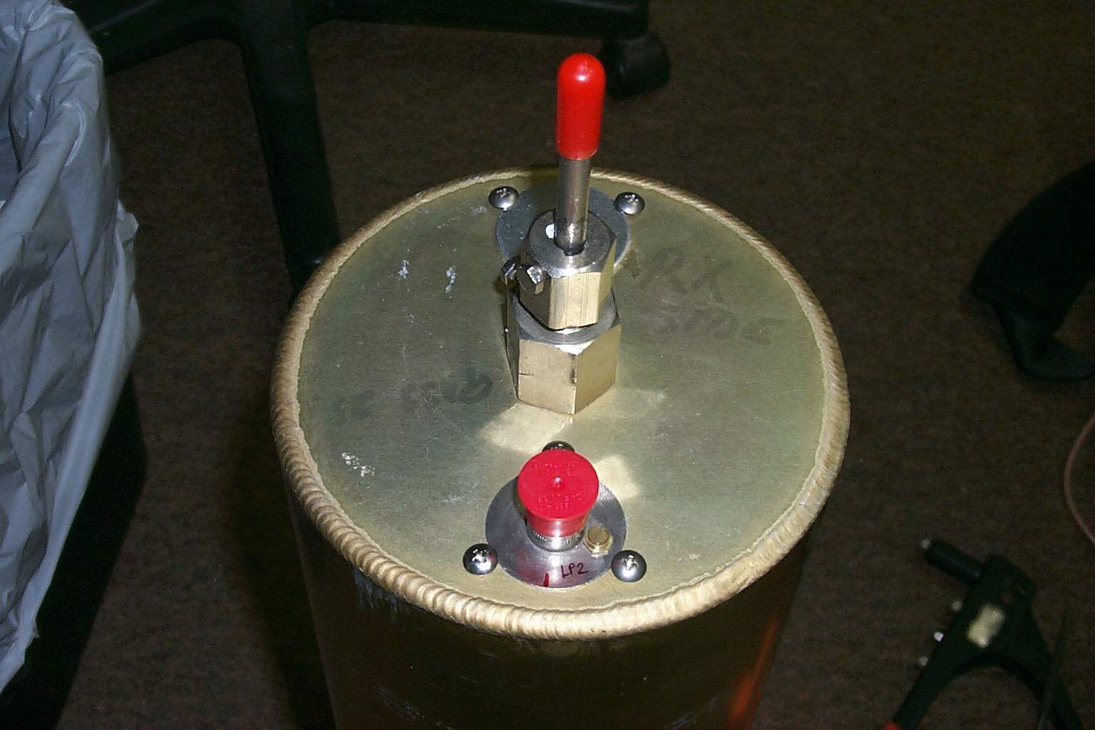
The cavities all tuned very well however there was an issue with the captive spring tension of the fingers on the stationary part of the tuning sections. When the tuning rods had fallen down inside the cavities during shipping they stretched out the fingers just enough that the movable section would drop down inside the cavities when the coarse adjustment lock nut was loosened.
(click on images to enlarge)
I would have to drill out all the new rivets and get back inside the cavities to tighten up the individual fingers inside each cavity. I used some large heat shrink tubing to evenly squeeze all the fingers closed so they would make better contact with the center tuning section.
(click on images to enlarge)
Once all the fingers in all the cavities were tightened up I re-assembled everything and completed the initial tuning of the cavities.
(click on images to enlarge)
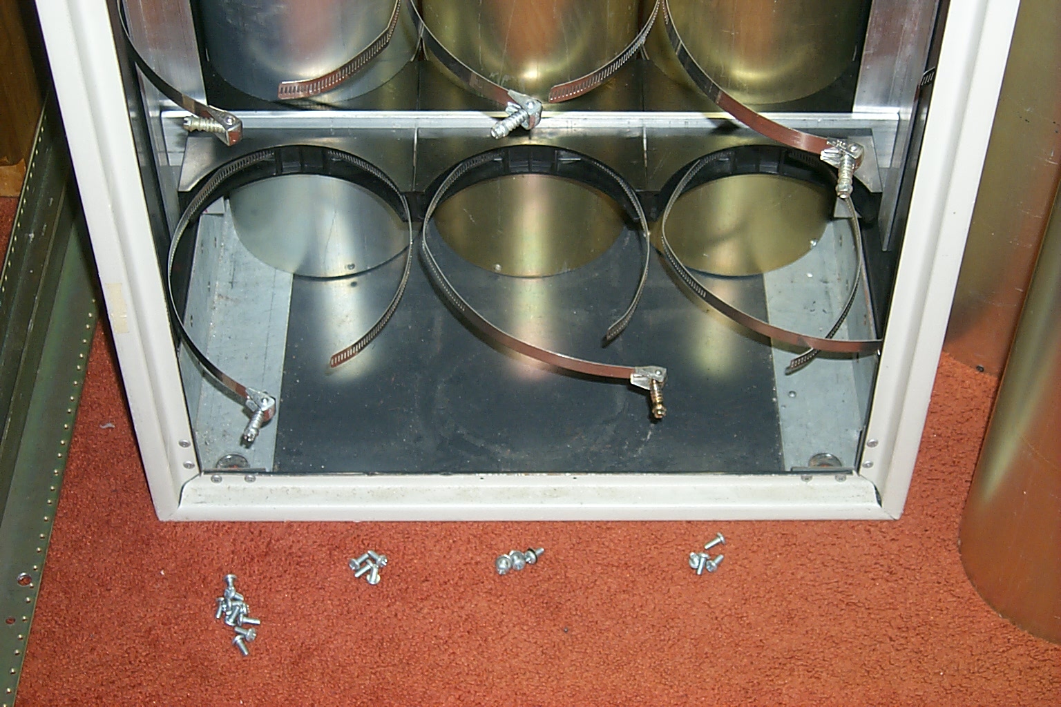
Once I removed the smaller Wacom duplexer from the rack cabinet it was a challenge to squeeze the much larger Sinclair cavities into the same location. There was just barely enough room in the bottom of the rack cabinet for the new duplexer and unfortunately no way to get the unit into the rack in once piece. I ended up taking the Sinclair cavities out of the mounting brackets and rebuilding the duplexer inside the rack one cavity at a time.
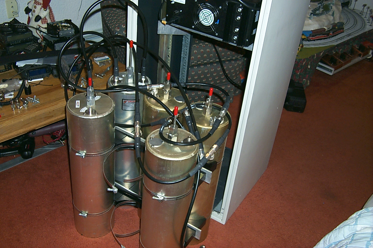
(click on images to enlarge)
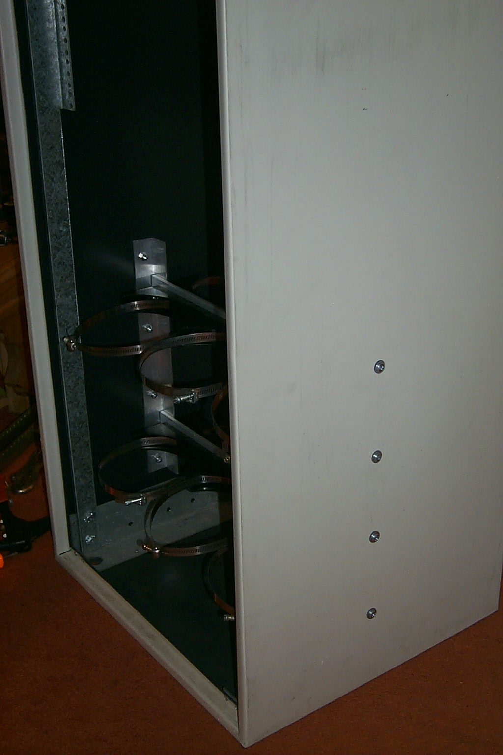
The mounting rails in the Motorola cabinet were too narrow for the six Sinclair cavities so I had to cut away a large section on the standard mounting rail to make room to squeeze the cavities into the bottom of the cabinet and them make a new set of custom mounts to secure the new duplexer.
(click on images to enlarge)
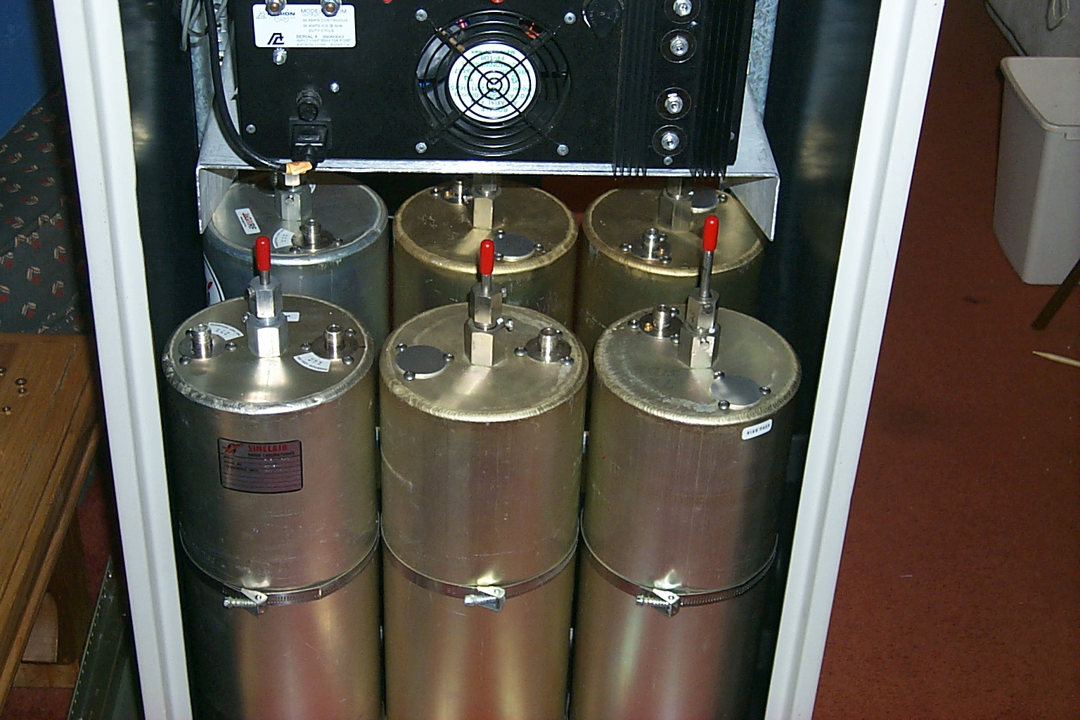
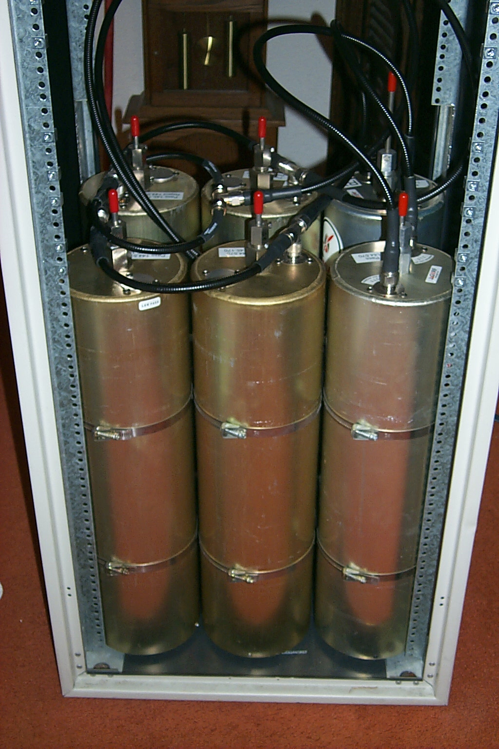
Once I had fabricated the new mounting rails for the Sinclair cavities I reassembled the new duplexer in the bottom of the rack cabinet and made sure everything fit correctly.
(click on images to enlarge)
May 2011 - Time to go see Roland... "Again"
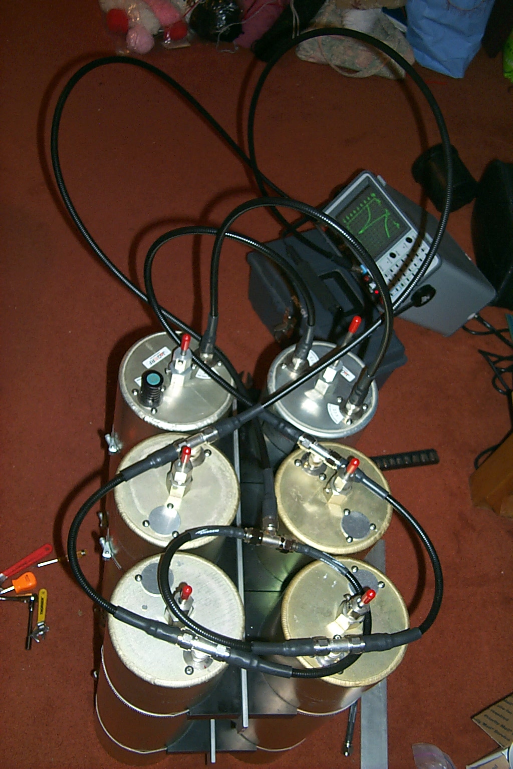
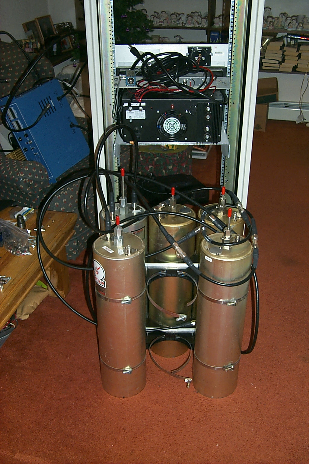
With the duplexer tuned up and mounted in the rack cabinet I was ready for a road trip to visit Roland for a super tuning session in the HAMCOW!
(click on images to enlarge)
By now the process is a familiar one... I drag a pile of cavities out to the HAMCOW, then Roland and I spend a few hours telling jokes, making fun of each other and our mutual friend, wives, and politicians while we dial in the cavities for that Super Super HAMCOW effect.
!!! Sparks - BIG BIG - Sparks !!!
Once the cavities were all set there was one tuning rod that extended to high in the rack to fit into the available space so Roland broke out the high speed cutting wheel on his grinder and removed the excess rod...
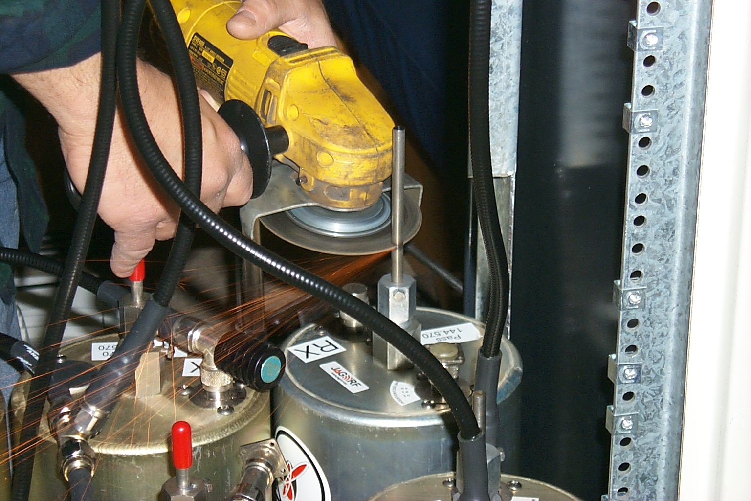
(click on images to enlarge)
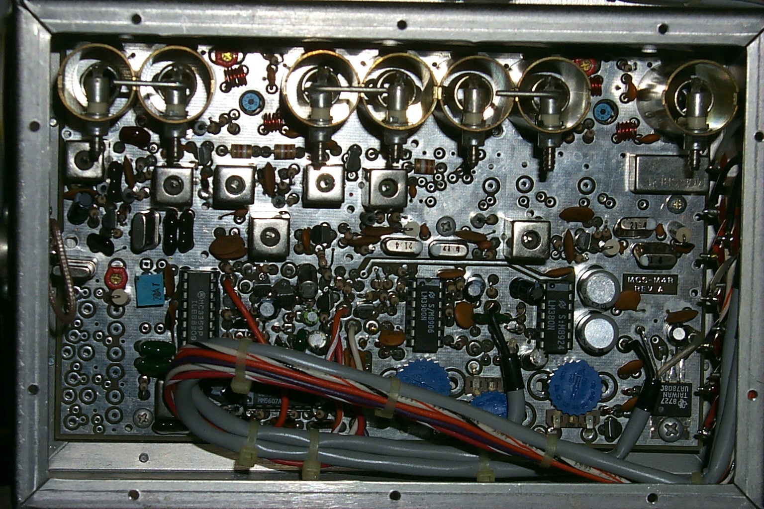
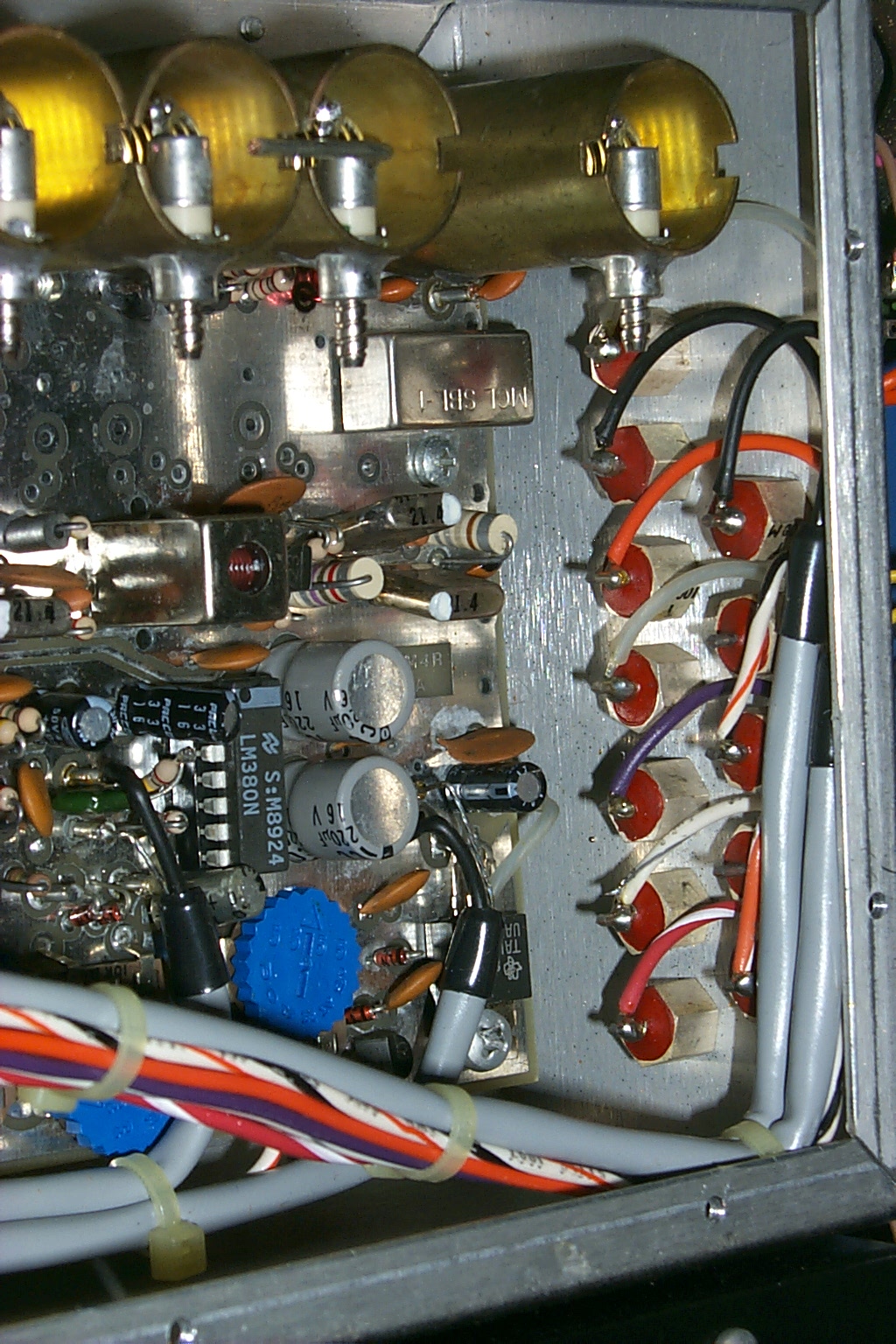
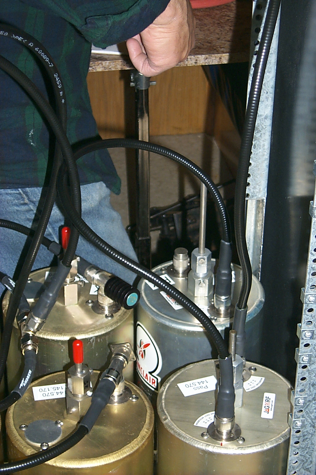
With the new cavities all tuned up I mounted all the hardware back in the rack and dragged everything back to the site. Unfortunately the intermittent issues with the receiver sensitivity, even with the improved isolation that the new duplexer provided, caused the receiver performance to be poor. I removed the Kendecom TR/RX deck and drove it up to Gary at ACS in Groveland for repairs.
Saturday September 24th 2011
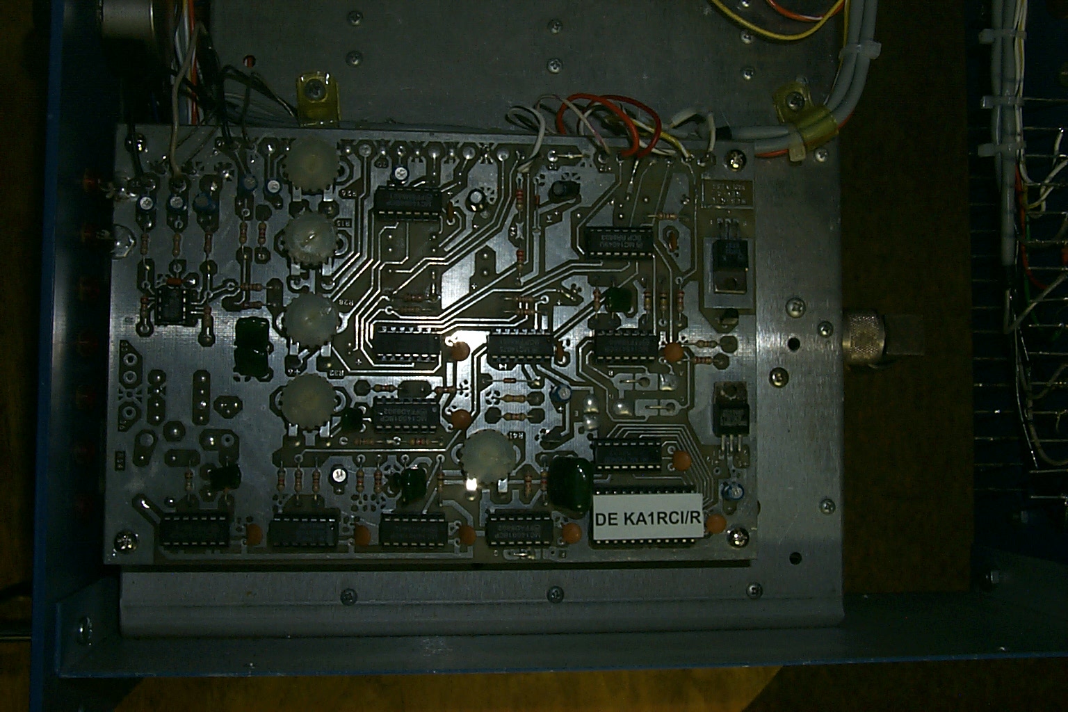
The guys at ACS in Groveland went through the Kendecom hardware end to end, replaced several parts in the receiver, re-aliened the front end, tuned up the transmitter, removed all the modification that had been made over the years, and installed a few upgrades to bring the repeater in line with the current models.
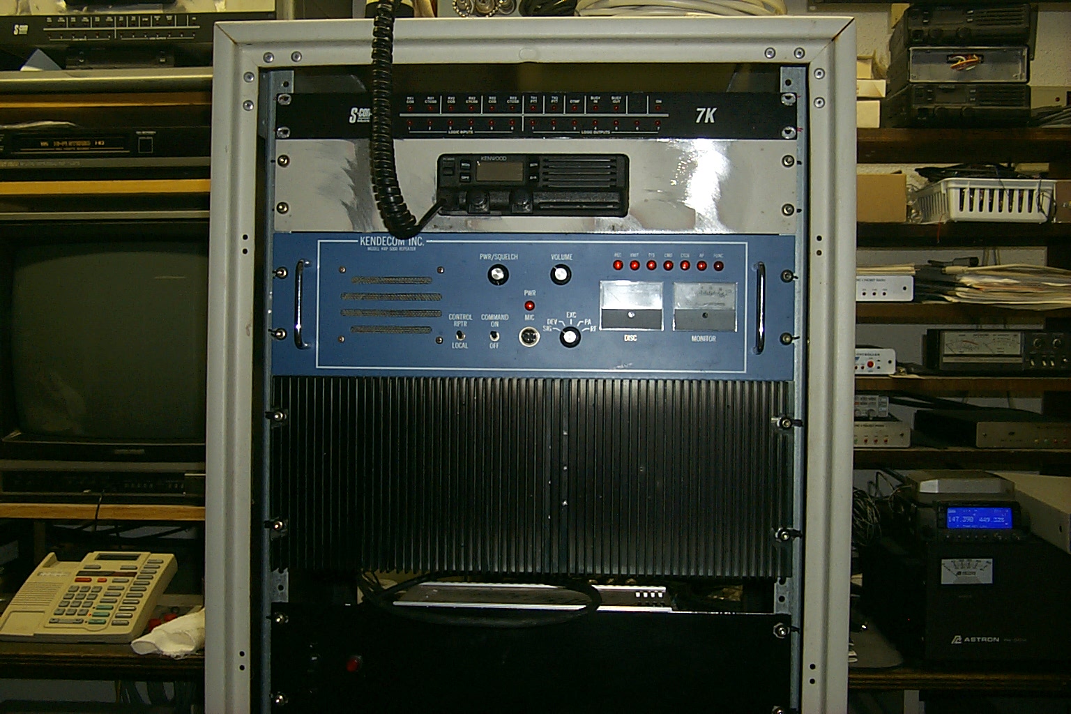
Now the basic Kendecom COS board also works with the CTCSS board, there are new switches to enable/disable the CTCSS mode, and to turn the transmitter on and off. They also updated the connections on the back of the cabinet for the external S-Com 7k controller...
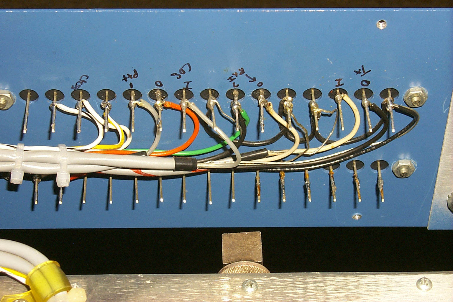
(click on images to enlarge)
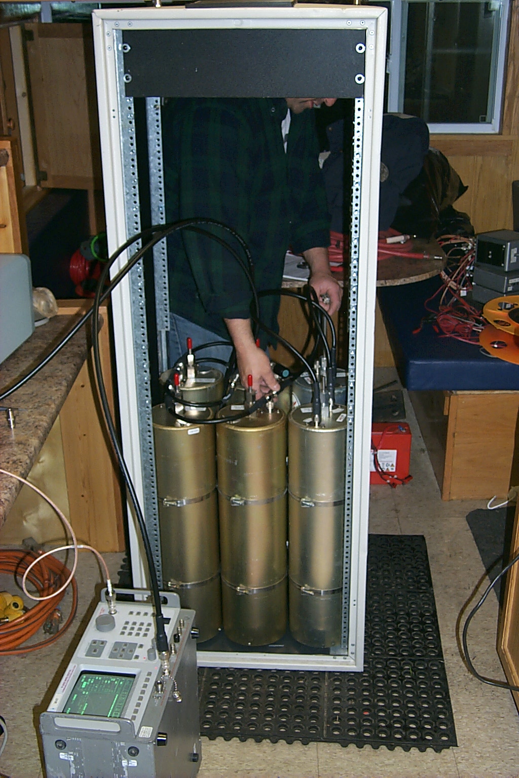
After picking up the repeater in Groveland early Saturday morning I tested everything on the bench at my house, wired up the custom cables for the external controller, and dragged everything back to the site. It took a few hours to re-assemble all the hardware back in the rack and make sure everything was working correctly.
(click on images to enlarge)
In this (hopefully final) configuration everything is working great. The repaired receiver is working very well and with the new duplexer there is no desense that I can measure or hear.
(click on images to enlarge)
With any luck this new iteration of the repeater will last another 25 years!
R. I. P. - KA1JNP /SK
Update - Saturday March 3rd 2012
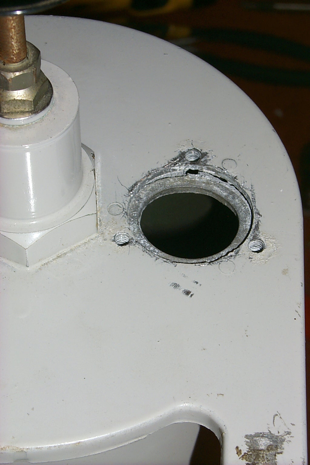
The Lincoln repeater has been acting up with intermittent issues of very poor receiver performance. Distant stations that had been able to use the repeater with low power can no longer even hear it. After a quick visit to the site I was able to confirm there was a problem with the antenna as the VSWR was off the scale... (not good)
Update - Thursday March 22nd 2012
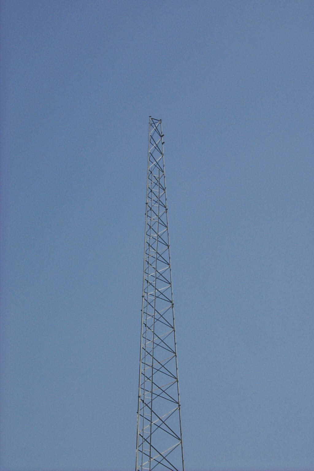
Dave W2DAN was able to swing by the site with me and swept the hard-line with his Anritsu site master confirming that the primary VHF repeater antenna was disconnected... The distance to fault test show an open connection at 162 feet up at the top of the tower... (very not good)
Update - Monday April 9th 2012
Apparently back in late February there was some work done on the tower that damaged the hard-line connections and took the repeater off the air for a few months while I saved up the funds to have my tower crew make the necessary repairs.
We spent several
hours are the site installing new connectors and securing the hard-line to the
tower successfully getting
the repeater back on the air this weekend.
The Lincoln 145.170 repeater is back on the air and working great once again. Special thanks go out to Judson W1JMZ and Bob W1YRC for all their help getting the repeater back on the air...
Update - Saturday December 5th 2015
After enjoying many years of service at the commercial site in Lincoln, RI the site was sold and the new landlord asked me to vacate the site and remove my antennas from the tower. After all the hard work spent on rebuilding the hardware and getting that site online with great coverage in the northern part of the state I was really disappointed. I contracted with a tower crew and had the antennas removed, it was a very sad day�
(click on images to enlarge)
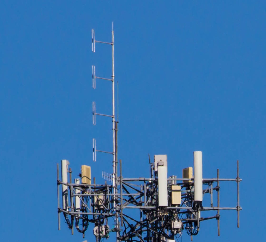
Not too long after removing the repeater hardware from the Lincoln site I was able to secure a new site just 2 miles away and started saving up my spare change to fund the tower crew to install my JAG RG Exposed Dipole Array on the new tower. Six months later I was able to save up enough to have my antenna deployed at the new site and the same tower crew that took the antennas down at the Lincoln site put them back up at the new site in Cumberland.
(click on images to enlarge)
Then I spend 13 hours on Thanksgiving day, Thursday November 26th, 2015 tearing down the Legacy KA1JNP repeater hardware, moving it to the new site, and rebuilding everything in the new rack cabinet.
(click on images to enlarge)
The initial signal reports coming in so far indicate that the coverage area from the new site in Cumberland, RI is just as good as the old site in Lincoln, RI maybe even just a little bit better in a few locations.
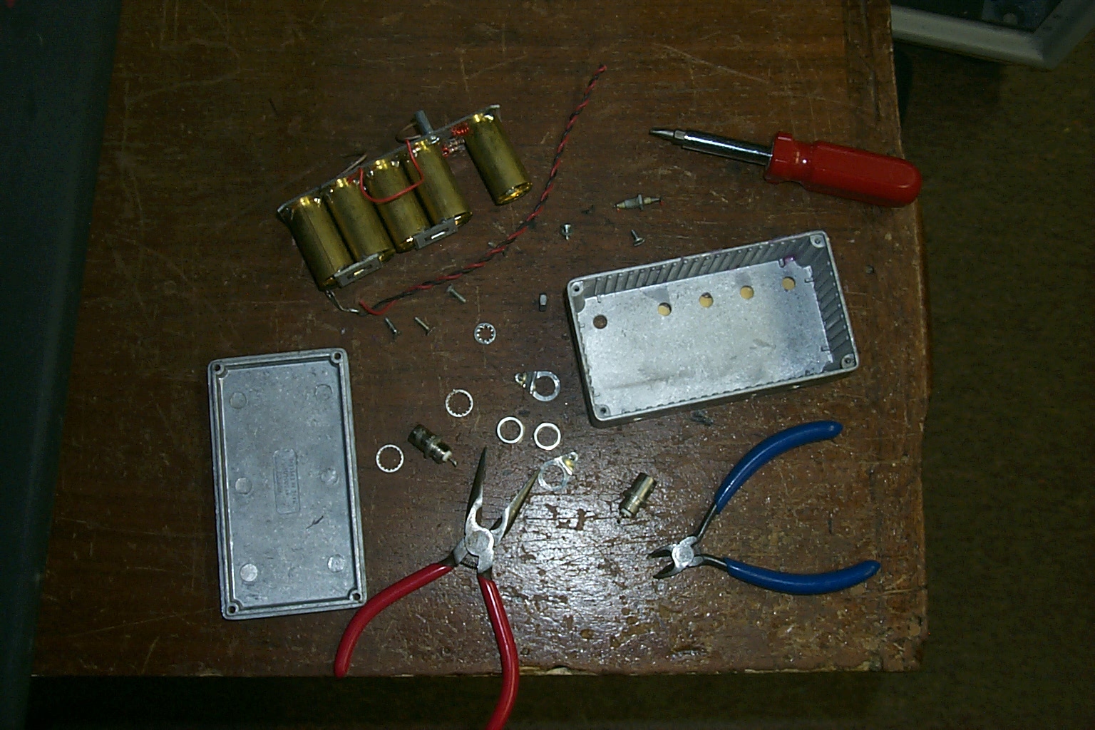
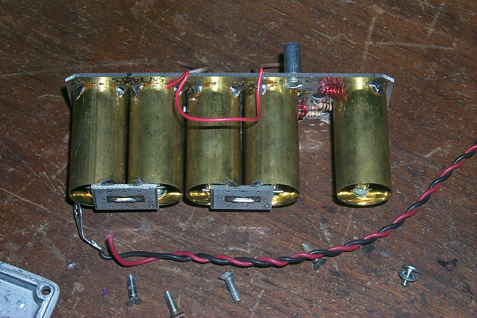
The 28-year-old KA1JNP hardware is starting to have issues, the transmitter becomes unstable when the temperature drops down below 30 degrees so I deploy a fun �low tech� 100-watt heater to help keep the repeater stable when it is really cold.
This is the heat lamp that Sandy KA1RXB uses to keep her bunnies warm in the winter, she loaned it to me to keep the 145.170 KA1JNP transmitter warm while I work on replacing the 28+ year old hardware.

(click on images to enlarge)
Work was already underway to build a new repeater with new hardware like I have already deployed in Westerly, Exeter, and Portsmouth. However I would have to wait until time and funds are both more plentiful before I would be able to replace the old Kendecom with a new Kenwood TKR-750.
January 9th 2016 - New hardware goes online...
On Thanksgiving day 2015 I had deployed the KA1JNP hardware at the Cumberland site, it was working however the repeater did not like the cold. The transmitter was acting up when the temperature dropped below 30 degrees. I noticed the power would drop off in the cold and the 20 watt Kendecom transmitter was going spurious sending out 20 little one watt signals all over the spectrum instead of one 20-watt signal on 145.170 MHz�
(NOT GOOD)
For that reason, I finally broke down replacing the Kendecom repeater with a Kenwood TKR-750. It took me a few months to save up the funds, and find the time to replace the old hardware, and while I was doing the work I decided to replace everything, building a completely new repeater in January 2016.
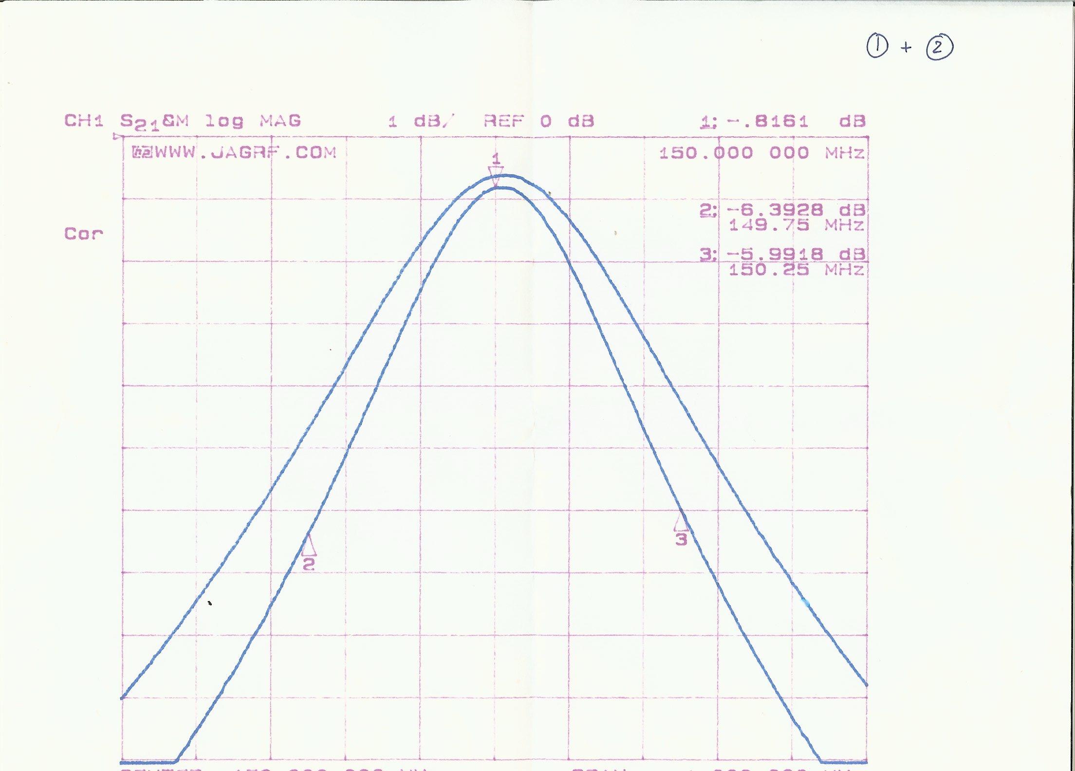
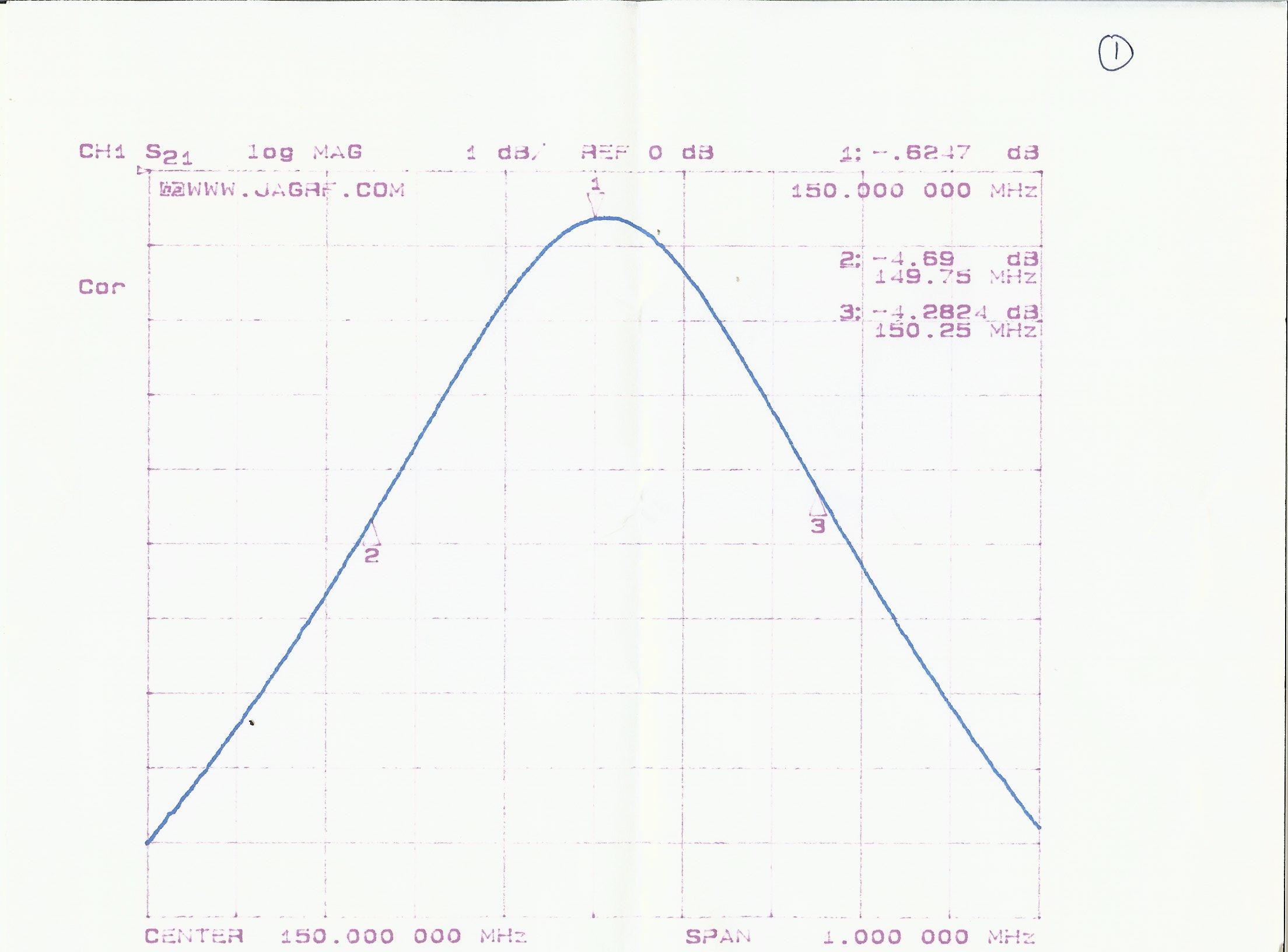
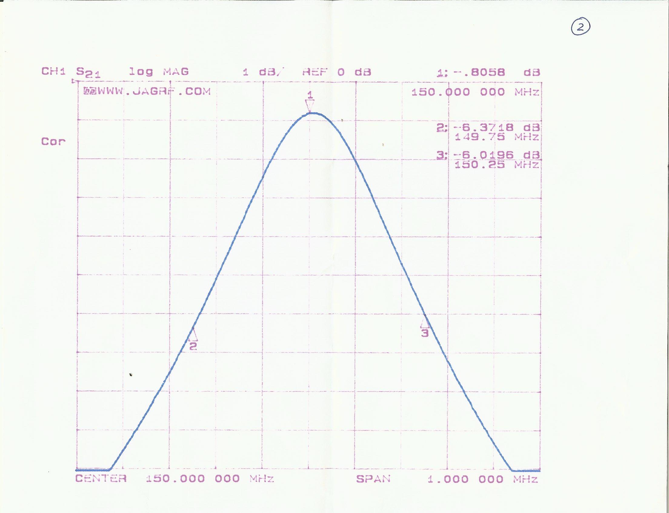
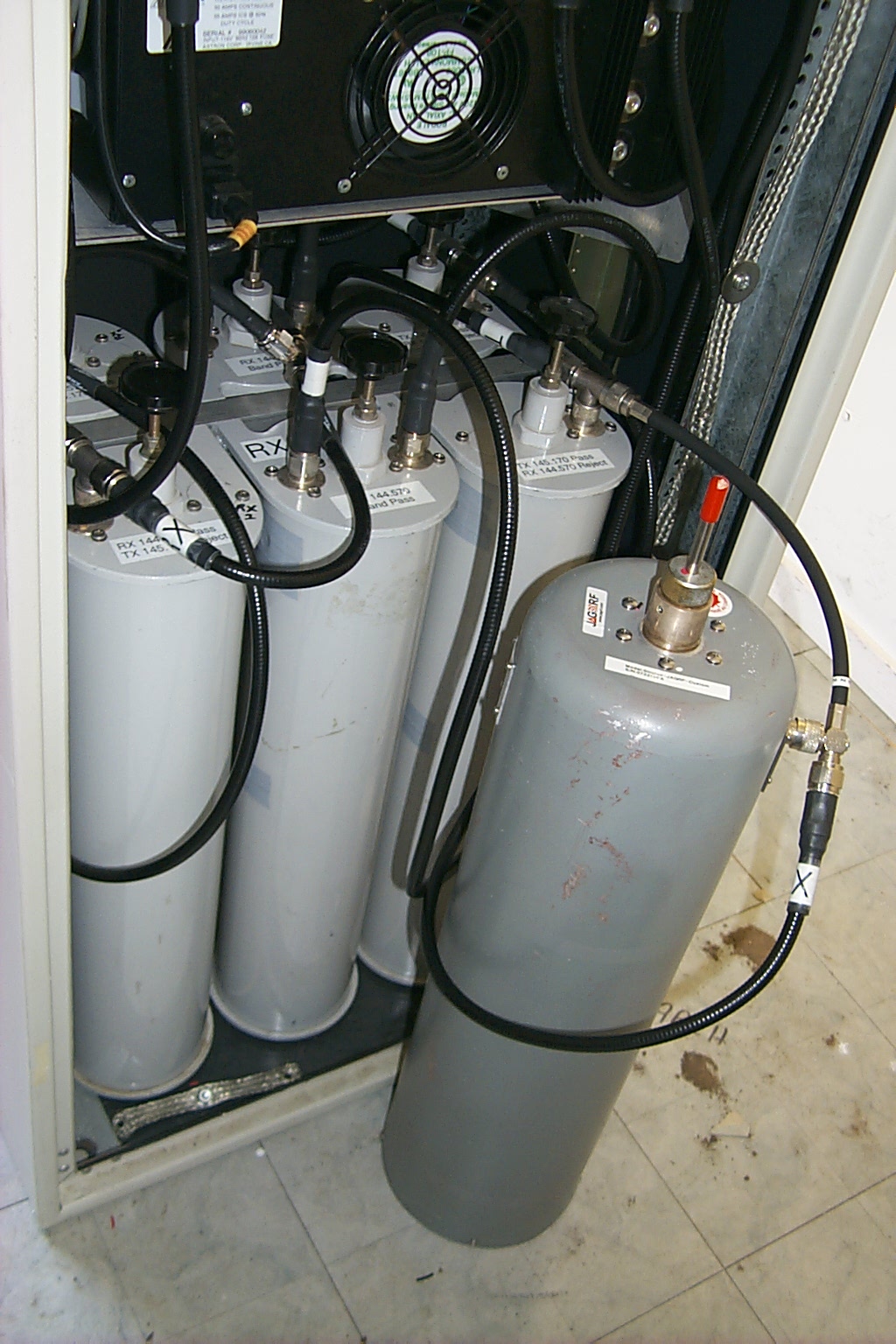
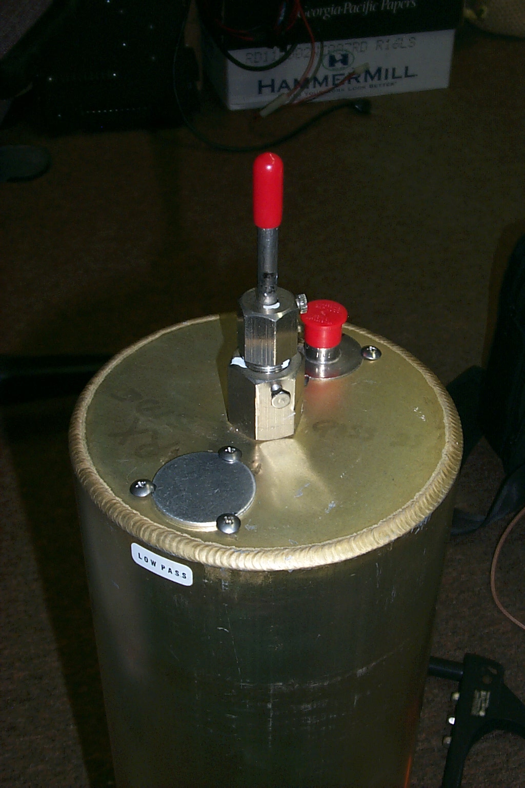
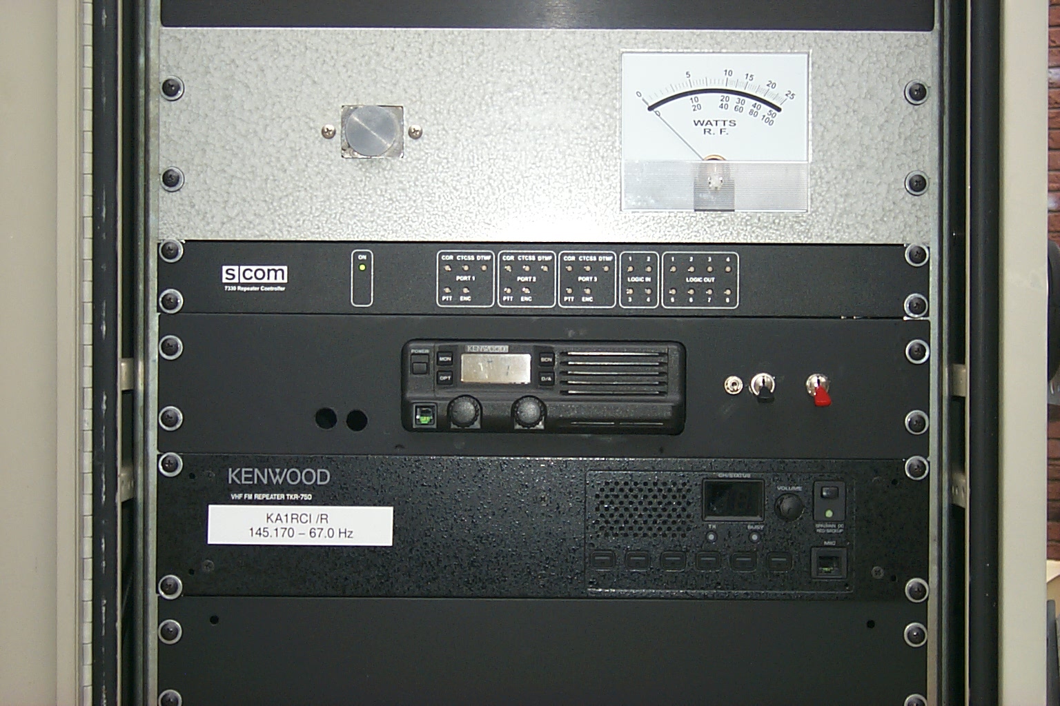
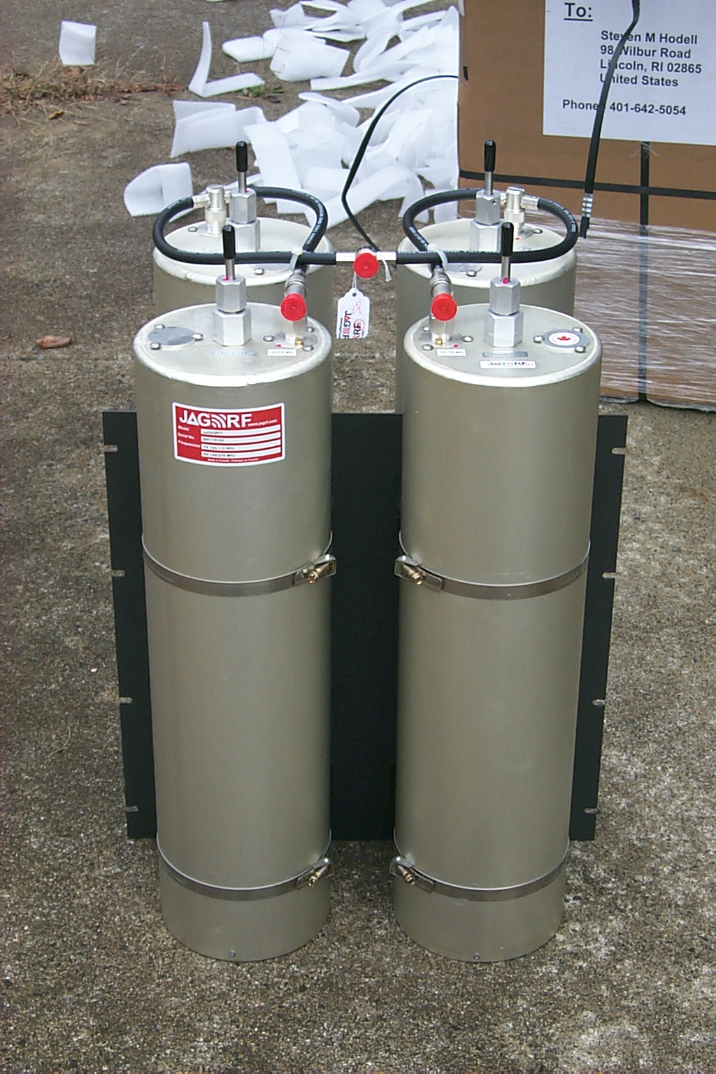
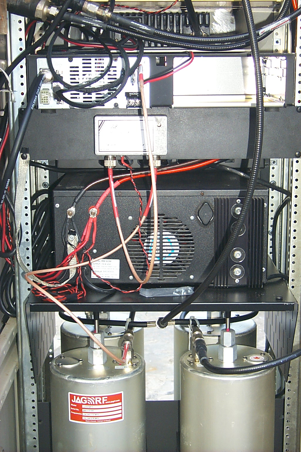
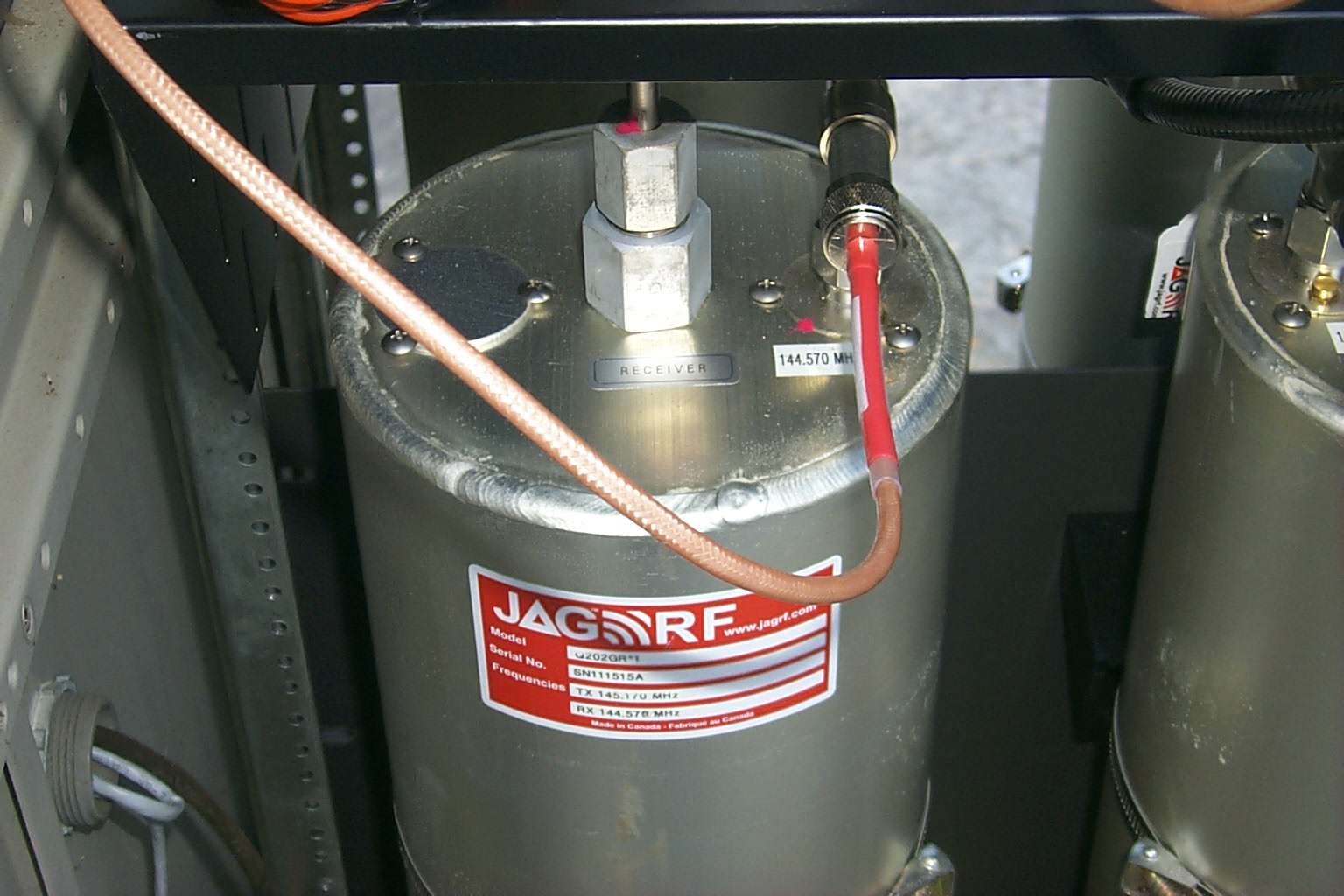
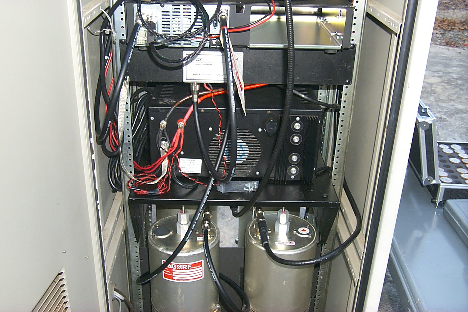
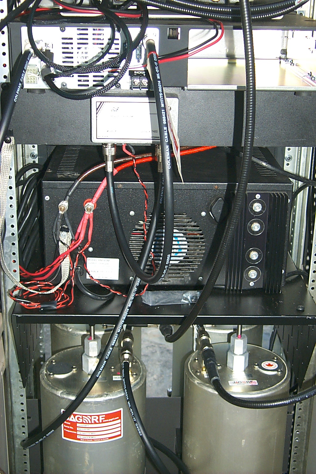
I deployed a new S-Com 7330 controller, Kenwood TKR-750 VHF repeater, Kenwood TK-830 UHF link radio, and a new JAG RF Duplexer.
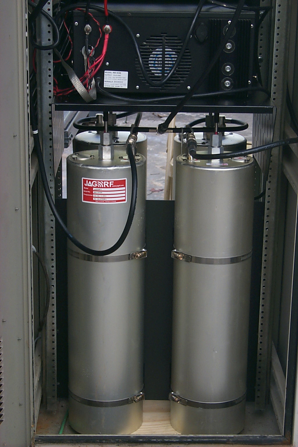
(click on images to enlarge)
I started from scratch making all new custom controller cables to interface between the 7330 controller, TKR-750 repeater, and the TK-830 link radio.
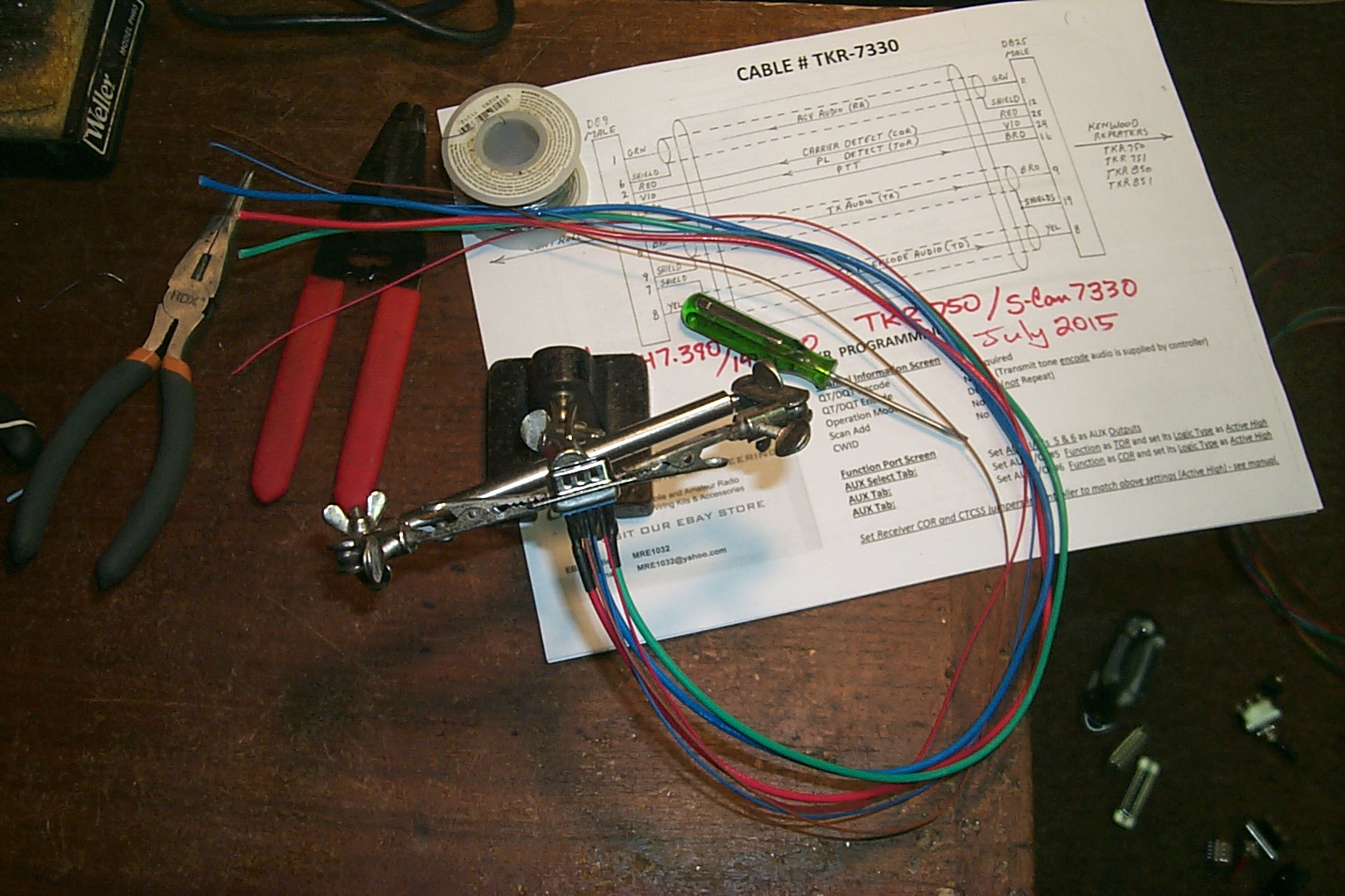
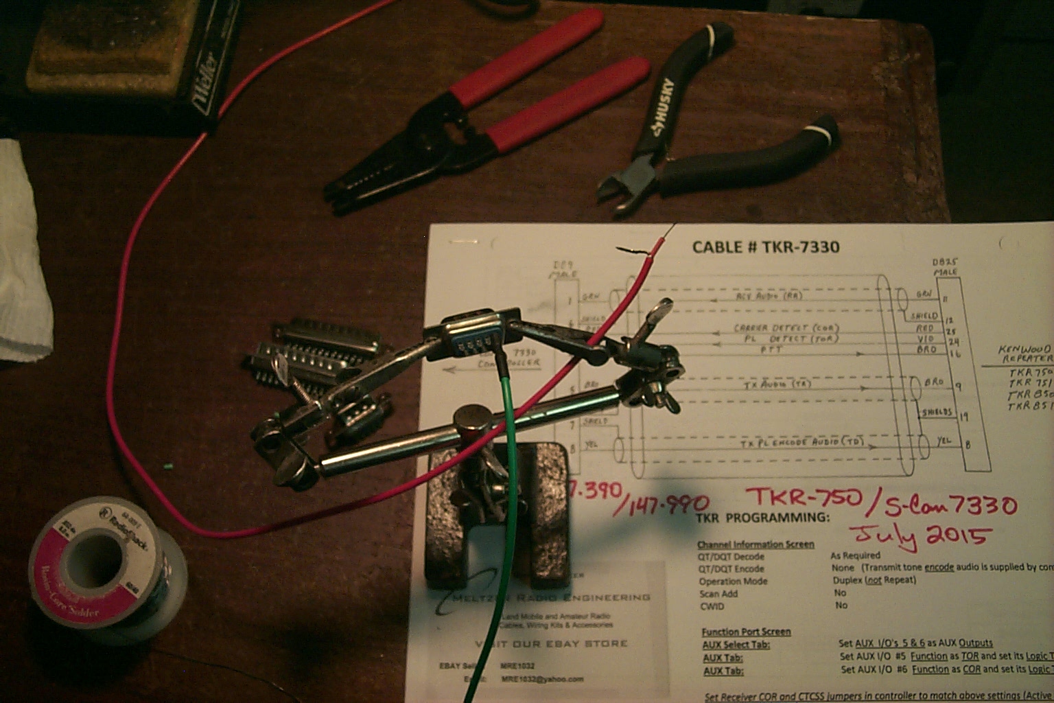
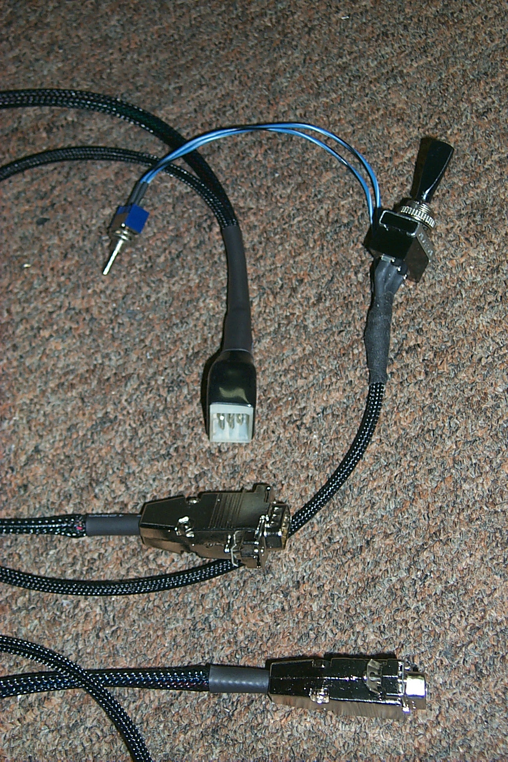
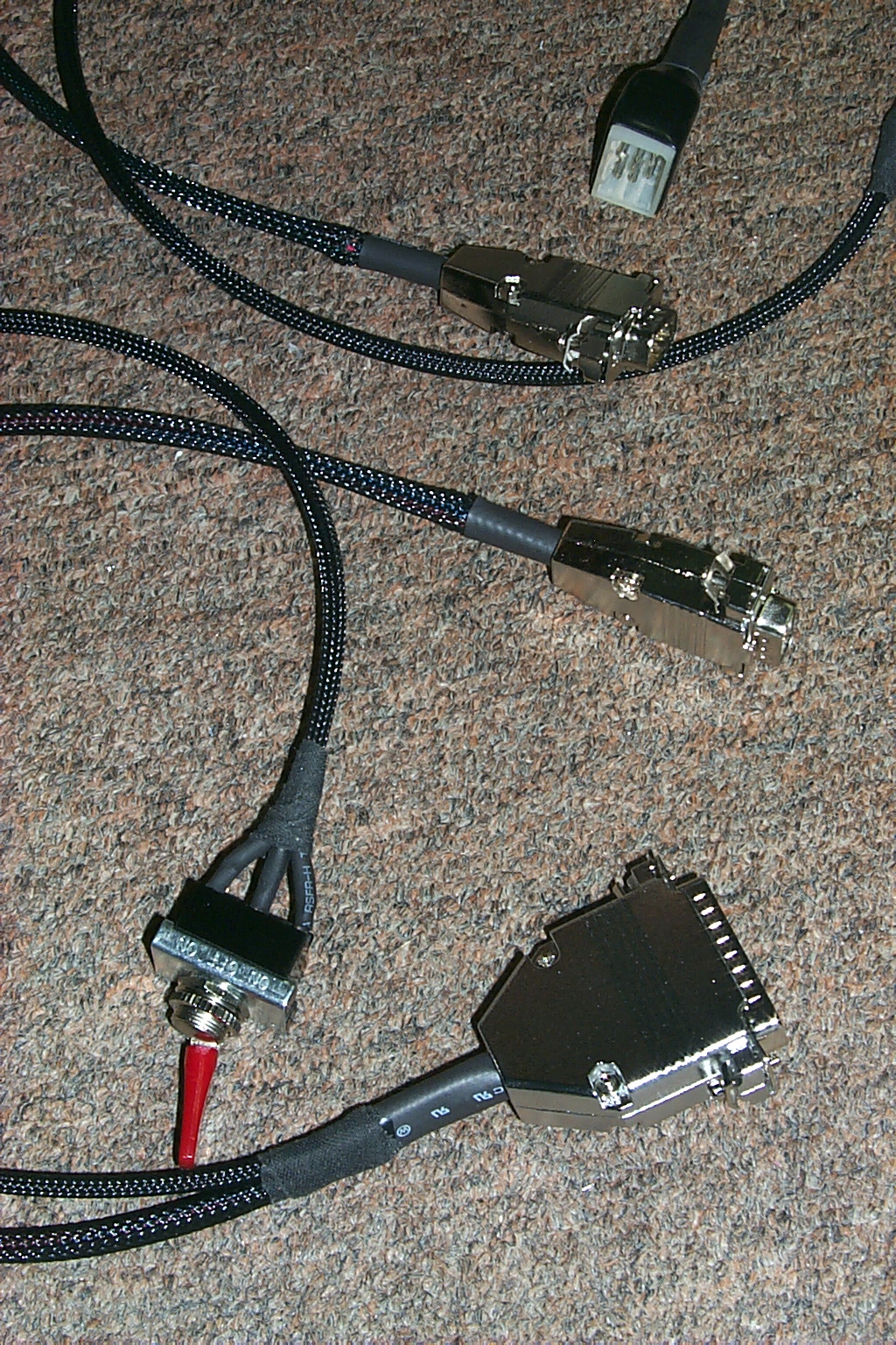
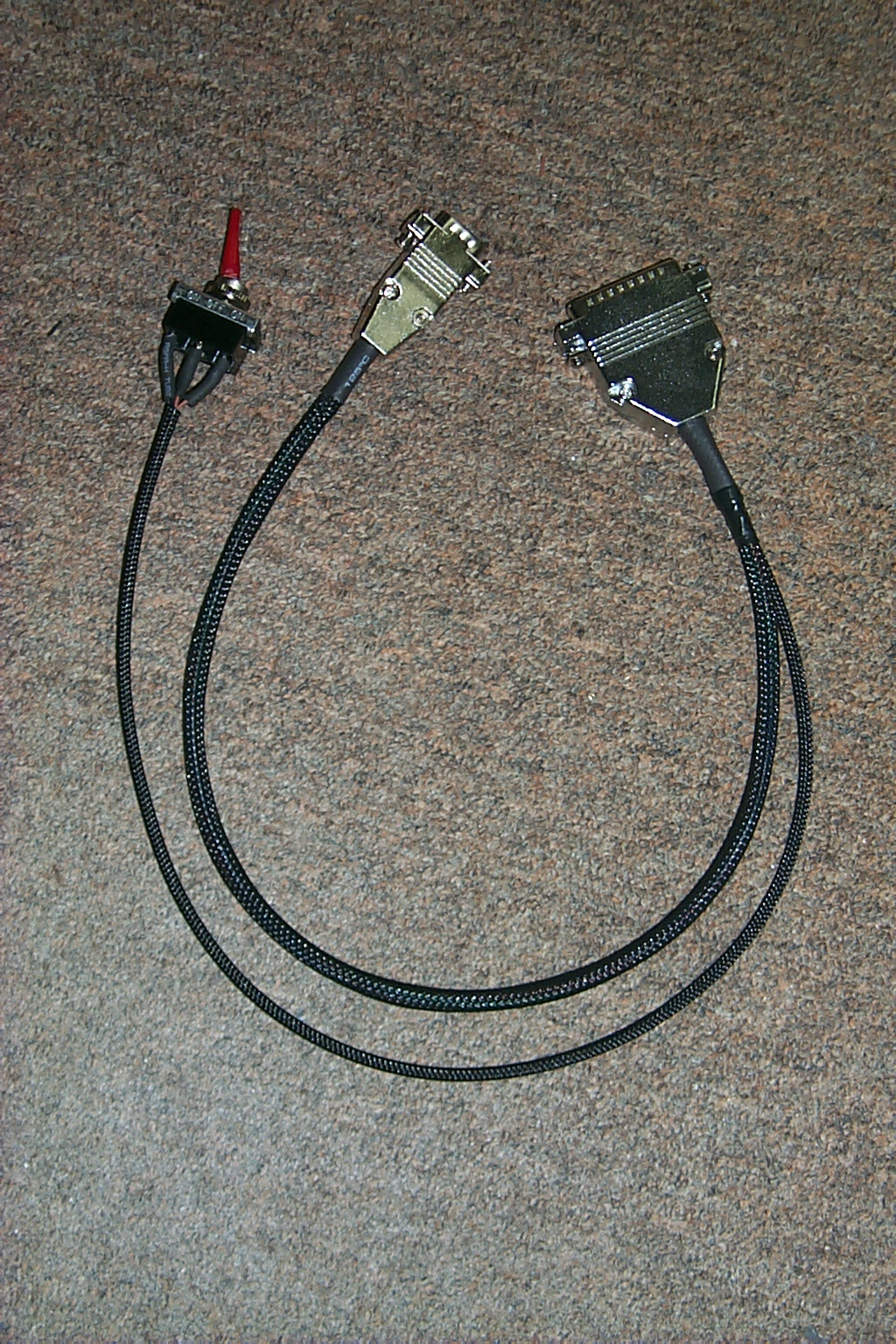
(click on images to enlarge)
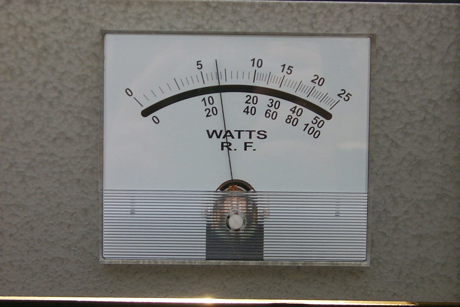
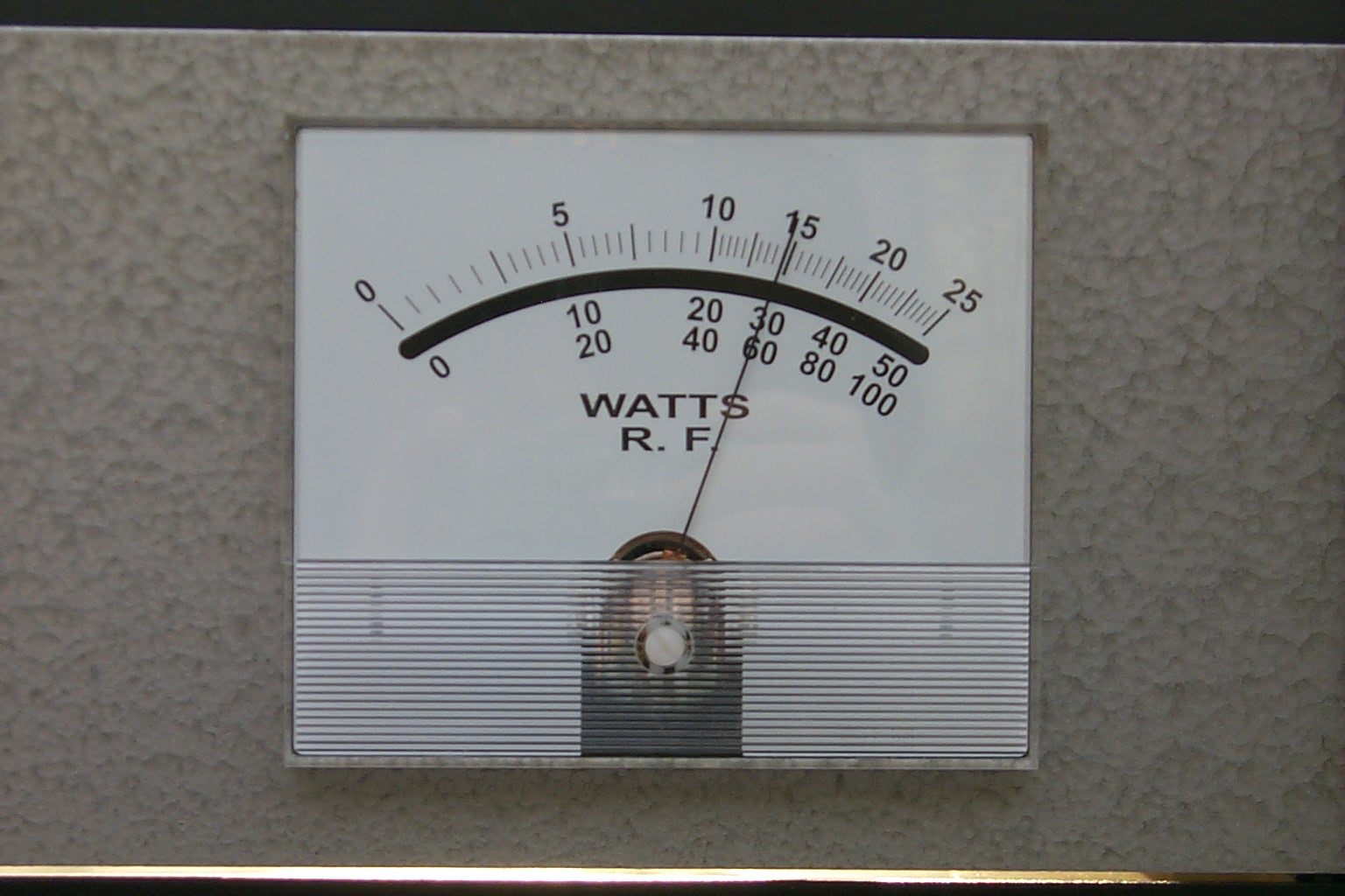
I have also repaired the 130-watt Henry PA so the new repeater is back up to full power, the Kenwood TKR-750 / Henry PA are making a very stable 58 watts out of the duplexer up to the antenna.
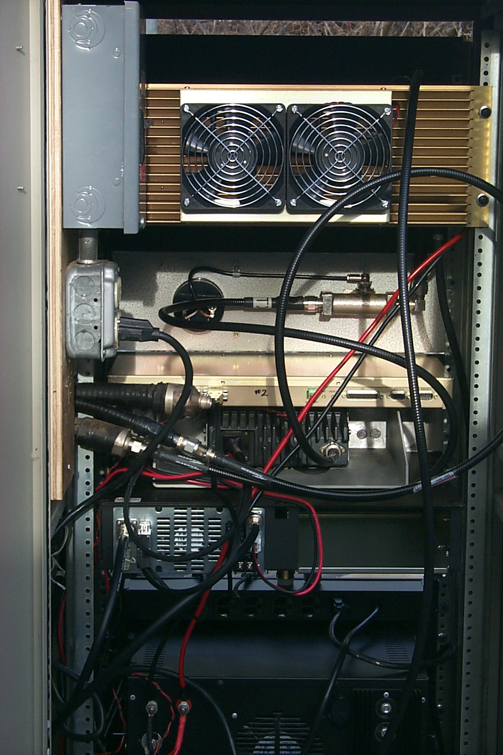
(click on images to enlarge)
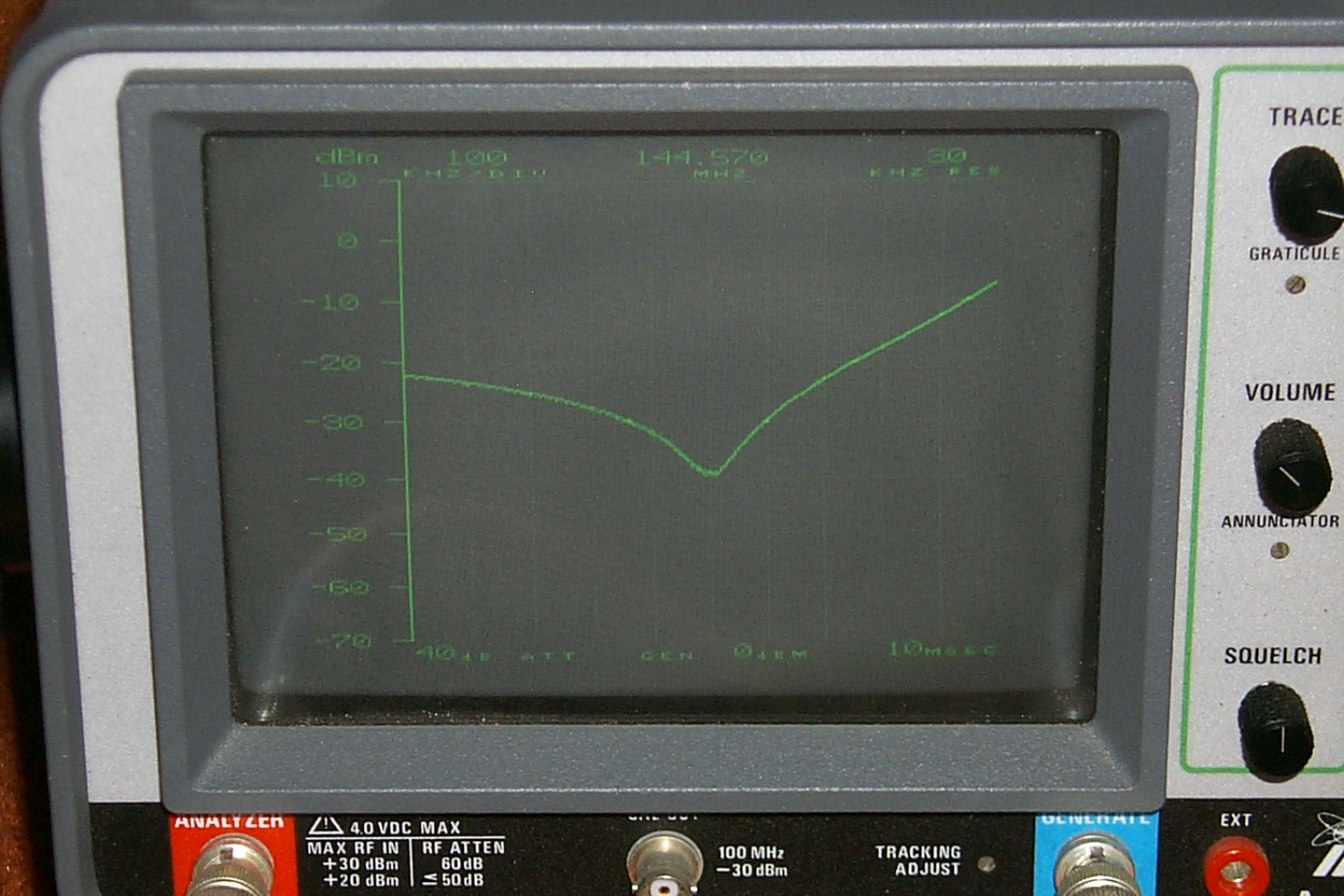
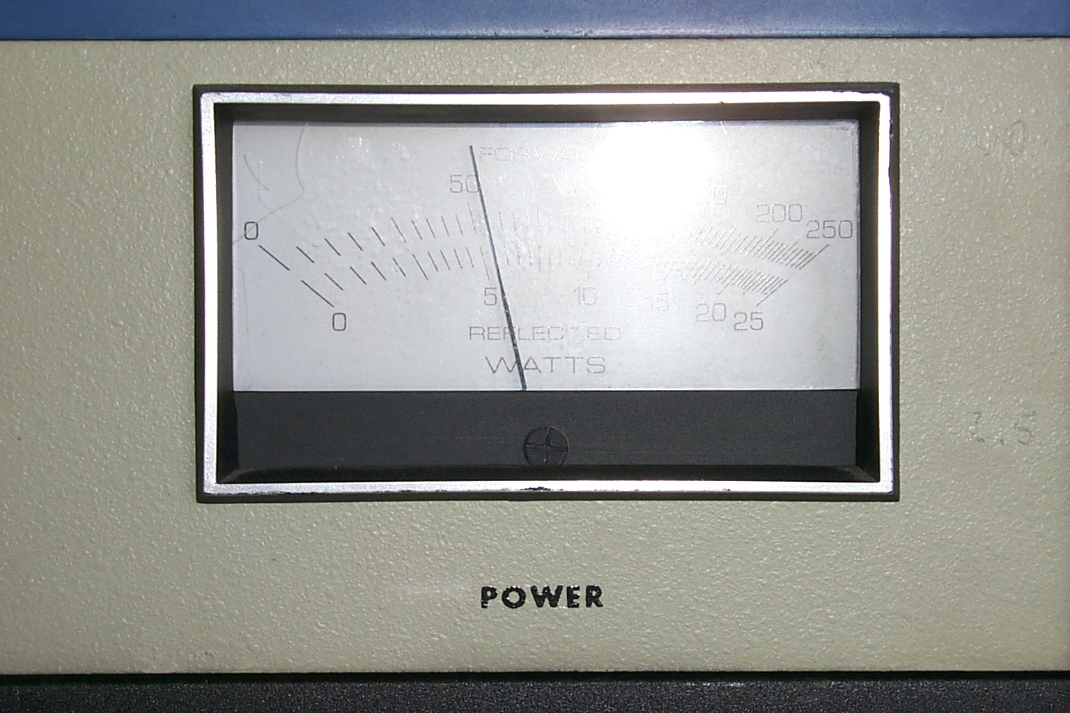
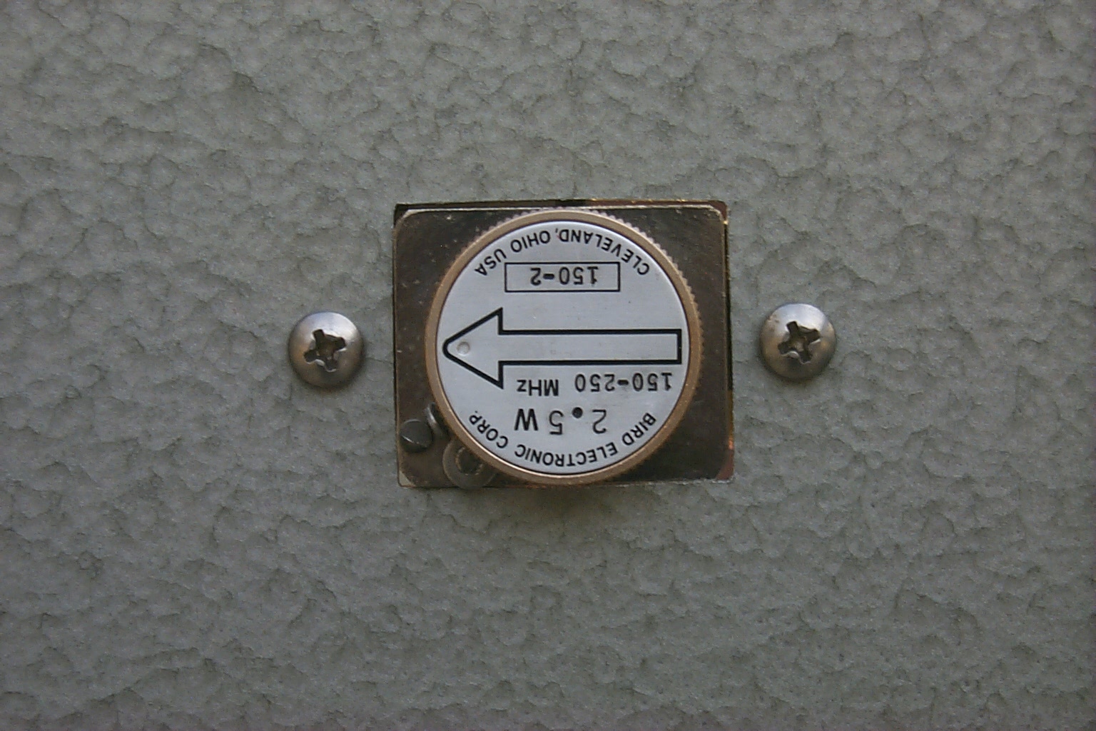
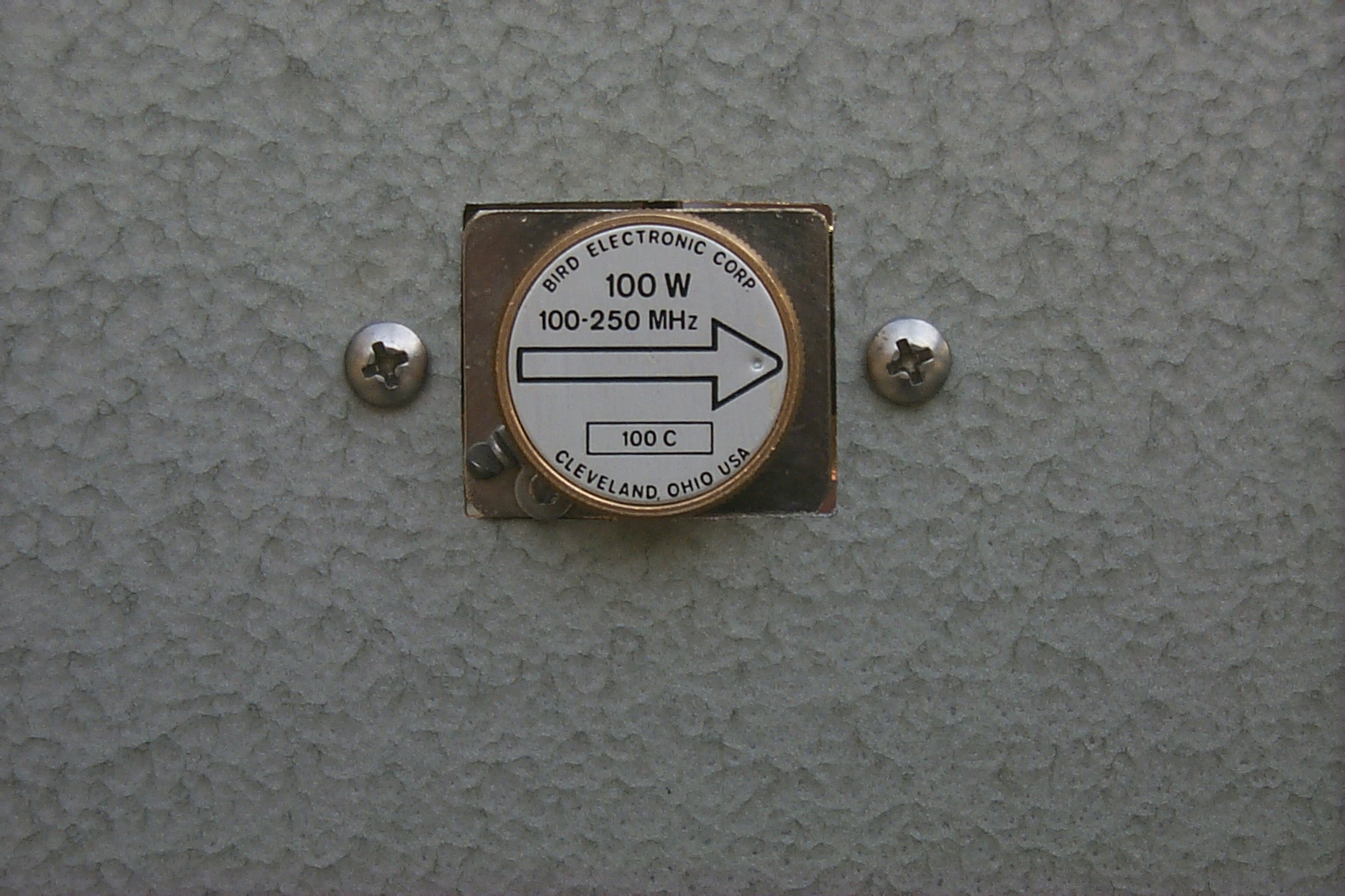
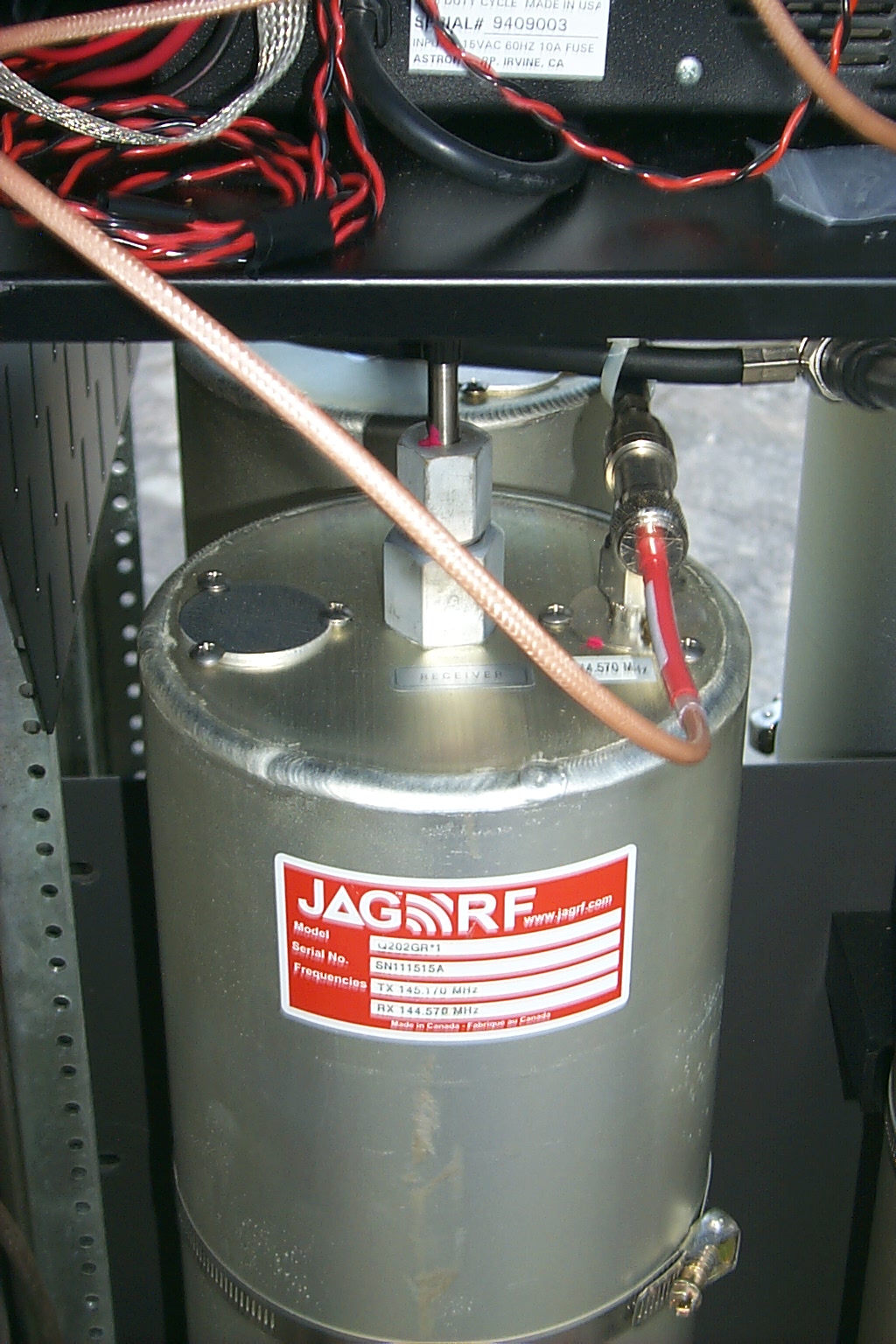
The power out of the duplexer measures 58 watts FWD with 0.65 watts REF for a VSWR of 1.24 : 1 from the JAG Electromagnetics exposed dipole array.
(click on images to enlarge)
Saturday afternoon March 5th 2016 - The GLB Preamp goes back inline...
I was finally able to get the GLB Preselector / Preamp back online.
After rebuilding and retuning it measured 8.4 dB of gain at 144.570 MHz and 6.8 dB of isolation at 145.170 MHz, which has really improved the receiver performance.
(click on images to enlarge)
However I think there could be a few more dBm of receiver performance hiding in the RG-142 RF jumper cables...
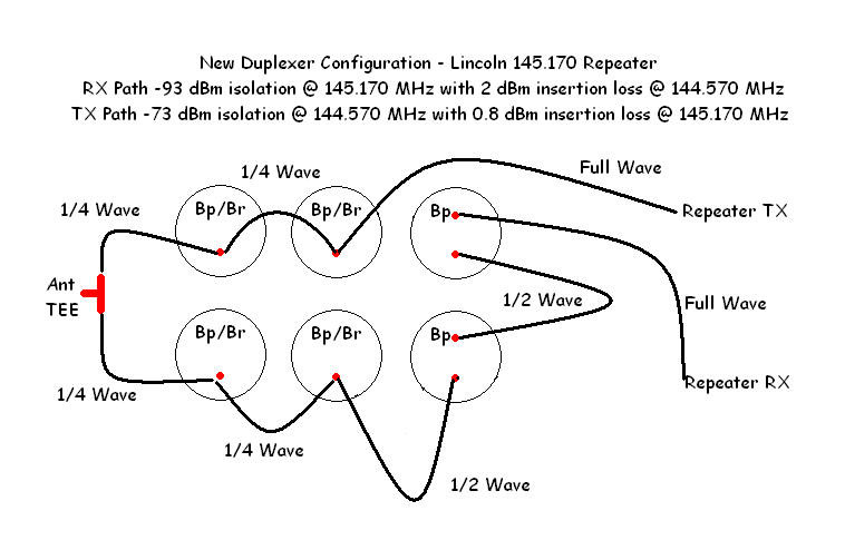
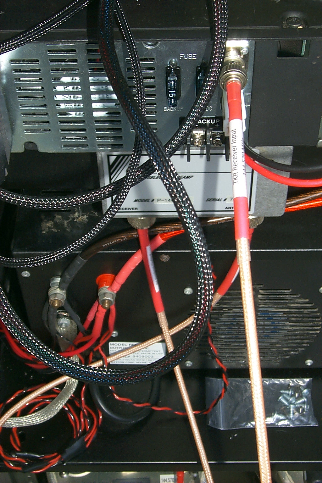
Tuesday evening March 8th 2016 - New JAG RF jumper cables installed on the RX path...
Confirmation, there were 3 more dB's hiding in those RG-124 jumpers.
(click on images to enlarge)
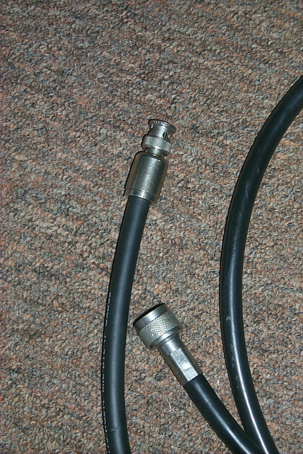
In the photos above are the RG-142 jumpers that I made before making the change. Installing the preamp with these jumper cables did make an improvement however I was convinced that the receiver performance should be better...
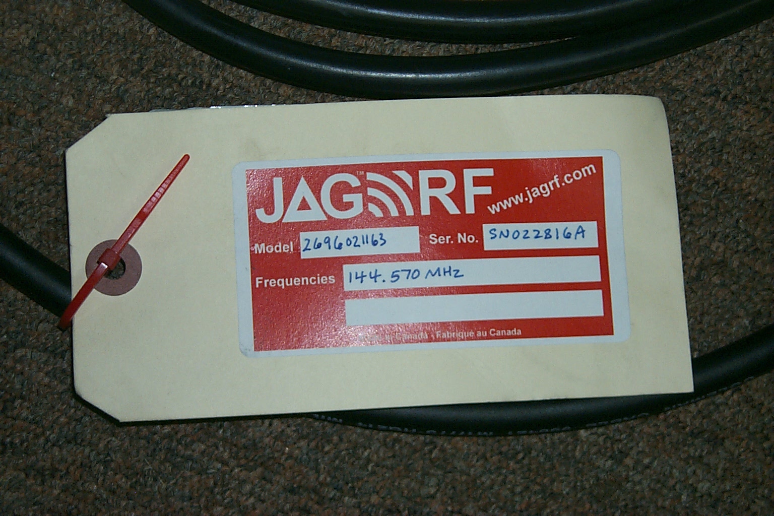
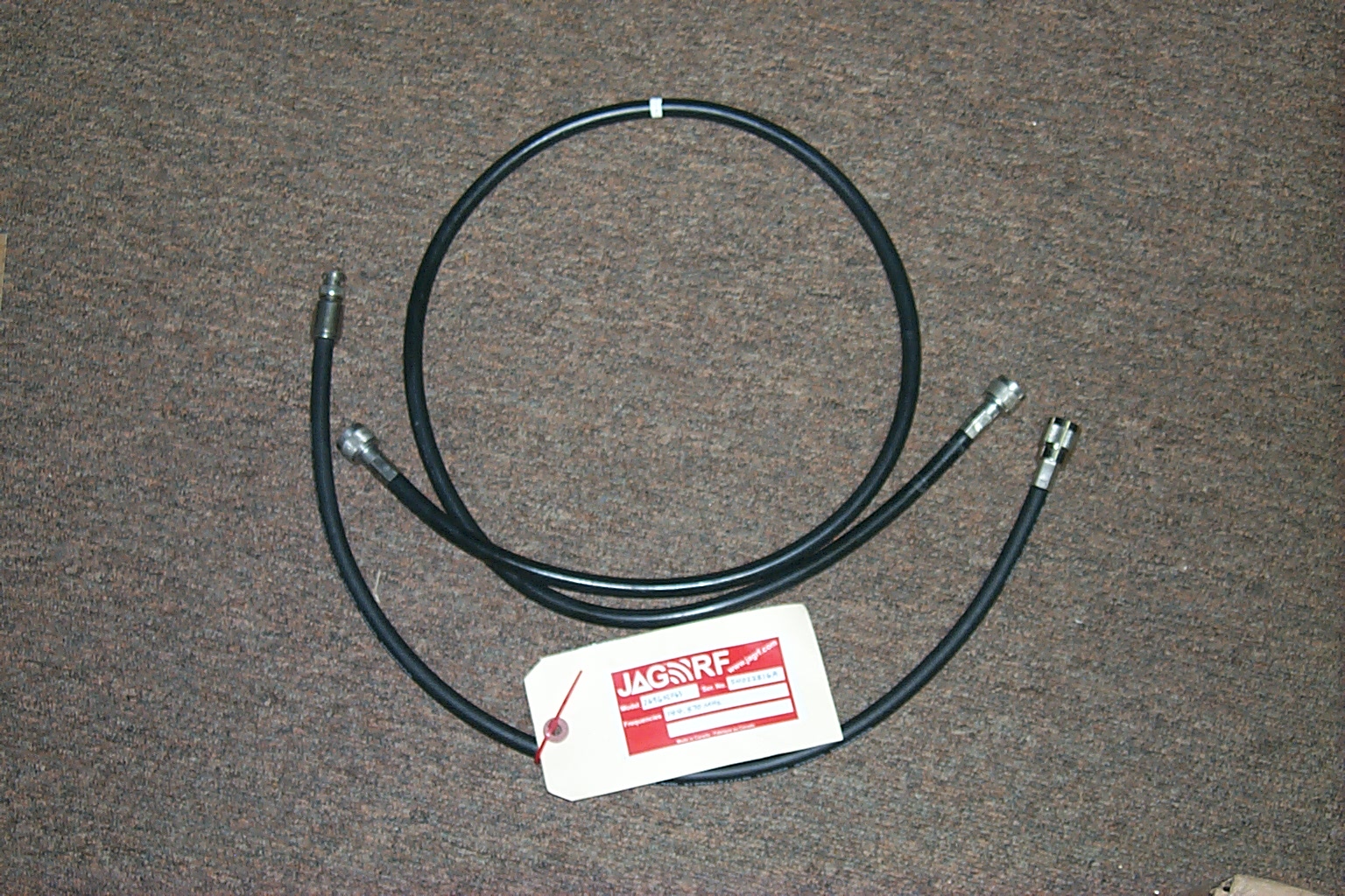
Tuesday evening March 8th I swapped out the RG-142 jumper cables that I had made to interconnect the preamp between the duplexer and the receiver with new custom RG-214/U double shielded "critical length" jumper cables that my good friend Jag from JAG RF made for me.
(click on images to enlarge)
Jag made precision cables cut to the exact electrical wave length of 144.570 MHz, one full wave length and one 1/2 wave length with the correct connectors to make the connection from the duplexer to the preamp input, and from the preamp output to the receivers input.
(click on images to enlarge)
Replacing the custom RG-142 RF jumpers that I made with some custom "critical length" RG-214/U RF Jumpers that my good friend Jag from JAG RF made for me really made a significant improvement getting the Kenwood TKR-750 receiver performance dialed in nicely.
However I still think there could be a few more dBm of receiver performance hiding in the Kenwood TKR-750 receiver front end; with the preamp and new cables optimizing the RX path from the duplexer to the receiver I will like to get the repeater back on the bench at N1BS Labs in West Greenwich to see if we can optimize the repeater performance even more...
This repeater rebuild it still ongoing and this web page are currently...

Return to the KA1RCI Repeater Network Home Page
This page was last updated on 03/09/2016
Send mail to [email protected] with questions or comments about this web site.
Copyright 1995-2016 Steven M Hodell
Copyright in these pages, in the screens displaying the pages and in the information, materials and other content contained in this web site is owned by Steven M Hodell unless other wise indicated and is protected by U.S. and international copyright laws and treaties. The information, materials and other content of this web site may not be copied, displayed, distributed, downloaded, licensed, modified, published, reposted, reproduced, reused, sold, transmitted, used to create a derivative work, or otherwise used for public or commercial purposes without express written consent.