146.460 / 144.960 with PL 67.0 - Established 1986
Scroll to the bottom for the latest update on 08/18/2014
11/16/2010 - The repeater has been moved from the temporary exposed dipole array to the new G7-144 side mounted on the repeater tower...
11/18/2010 - The FSJ4-50B Super-Flex hard-line has been terminated for the UHF link antenna and the repeater is back on the network.
Greg KC1CE built the original 146.460 repeater in 1986 with a one meg split down for an input frequency of 145.460 and he was running it as a stand alone node from Cranston RI. During the same timeframe Joe WA1TAQ and I were building the original 441.350 repeater also running as a stand alone node in Lincoln RI. Greg and I were running linked digital PBBS systems and it was only natural that we link our voice repeaters together as well.
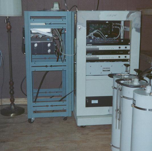
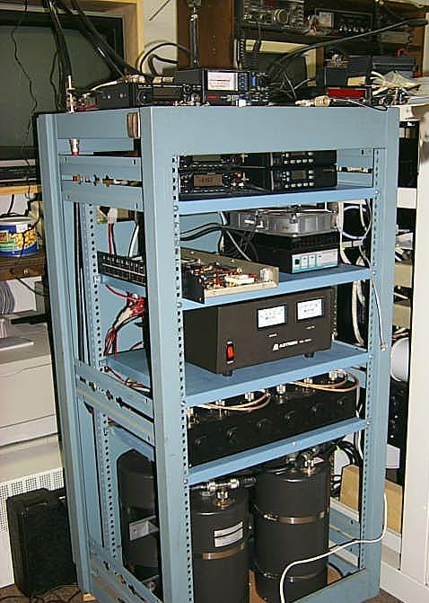
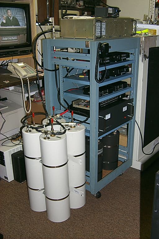
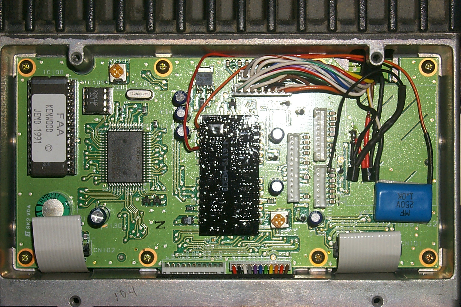
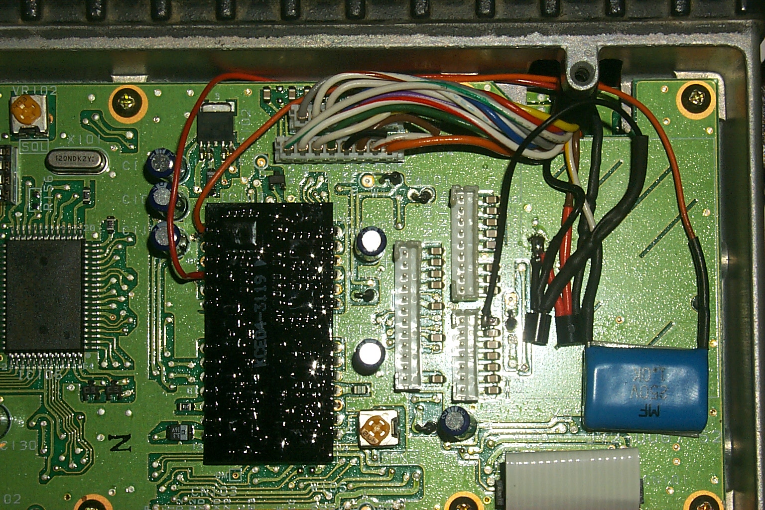
Over the years the 146.460 repeater has been moved around Rhode Island several times. In these rare photos of the original 146.46 / 145.46 repeater taken during the early 90's it was at the Lincoln site with a hardwire link to the 449.325 and 223.960 repeaters.
(click on images to enlarge)
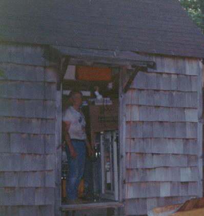
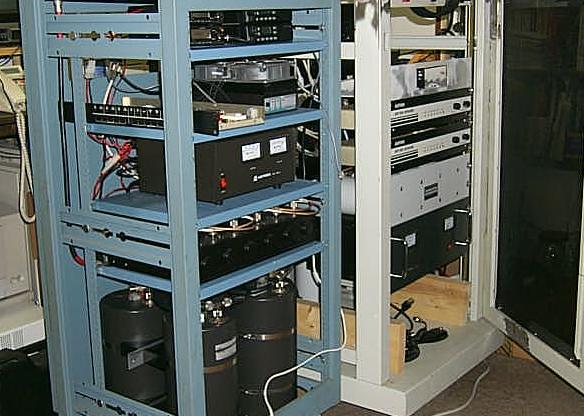
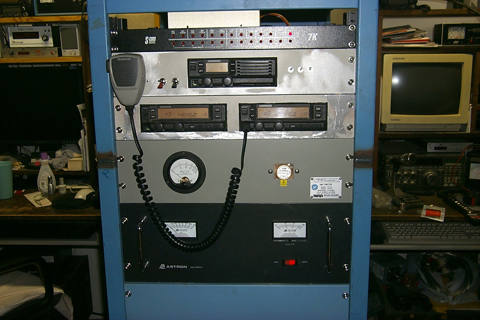
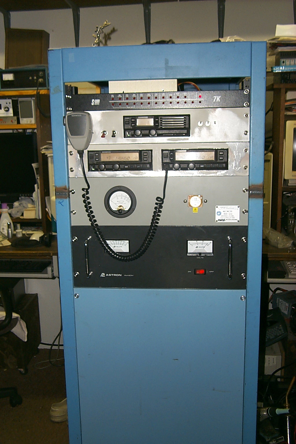
For 15 years 146.460 was linked to the 441.350 repeater in Providence RI. The 146.46 repeater is in the small blue rack to the left with a link cable over to the controller in the 449.325 / 223.960 repeater cabinet. In the photo above on the left you can also see the 350 watt six cavity duplexer. In the photo on the right you can see Bill KA1VKD standing in front of the repeaters in the original shed while we were working on the new repeater shed.
146.460 / 145.460 with PL 103.5 Rebuilt 1994-1995
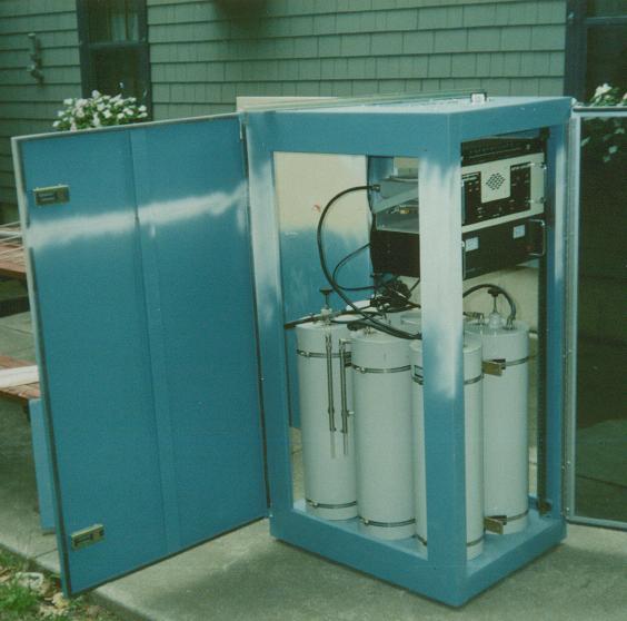
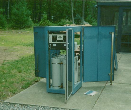
The six cavity 2 meter duplexer was obviously much too large to fit in the small rack that the repeater was in so I had a custom made rack built to just the right size for all the hardware. We started with a standard 7 foot commercial network rack cabinet and cut it down the the appropriate size for the 146.46 / 145.46 repeater.
(click on images to enlarge)
The photos above were taken just before moving the repeater from Lincoln to Hope, RI.
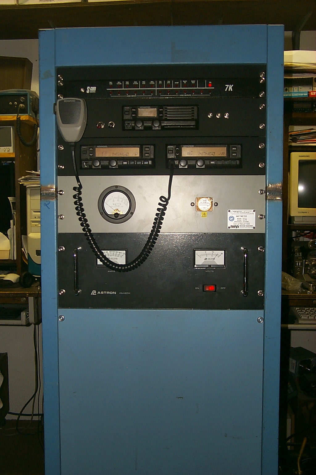
146.460 / 147.460 with PL 67.0 Rebuilt 2004
The 146.460 repeater received a upgrade in late 2004 when the new 447.775 and 927.500 repeaters were built. With the 449.325 and 223.960 repeaters moving from Lincoln to Johnston that left a few vacant repeater antennas on the 80 foot tower in Lincoln. The repeaters moving to Johnston also received an upgrade with a new FF-800 multi-node controller so I took the Scom 7K that had been running 449.325 and 223.960 and use it to built the new 447.775 repeater for Lincoln.
I also inverted the input on the 146.460 repeater with a one meg split up for an input frequency of 147.460 and changed the PL tone to 67.0. This flip of the input frequency better aligned the 146.460 repeater with the ARRL local option one meg repeater pairs. Here are some photos of the various stages during the 146.460 / 447.775 / 921.6125 repeater build.
(click on images to enlarge)
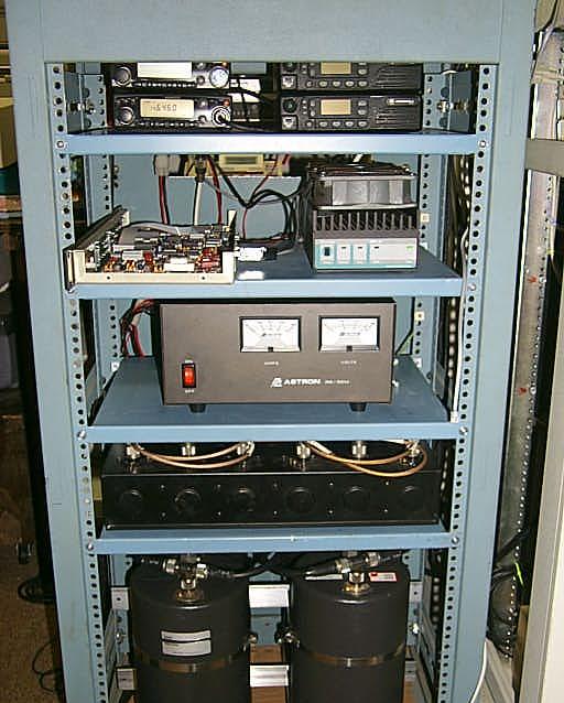
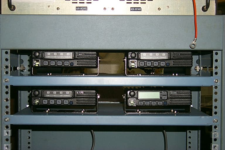
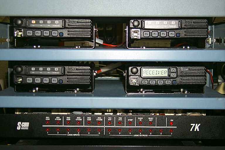
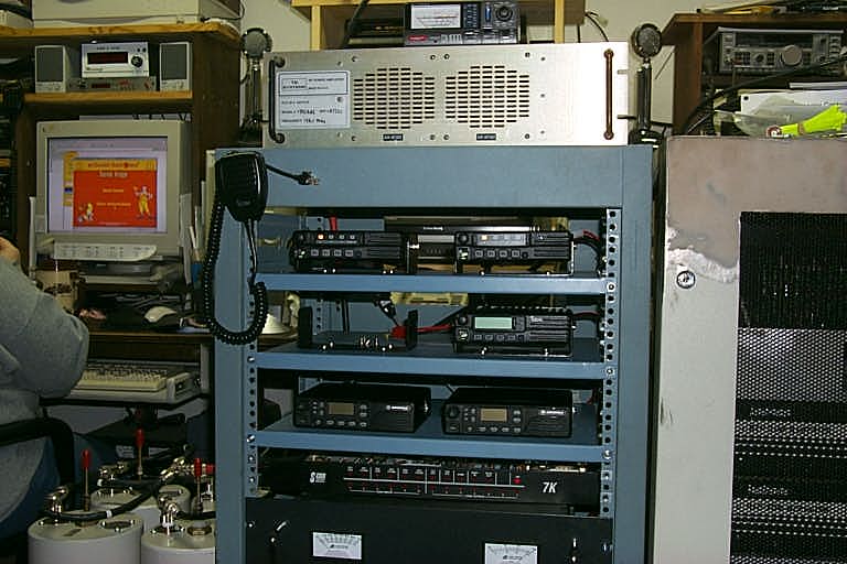
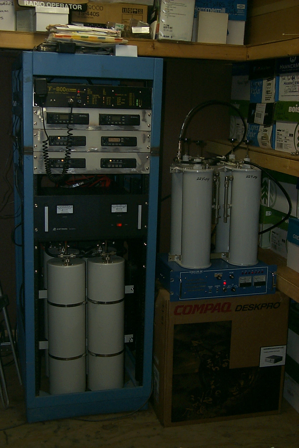
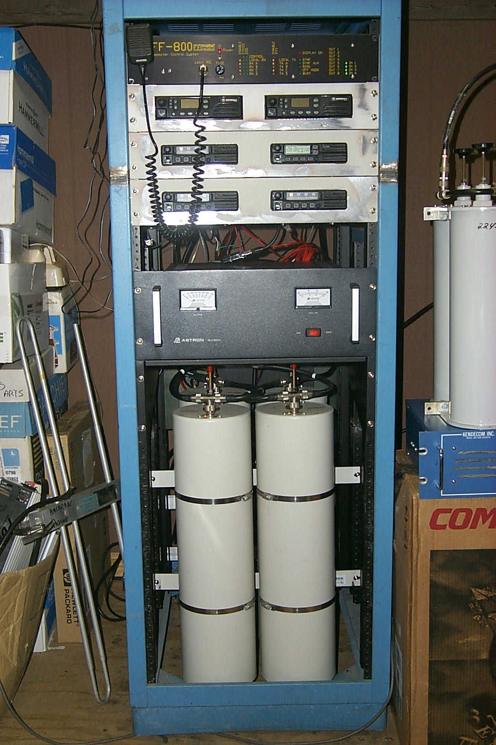
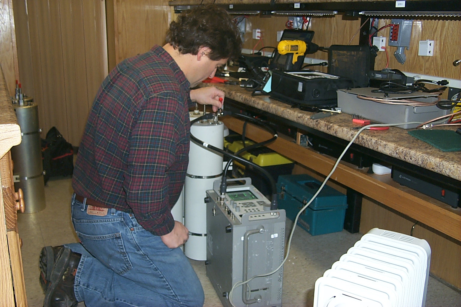
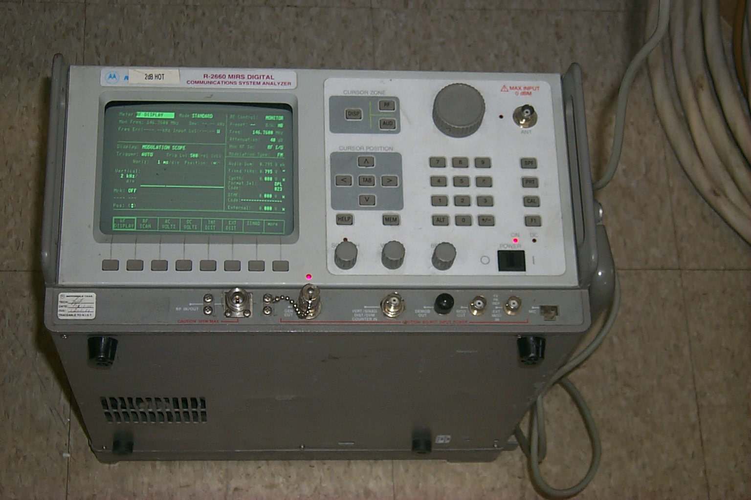
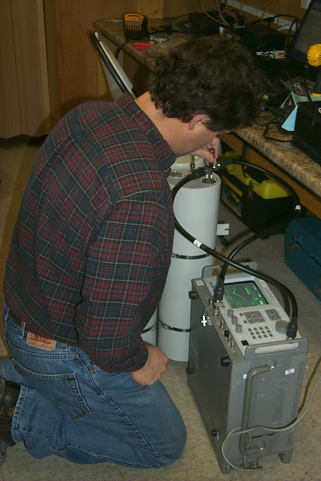
The four photos above show the 100 watt VHF duplexer running the 146.460 / 147.460 repeater while the large duplexer is being tuned for the new input frequency. The other photos show 146.460 and 927.500 on the air using a pair of Kenwood TM-241A's and a set of Motorola GTX radios. You can also see the new 447.775 duplexer in the bottom and the small blue rack tuned and ready for the new UHF RF units. The 223.960 and 449.325 rack is in the back ground also getting an upgrade with a new link radio and the new FF-800 controller.
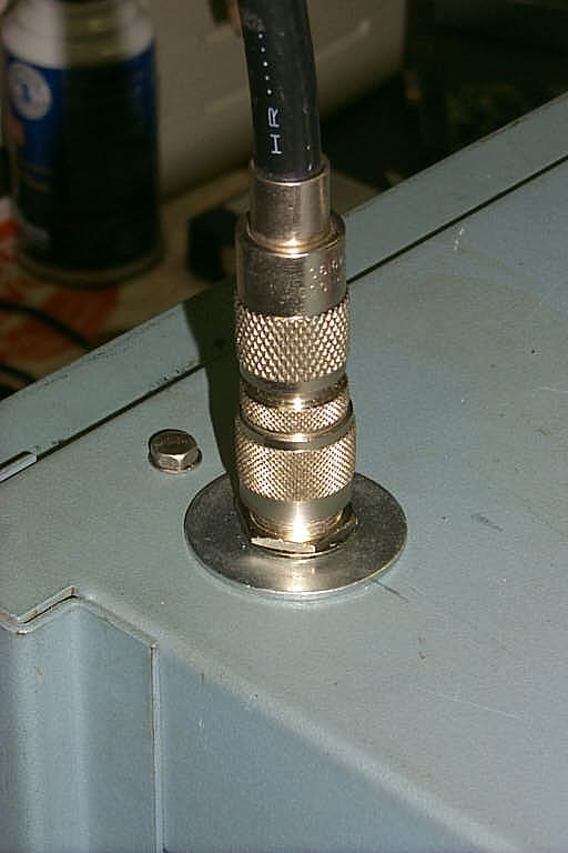
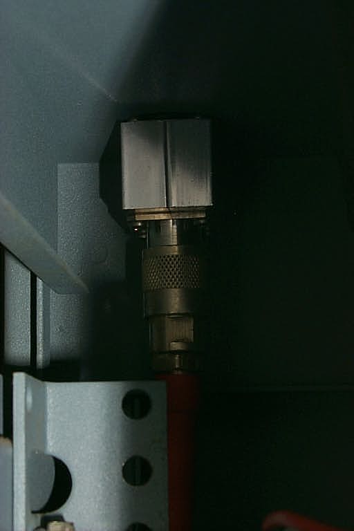
Here are a few photos as I installed the support washer for the Polyphaser and the new Mil-Spec commercial RF units for the 146.460 and 447.775 repeaters.
(click on images to enlarge)
First I took out the rack shelves and the smaller 35 Amp power supply which is being re-deployed for the 146.985 repeater down in southern Rhode Island. Then I mounted the new RF units to the rack shelves and mounted those back into the rack cabinet. Next I installed the larger 50 Amp rack mounted power supply and then the Scom 7K controller.
(click on images to enlarge)
After mounting all the hardware in the rack I turned my attention to the DC power cables.
(click on images to enlarge)
First I routed everything neatly from the RF units to the power supply and then I install the appropriate electrical connectors and fuses.
(click on images to enlarge)
The next step was to make the coax cables to connect the new RF units to the duplexers. I upgraded the VHF duplexer with another set of Sinclair cans similar to the UHF duplexer for the 447.775 repeater.
(click on images to enlarge)
You can also see the Motorola 900 MHz GTX radios for the 921.6125 repeater in several of these photos.
(click on images to enlarge)
The repeaters were temporally built in the original small rack cabinet that Greg used for 146.460 back in 1986. This small rack has been the home for several of the different KA1RCI packet nodes and voice repeaters over the past 18+ years. I am currently building a much larger rack cabinet that will support the 146.460, 447.775, and 927.6125 repeaters.
There is also a second FF-800 in the plans for this three node repeater system which should hopefully be online in the summer of 2005.
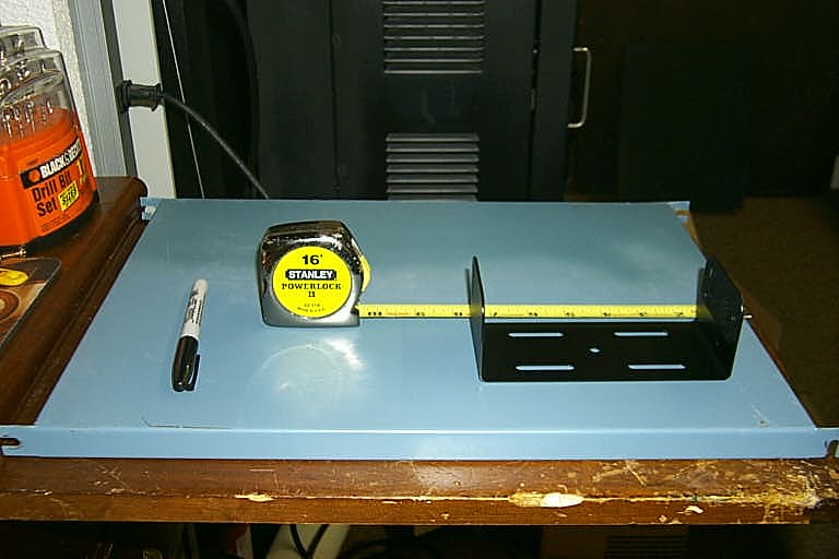
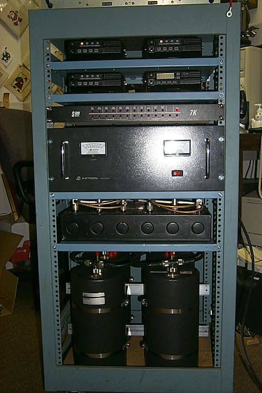
I finally was able to have my brother-in-law Scott cut down an eight foot rack cabinet to just the right size for the Lincoln repeaters. There is only 64 inches of clearance under the storage shelve and I needed 58 inches of room for the hardware from the three repeaters. 146.460 / 447.775 / 921.6125
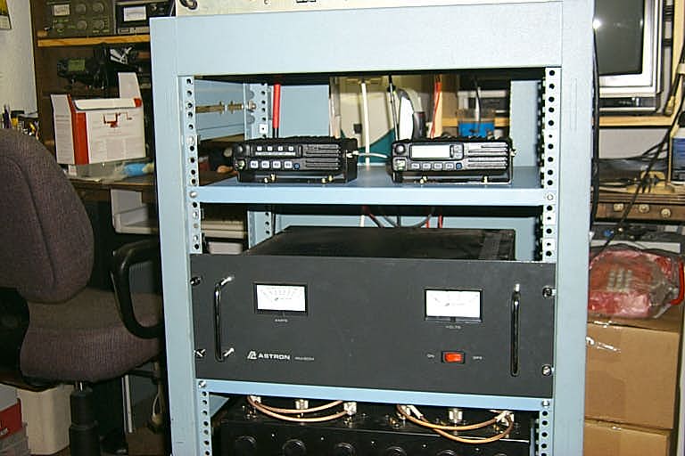
These two photos show the repeaters running with a temporary desktop power supply while I look for a larger rack mount unit.
(click on images to enlarge)
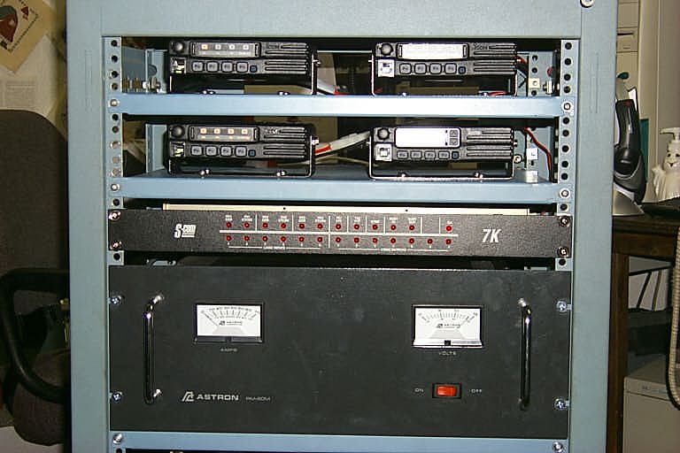
These photos were taken after the new larger rack mounted power supply was installed.
(click on images to enlarge)
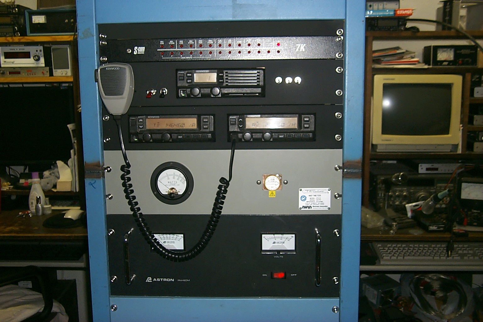
146.460 / 147.460 with PL 67.0 Upgrade 2006
With the success of the Kenwood TK-30 series radios deployed across the network I decided to upgrade the Icom radios on the Lincoln 146.460 and 447.775 repeaters with TK-30 series radios. I also decided to break the repeater apart, for years they have been running in the same rack cabinet with the one FF-800 controller. This arrangement was by design to save space however the normal maintenance and occasional repairs highlighted an issue. I had to shutdown all three repeaters to work on any one of them, and repairs we difficult because all the hardware was packed tightly into the one rack cabinet
New Rack Cabinets
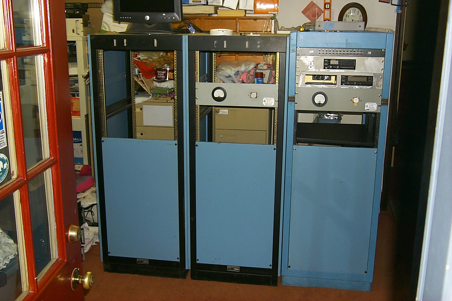
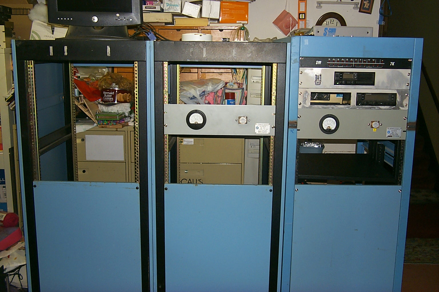
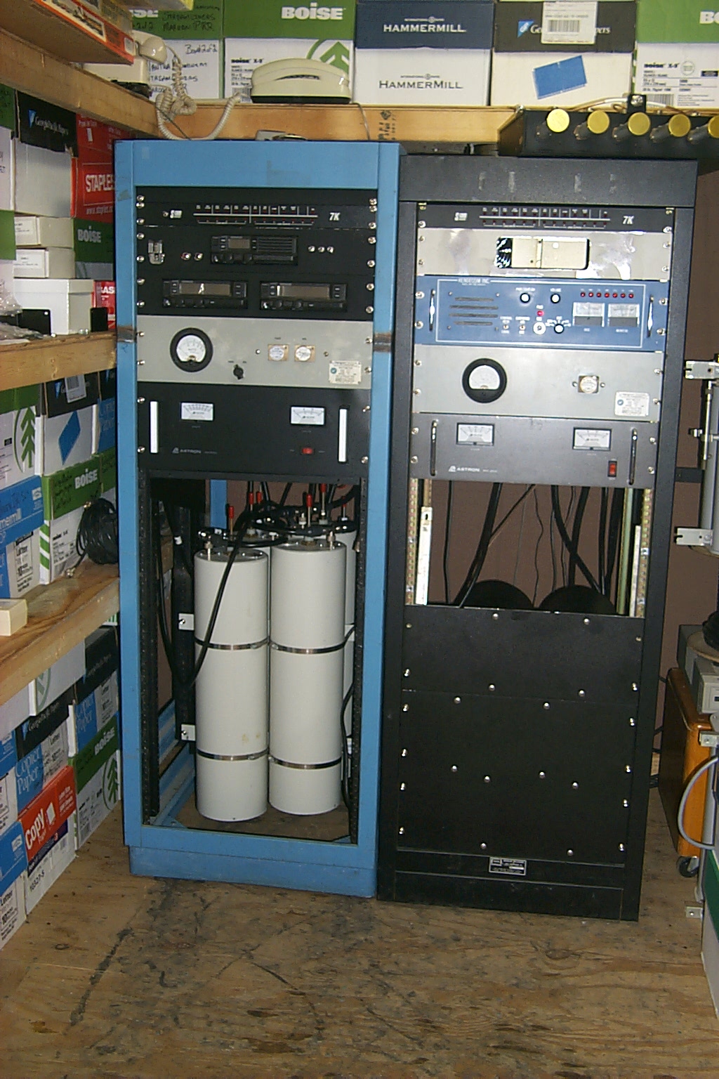
I was able to find two more cabinets very similar to the original rack that my brother-in-law Scott had cut down to fit in the repeater vault. These two new cabinets would allow me to rebuild the Lincoln repeaters into individual racks each with their own controller making repairs and maintenance much easier.
These two photos show the three racks lined up in the house as I started rebuilding all the hardware. Syl N1DKF help getting the cabinets ready tracking down wheels and other specialty hardware for the racks.
(click on images to enlarge)
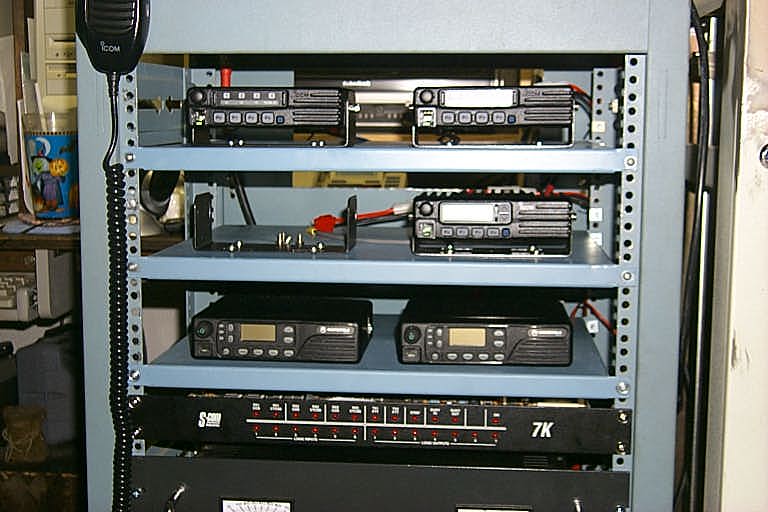
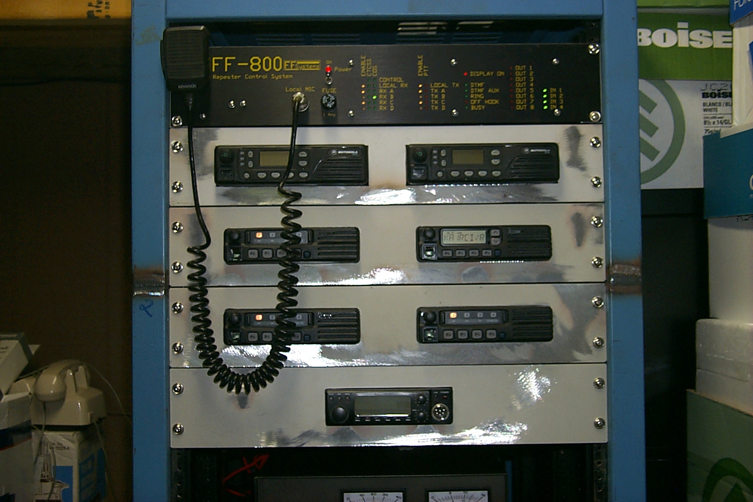
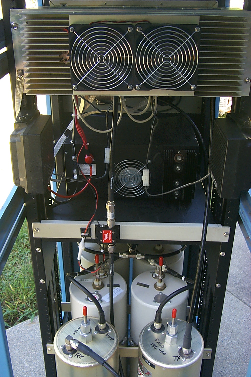
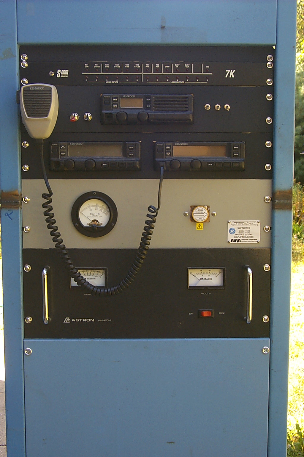
Starting with the original rack, which is several inches deeper, I would rebuilt the 146.460 hardware using the new TK-30 series radios, a new S-Com 7K controller, and I added two more VHF Band-Pass cavities along with a 20 dB GasFET pre-amp to improve the receiver performance.
Kenwood TK-30 Series Radios
The TK-30's received the standard ABI-Labs modifications for Audio & COS signaling to the 7K controller and I added a second mod for CTCSS signaling.
(click on images to enlarge)
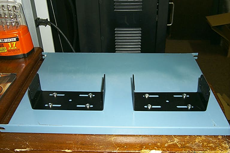
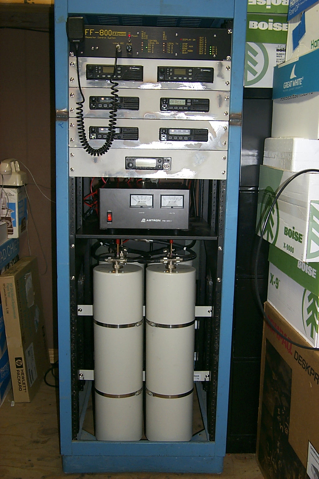
With only one repeater in the rack cabinet there was room for a Thruline "Bird" inline VSWR panel. Then using the custom rack mounts my Brother-in-law fabricated for the TK-30 radios I mounted all the hardware in the rack to measure for new hard-line and control cables. Once the hardware was mounted, and all the cables had been completed I was able to break everything down and paint all the rack mounts. You can see in these photos where Scott shortened this rack to fit into the repeater vault.
(click on images to enlarge)
After a few days of testing in the radio room at the house, and having Dad hang a new UHF link antenna on the 80 foot repeater tower, we dragged the repeater back the vault. Once it was moved back to the 80 foot tower the receivers performance improvements were very noticeable. I would still like to make some fine tuning adjustments on the cavities to maximize the receiver however we are going to wait until the 17 year old Diamond antenna and aging Belden 9913 feed-line have been replaced.
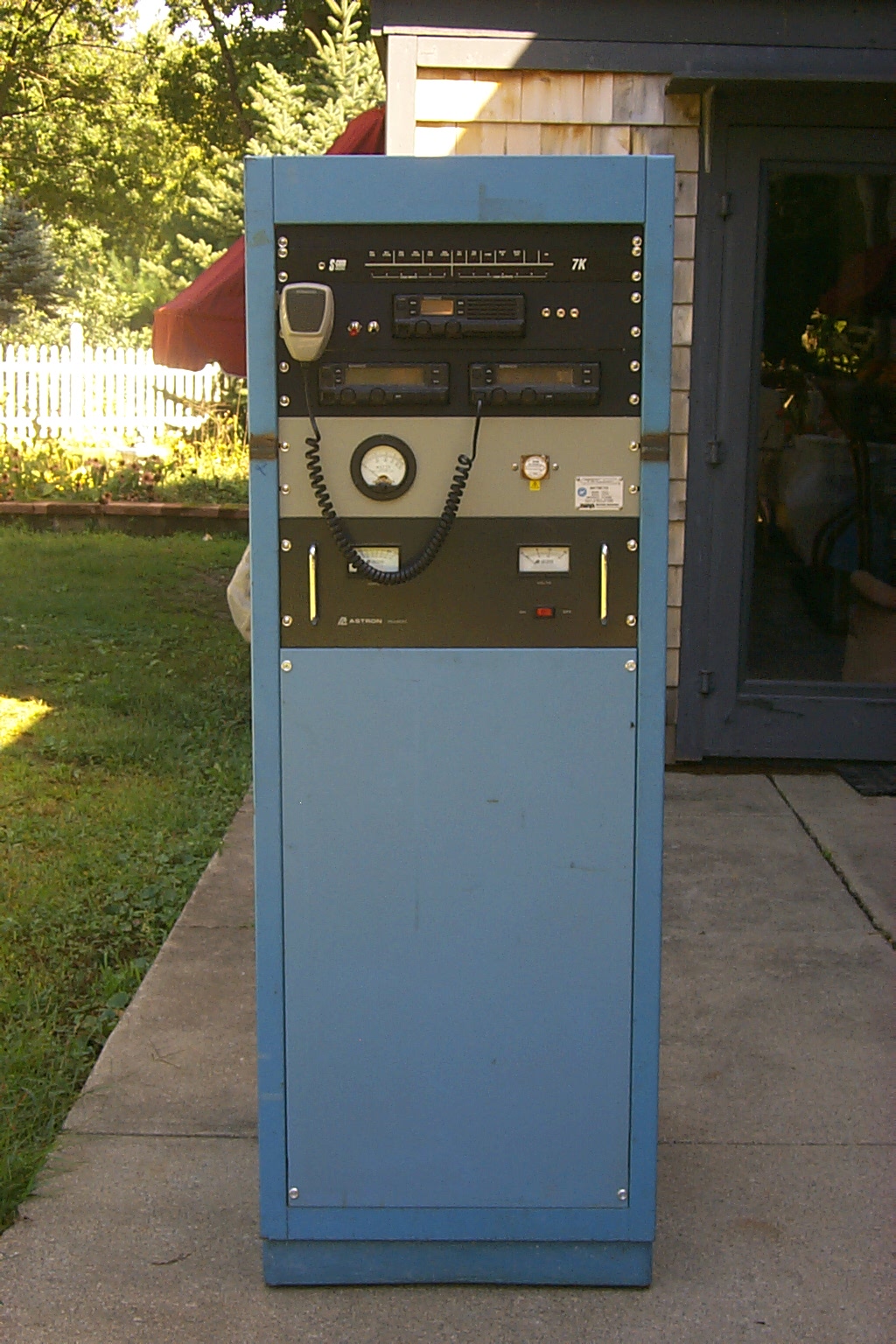
(click on images to enlarge)
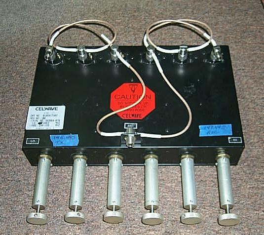
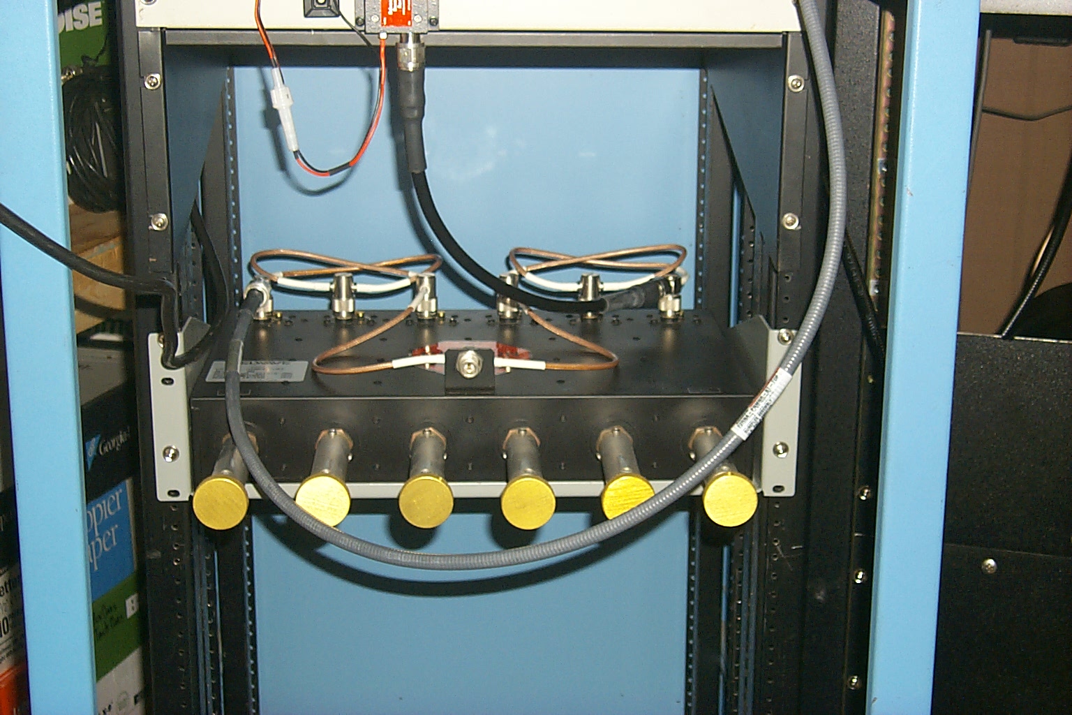
Of course we need the duplexer close up for John WA1ABI
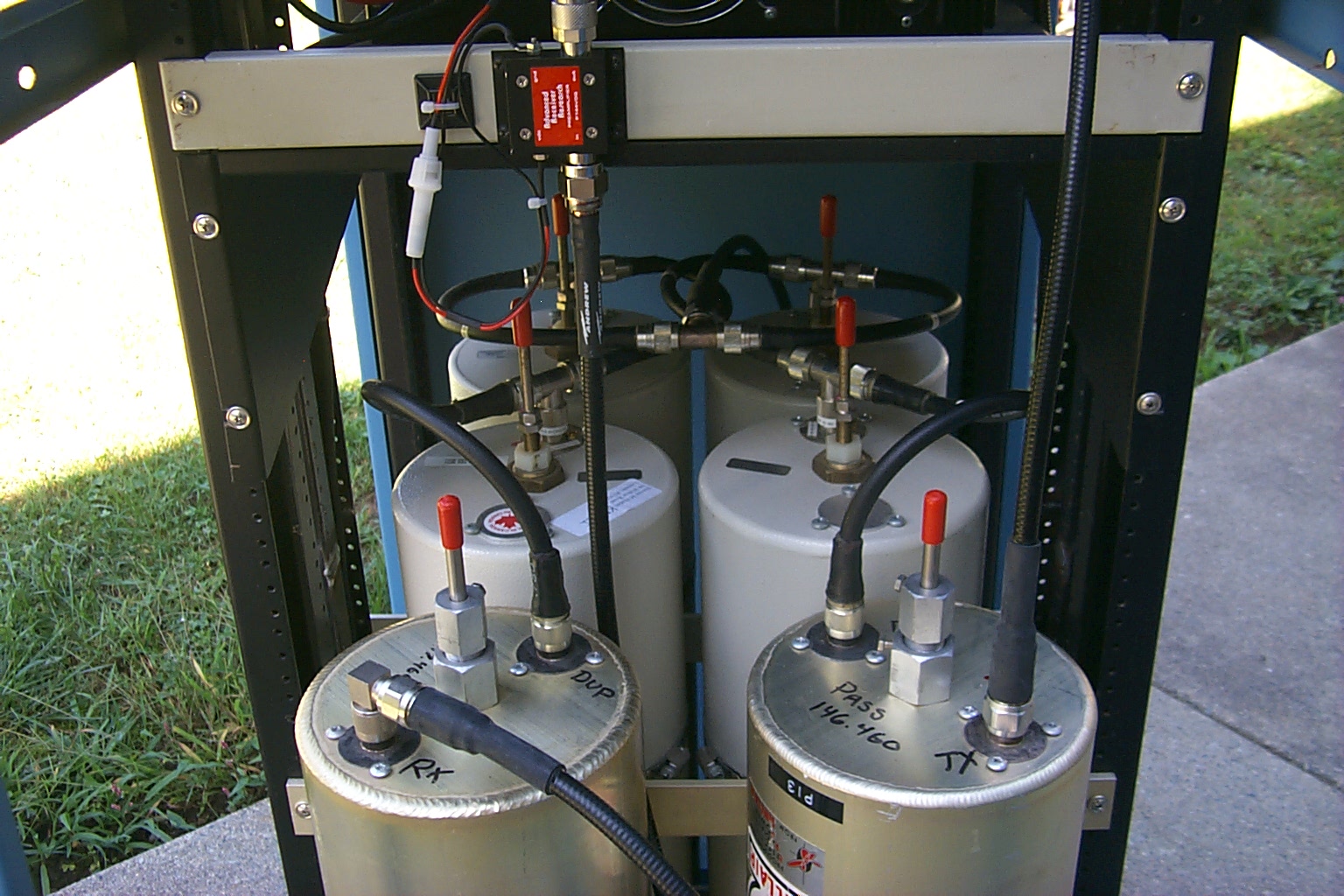
(click on images to enlarge)
Duplexer reconfiguration Jan 2010
(click on images to enlarge)
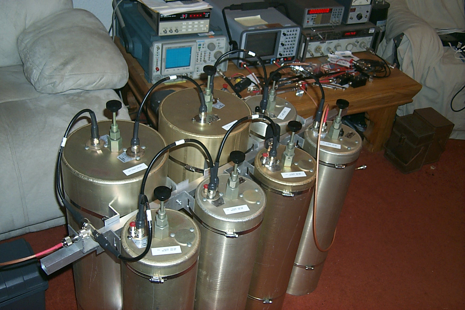
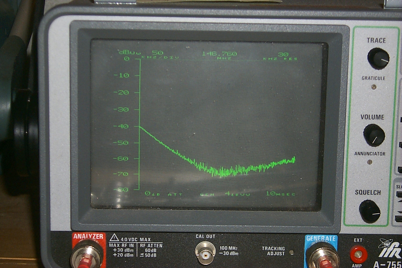
Over the Christmas 2009 / New Year 2010 holiday season Roland N1JOY, Pete AA1PL, and I spent many hours upgrading the 146.760 repeater located in Situate, RI. During these activities Roland & I worked with Brian N1BS during a marathon session tuning the new cavities for the .76 duplexer in the middle of my living room. We spend hours trying different coupling loops and configurations but could not get the performance that we expected.
This are photos of the 146.760 duplexer during our marathon tuning session...
(click on images to enlarge)
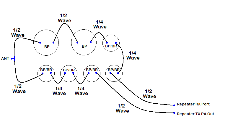
After additional research on the internet and more hours of troubleshooting in the HAMCOW Roland indentified that the jumper cables that make up the phasing harness between the different cavities needed to be either 1/4 wave or 1/2 wave depending on which cavities they were connected to. The Bp/Br cavities needed 1/4 wave cables and the Bp cavities needed 1/2 wave cables. Once this issue had been identified Roland was able to make some new jumpers and the tuning / performance of the cavities improved dramatically.
(click on images to enlarge)
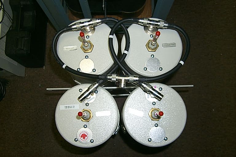
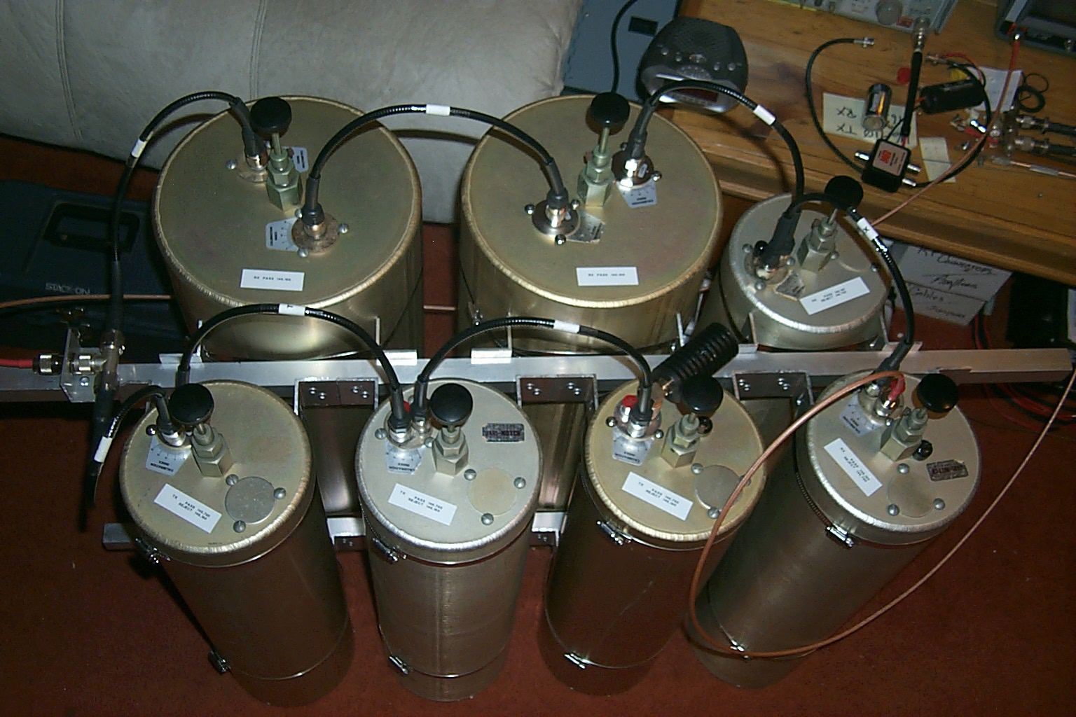
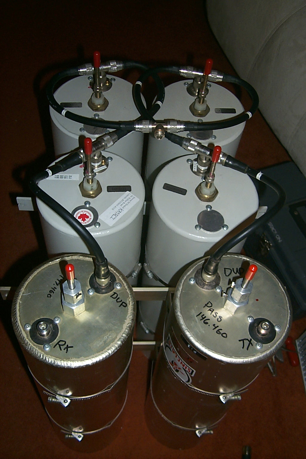
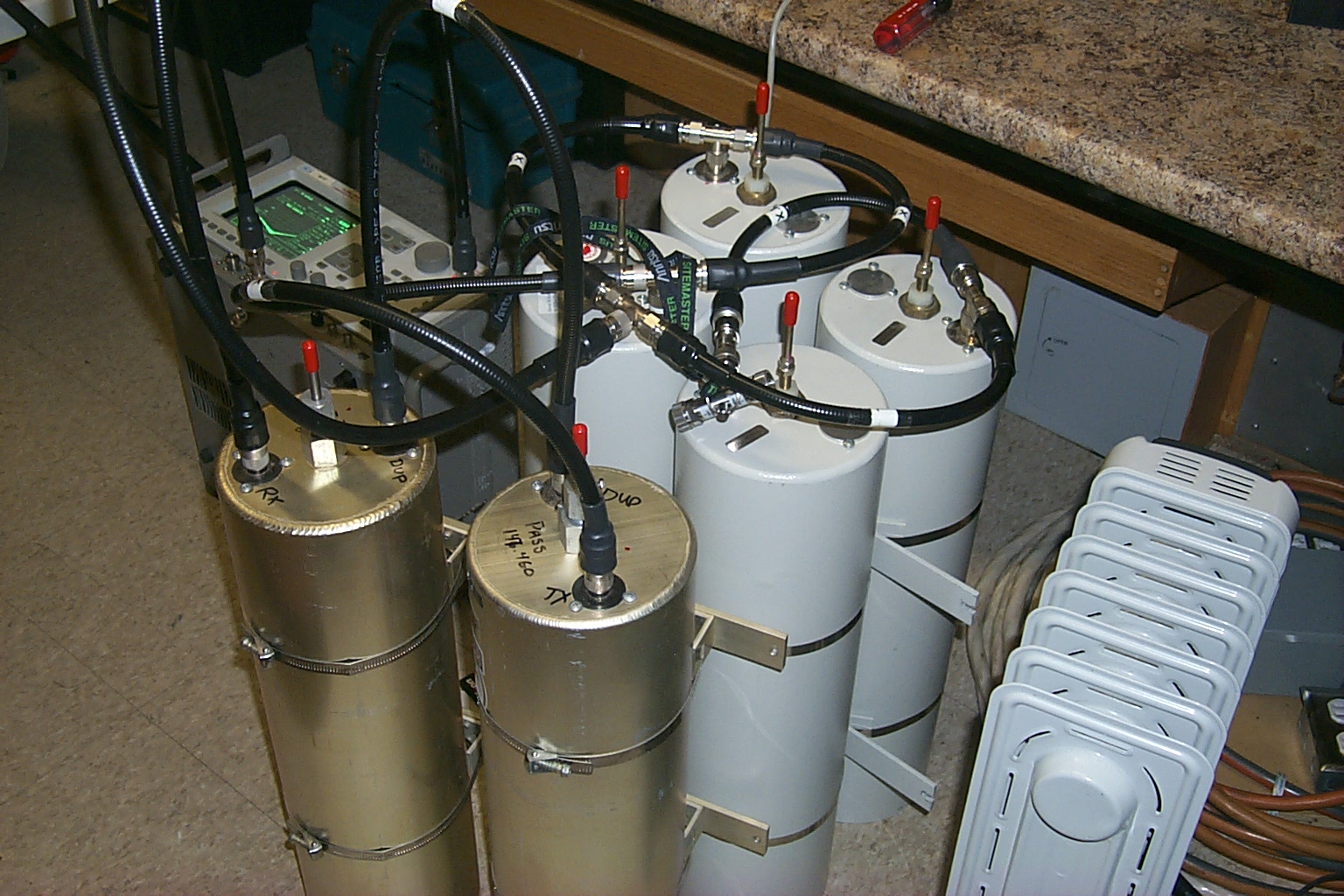
With this information in hand I asked Roland for help making the same configuration changes to the Lincoln 146.460 cavities to try and improve the receivers performance. The cavities were configured with three filters on each half of the duplexer, two Bp/Br and one Bp for TX, and the same configuration for RX.
This photos shows the original 3 x 3 configuration.
(click on images to enlarge)
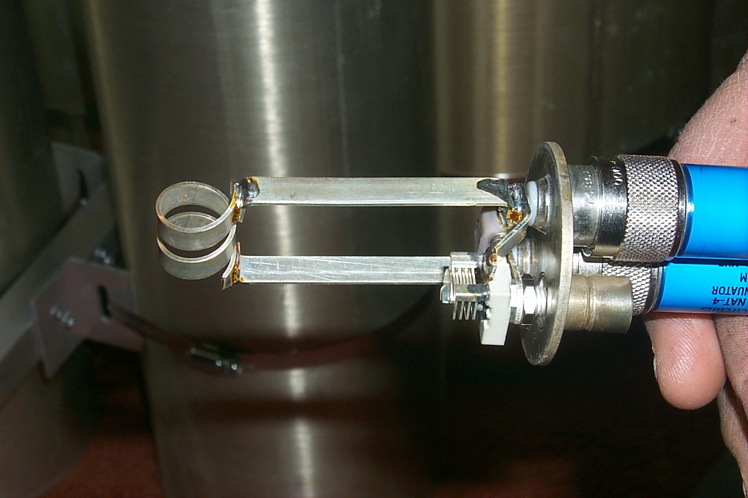
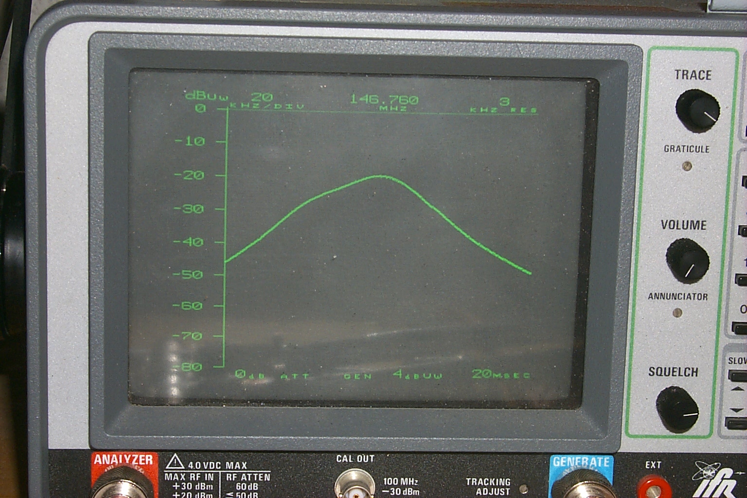
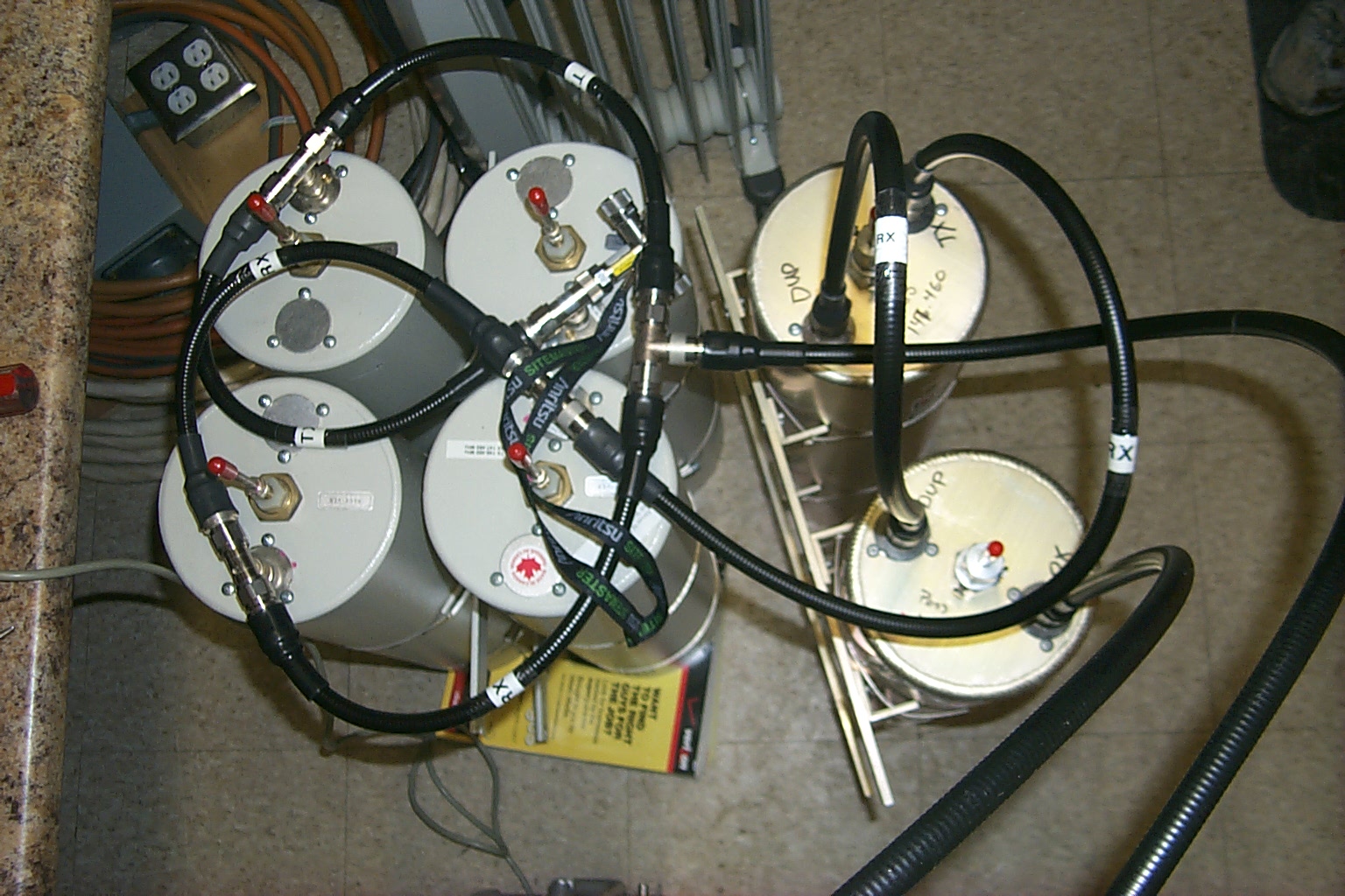
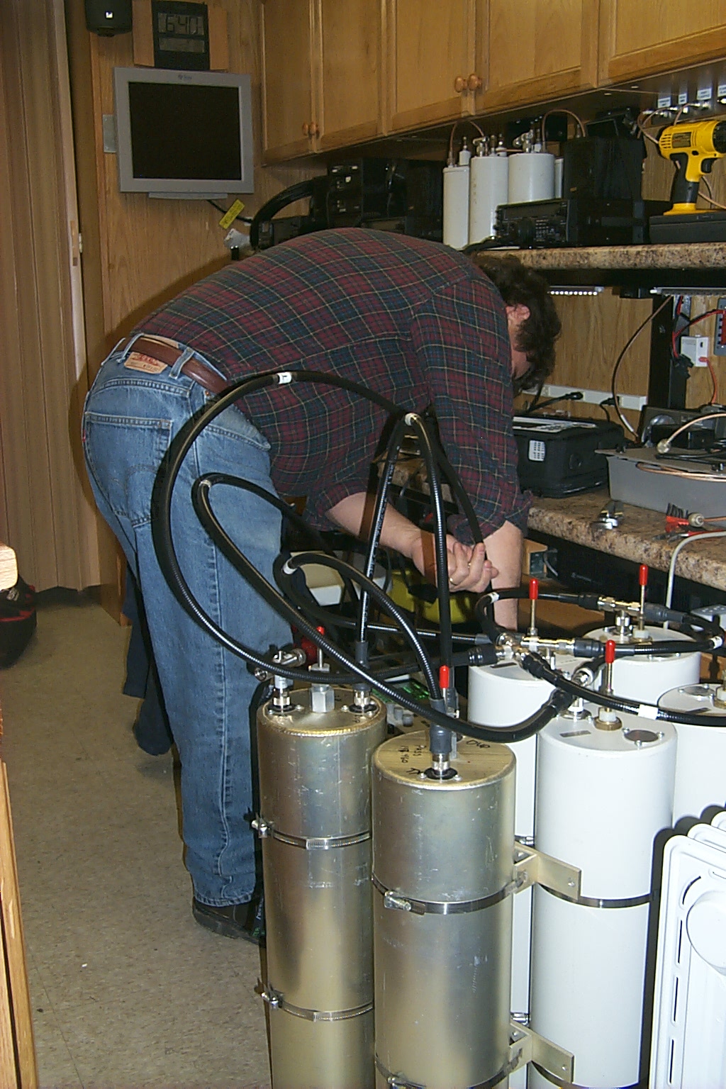
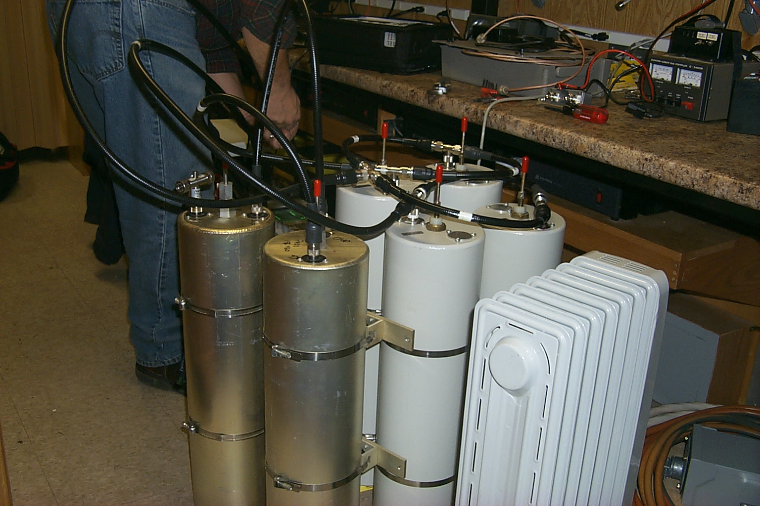
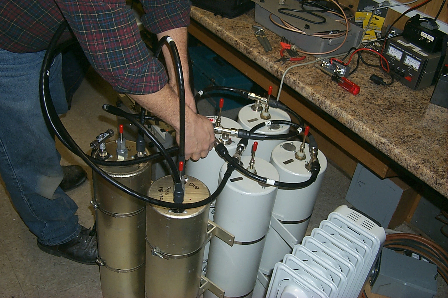
The first step was to replace the original braded coax jumpers with new FSJ4-50B Heliax jumpers cut to exact 1/4 wave, 1/2 wave, and full wave lengths for the TX and RX frequencies. Then we moved both of the Bp cavities to the receive path changing the 3 x 3 configuration to a 2 x 4 configuration. Next we retuned all the cavities with the new jumpers in the new configuration. The results were impressive and we were able to improve the performance of the receiver path thru the cavities by 3.0 dB by reducing the insertion loss.
These photos were taking in the HAMCOW while Roland was working his magic...
(click on images to enlarge)
(click on images to enlarge)
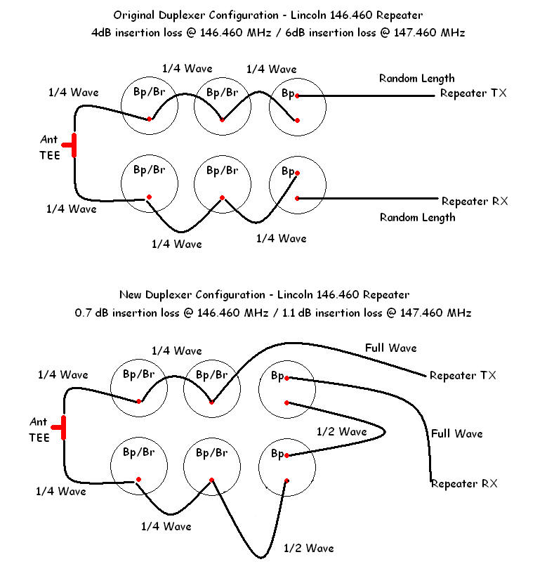
This diagram shows the Before and After configuration of the filter cavities and the performance improvements we were able to achieve by replacing the jumpers, changing their lengths, and moving both Bp cavities to the receiver path.
(click on images to enlarge)
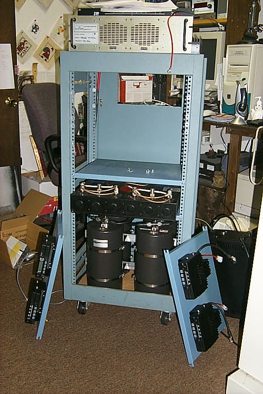
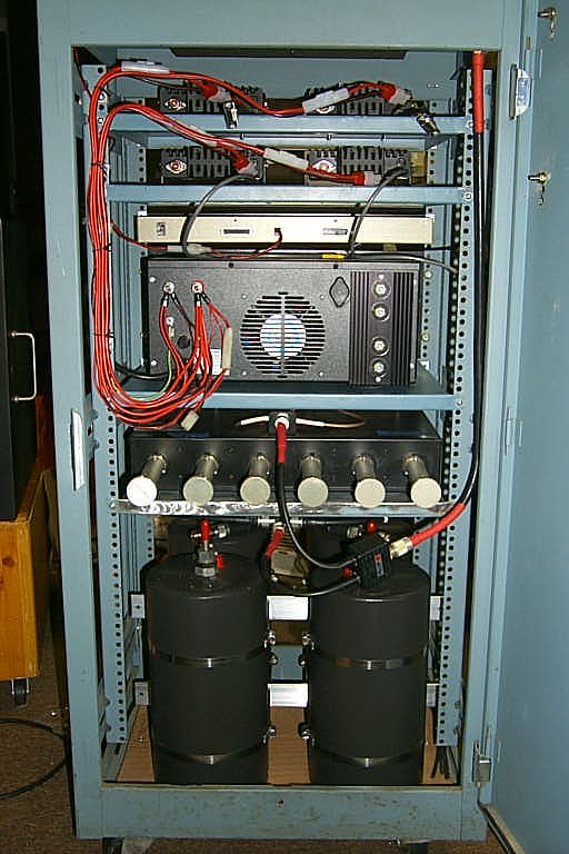
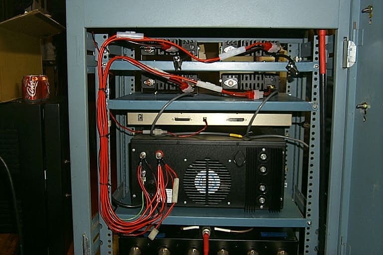
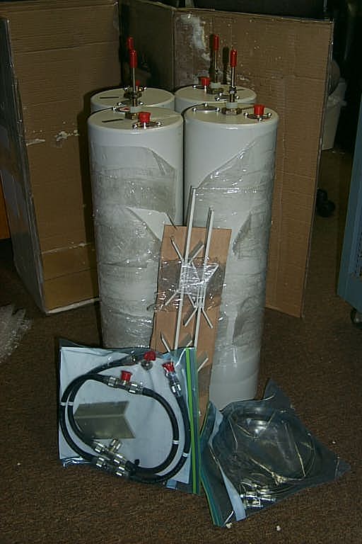
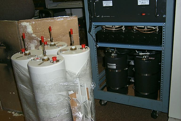
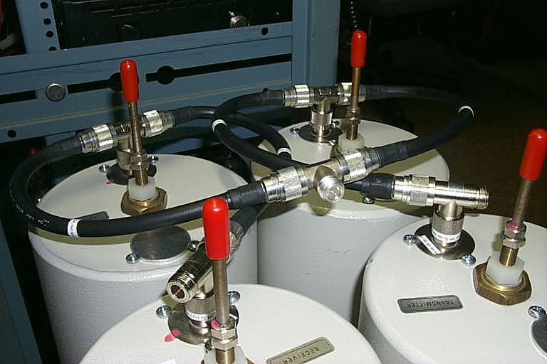
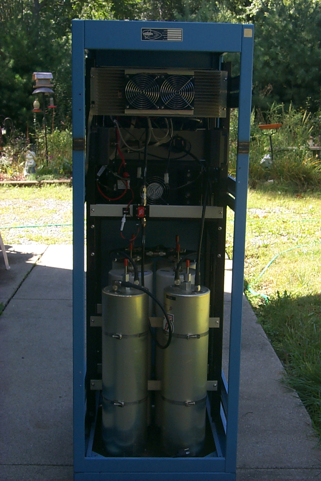
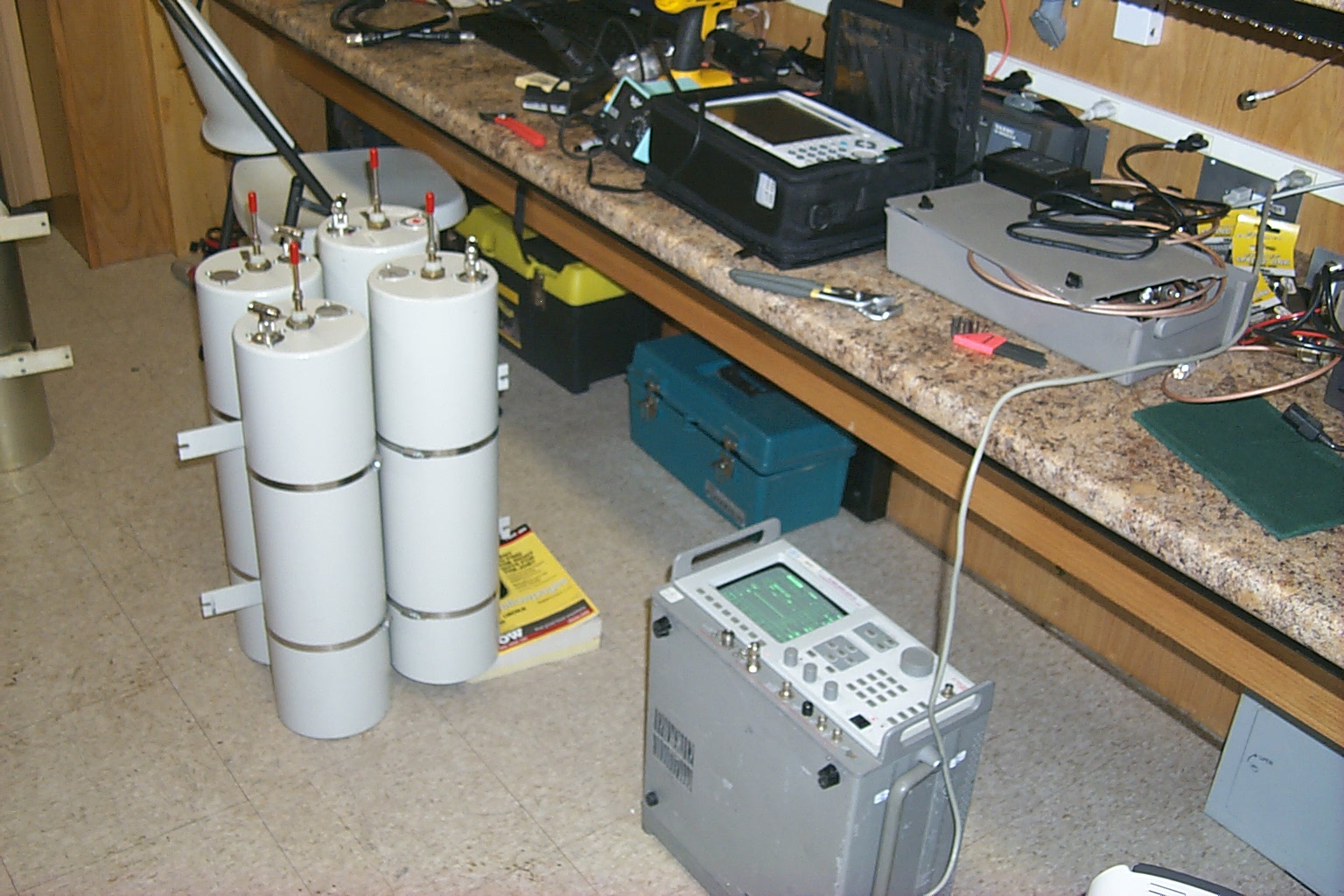
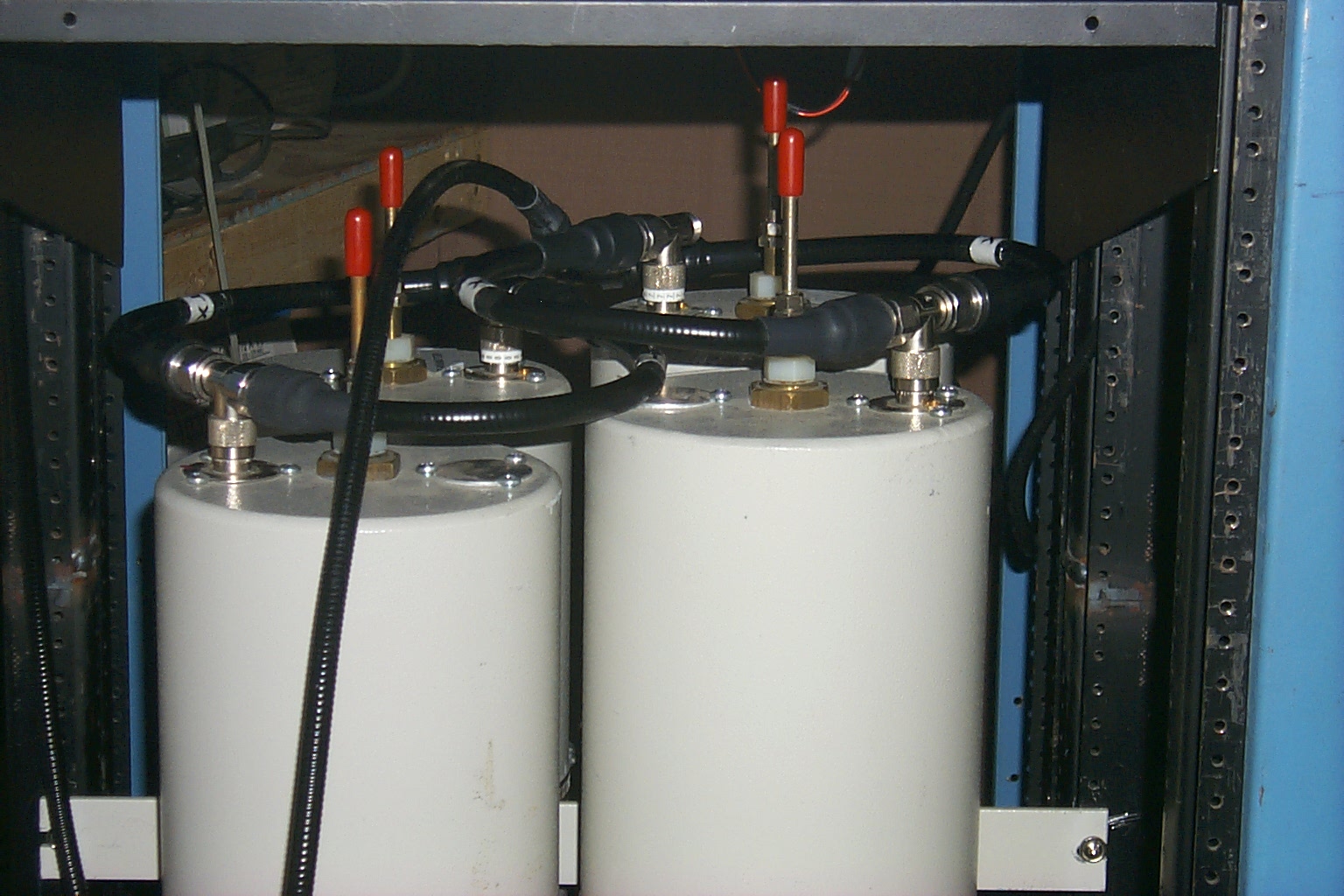
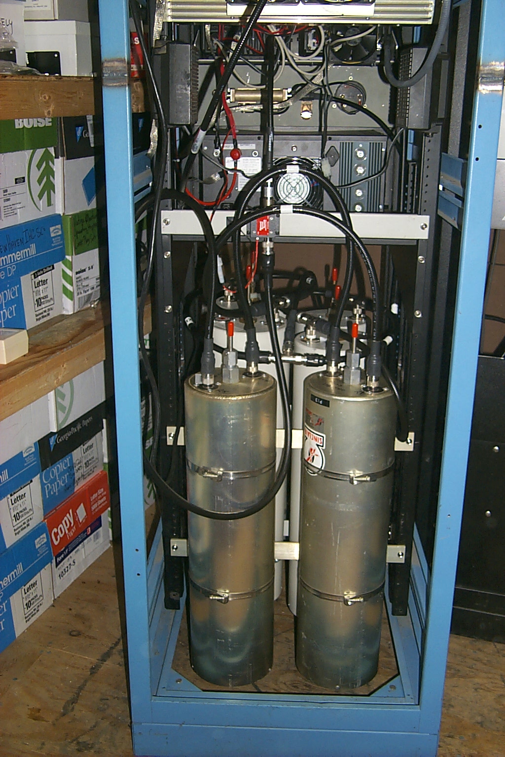
With the cavities reconfigured and retuned in the HAMCOW it was time to drag everything back to the repeater vault and installed the duplexer back in the rack. I had quickly installed the a small six cavity duplexer in the rack to keep the repeater on the air while Roland and I reconfigured the primary cavities.
In these photos you can see the reconfigured cavities staged in the repeater vault and the small six cavity duplexer.
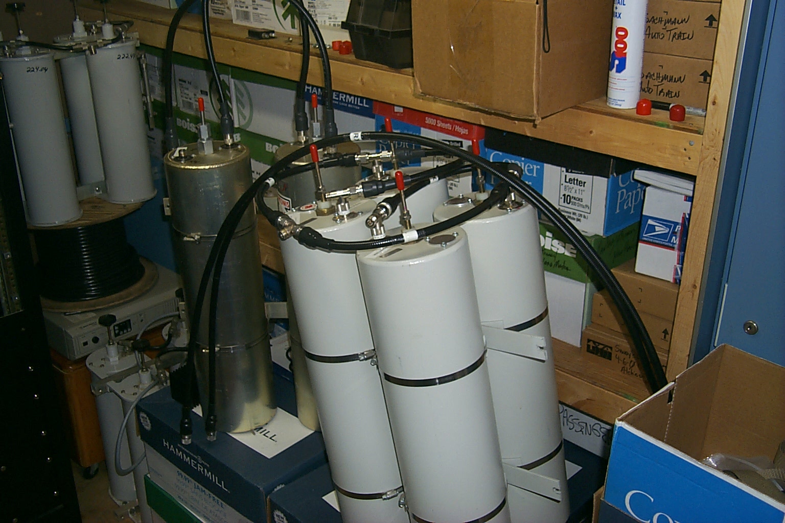
(click on images to enlarge)
Putting it all back together...
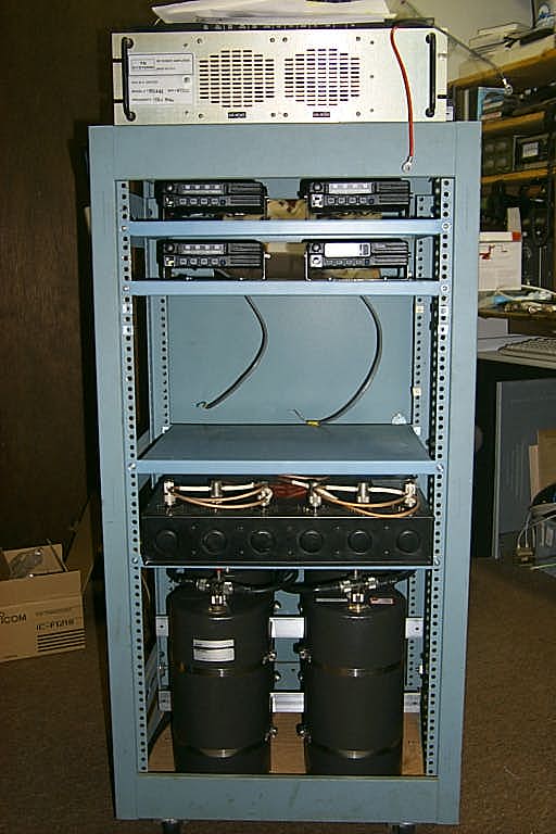
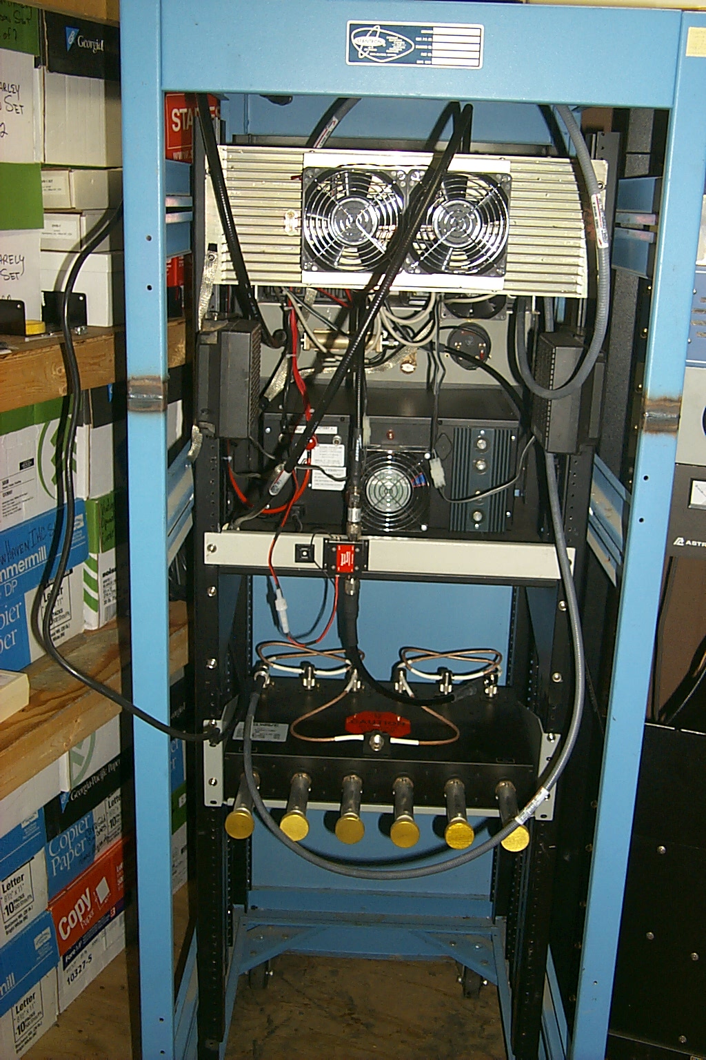
In these photos I have removed the small six cavity duplexer and bolted the four Bp/Br cavities back into the rack.
(click on images to enlarge)
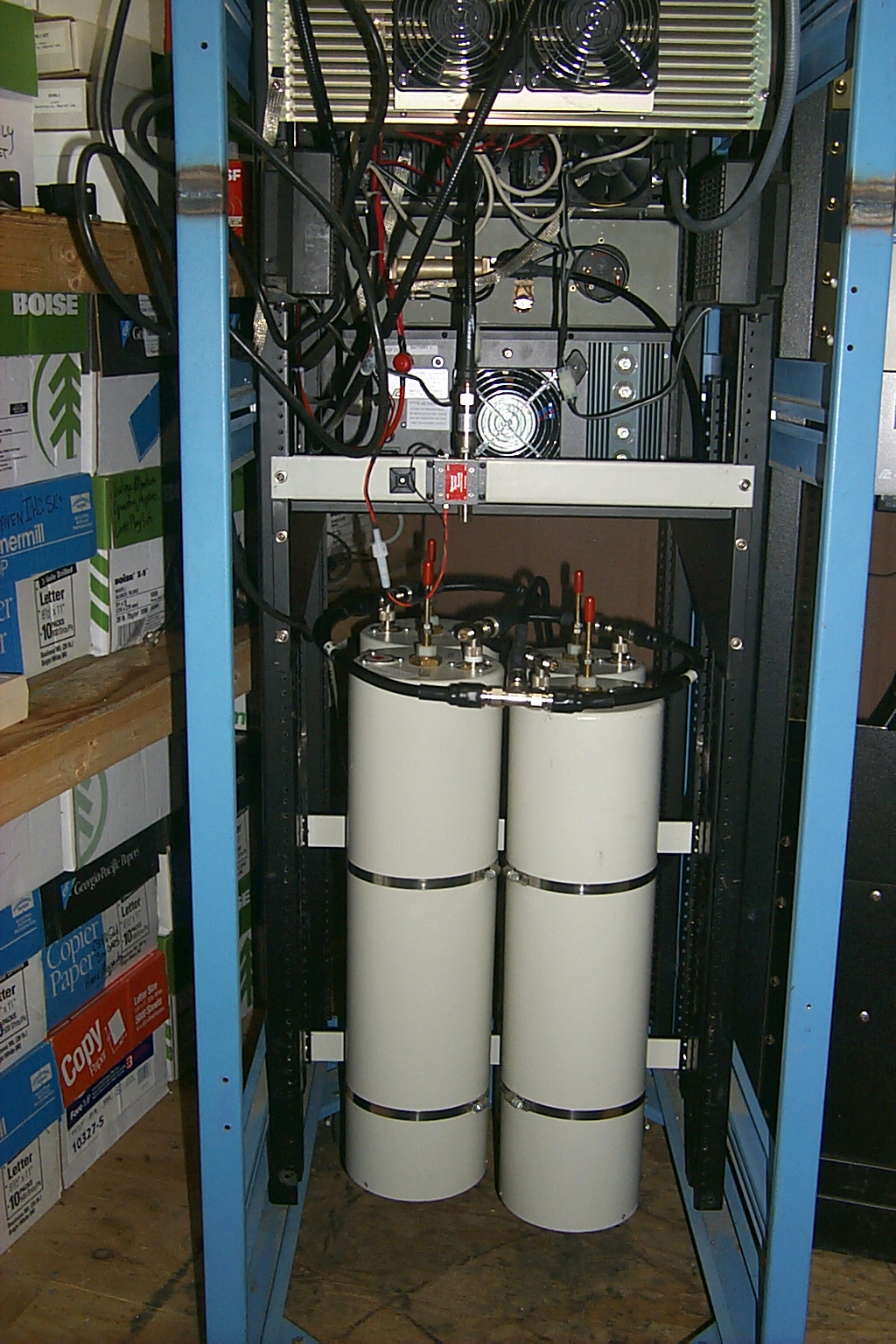
Here I have bolted in the two Bp cavities back into the rack.
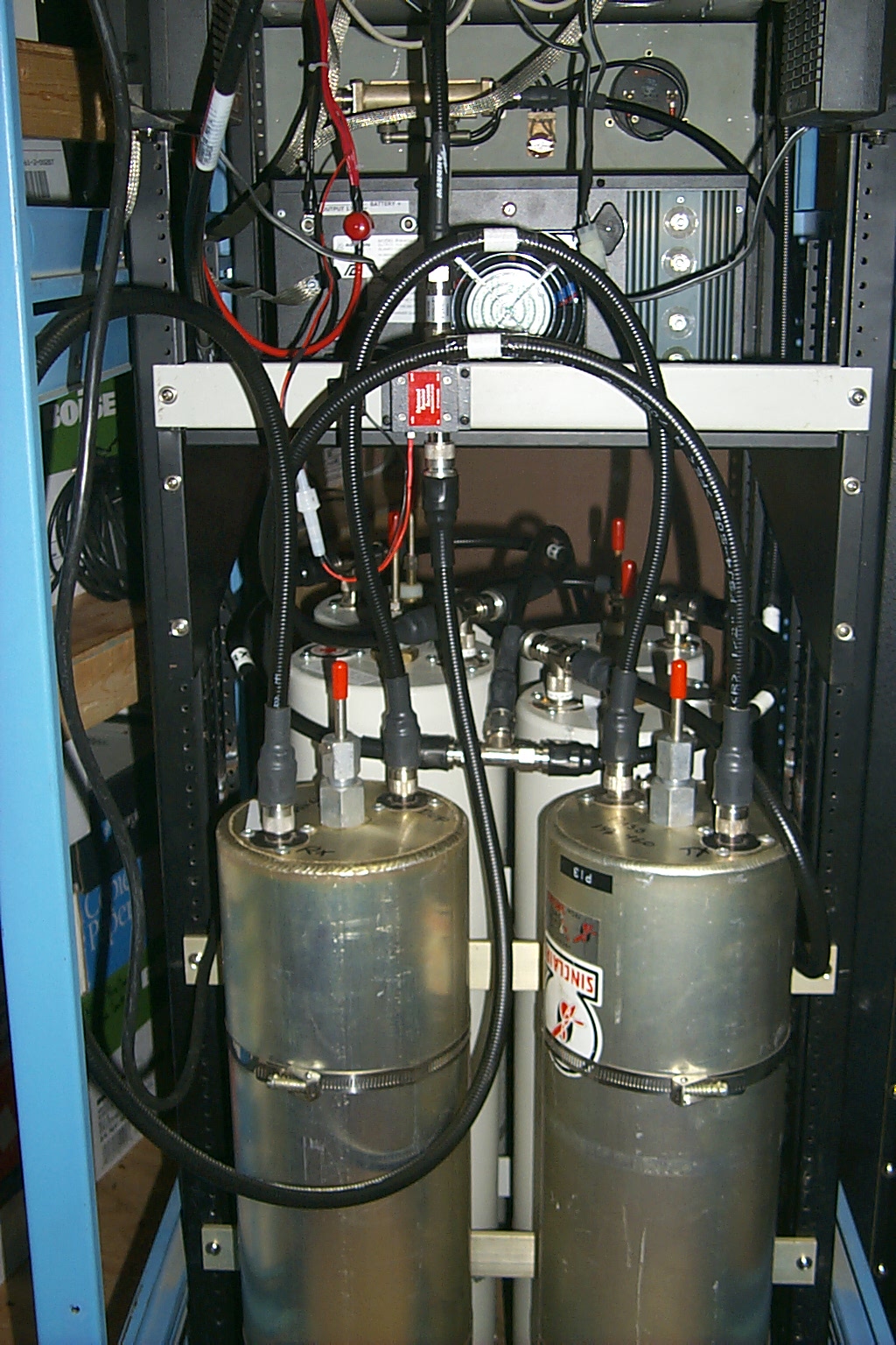
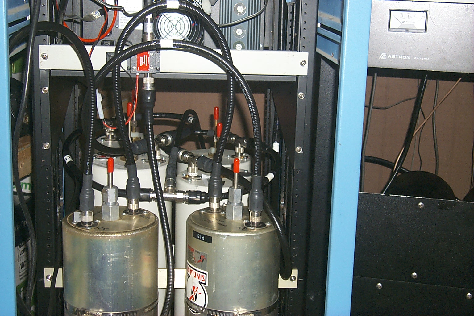
(click on images to enlarge)
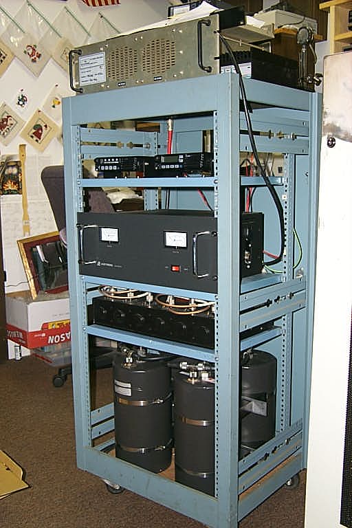
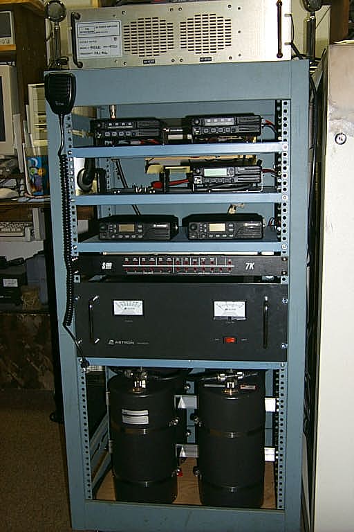
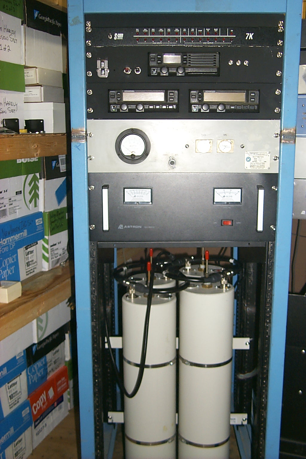
These photos show the repeater back on the air with the newly reconfigured cavities
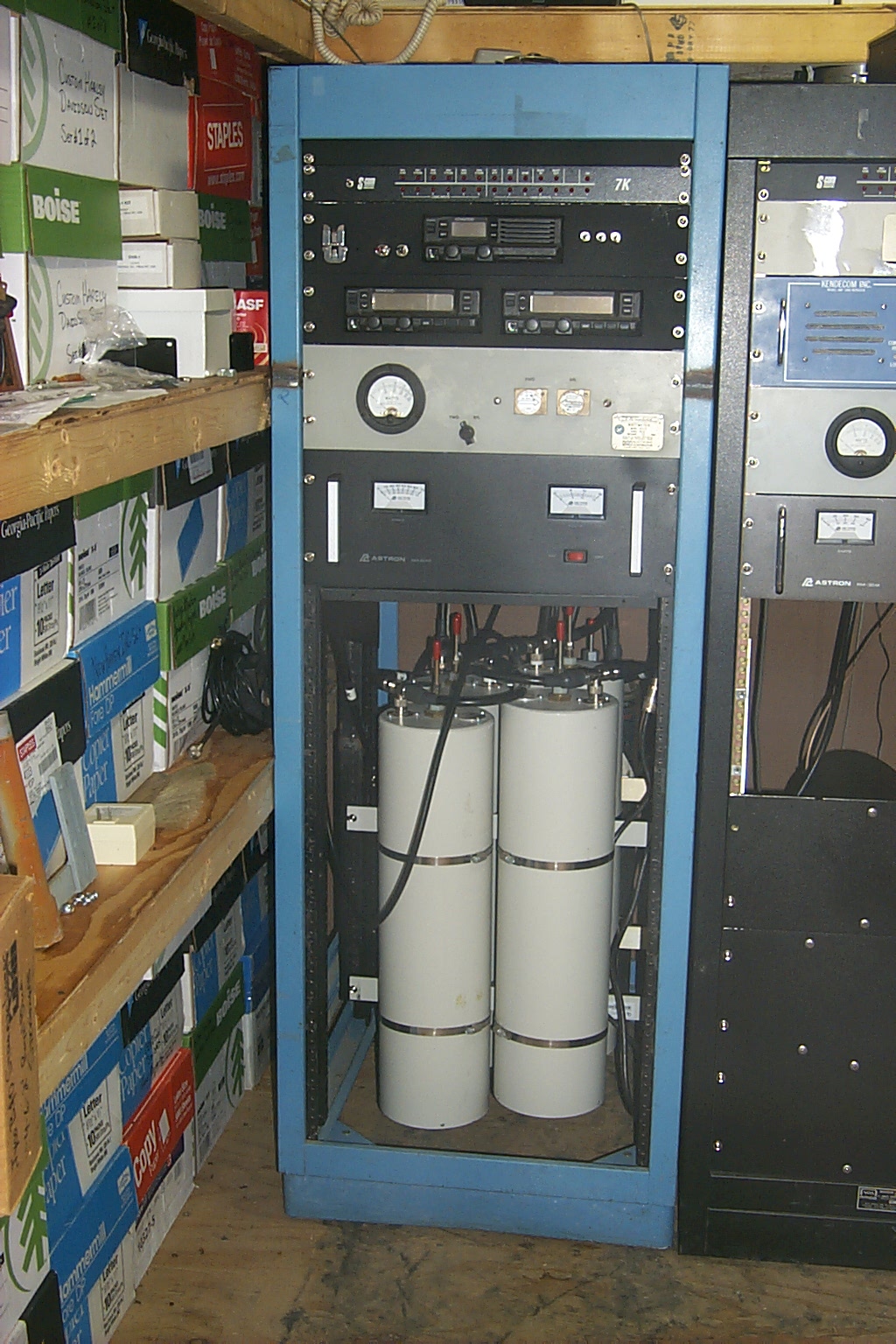
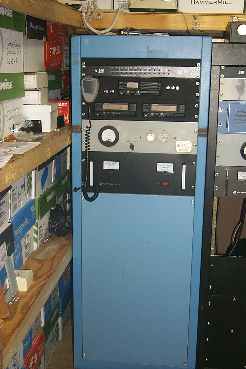
(click on images to enlarge)
More fun coming this spring when we replace the hard-line and antenna...
Update November 16th 2010 - New Antenna
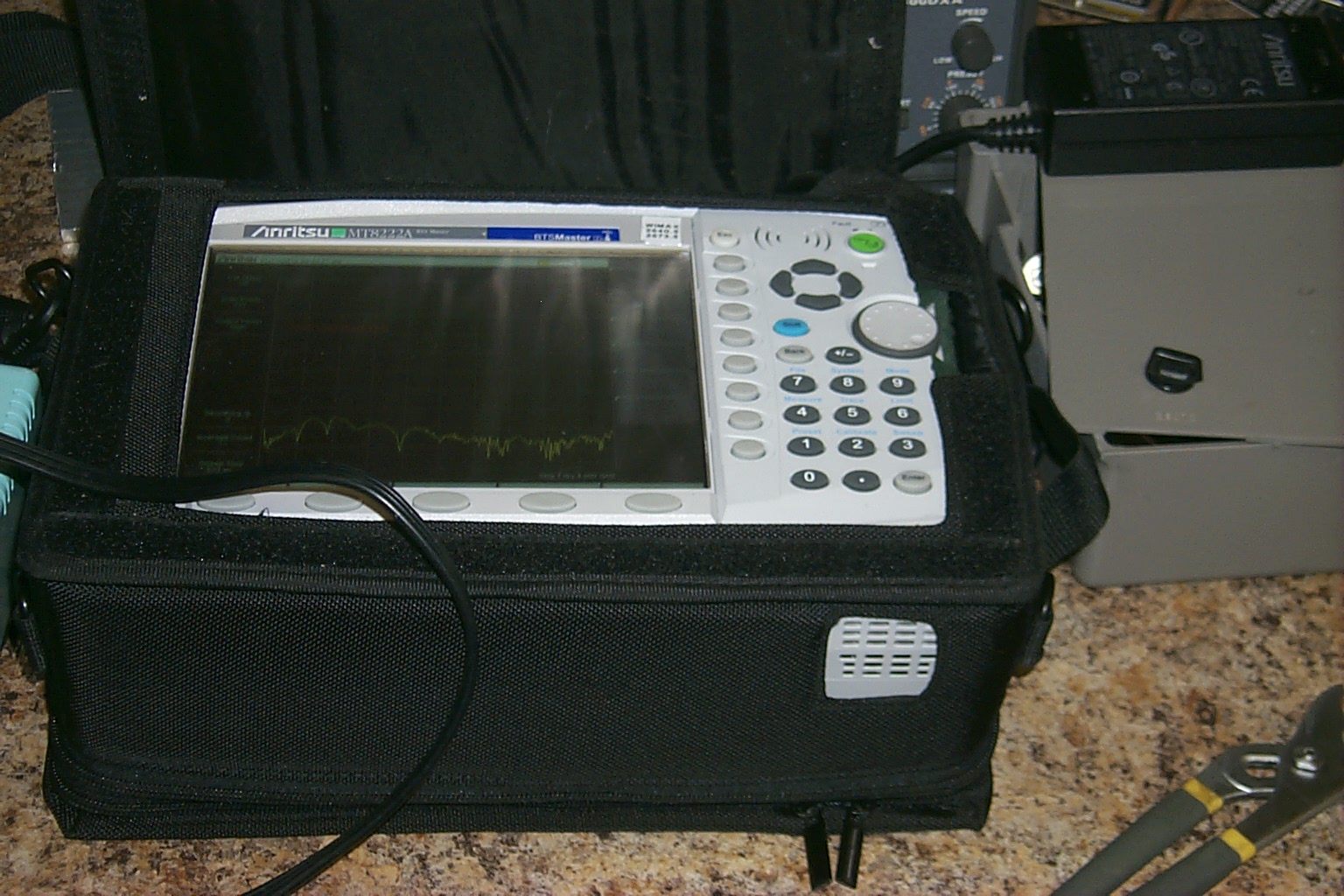
The repeater tower was cranked back up on October 30th, and we have slowly been finishing up all the work at the bottom of the tower to terminate all the hard-line and move the repeaters from the temporary antennas over to the new antennas on the tower. The Lincoln 146.460 repeater was moved to the new G7-144 on Tuesday evening Nov 16th and the initial testing has been good.
Here is the set of numbers from the VSWR sweep done on Monday November 15th
2010 @ side mounted at 55 feet on the tower and weather proofed.
|
FREQ |
Watts Fwd |
Watts Rev |
VSWR |
|
143.50 |
40 |
4 |
1.92 |
|
144.00 |
75 |
5.6 |
1.75 |
|
144.50 |
75 |
5 |
1.70 |
|
145.00 |
80 |
4.2 |
1.59 |
|
145.50 |
86 |
3.8 |
1.53 |
|
146.00 |
92 |
2.8 |
1.42 |
|
146.50 |
90 |
1.2 |
1.26 |
|
147.00 |
90 |
0.56 |
1.17 |
|
147.50 |
90 |
1.3 |
1.27 |
|
148.00 |
92 |
3.2 |
1.46 |
|
148.50 |
92 |
6 |
1.69 |
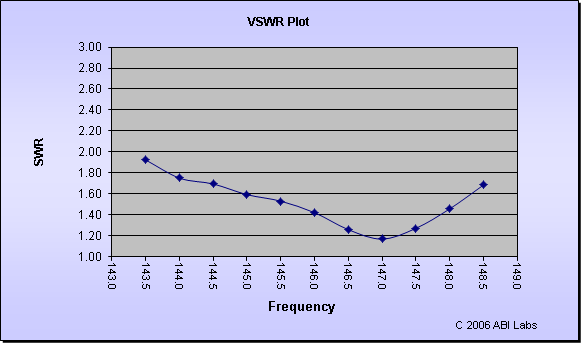
We moved the antenna from the top of the tower where the 146.460 repeater has been the past 18 years 30 feet lower and side mounted it on the south side of the tower in an attempt to reduce the signal strength to the north.
(click on image to enlarge)
On Thursday afternoon Nov 18th I was able to terminate the run of FSJ4-50B for the UHF link antenna and get the repeater back on the network.
Update August 18th 2014 - New input frequency
To better align with the NESMC band plan the input frquency has been moved to 144.960 MHz.
Return to the KA1RCI Repeater Network Home Page
This page was last updated on 08/18/2014
Send mail to [email protected] with questions or comments about this web site.
Copyright 1995-2014 Steven M Hodell
Copyright in these pages, in the screens displaying the pages and in the information, materials and other content contained in this web site is owned by Steven M Hodell unless other wise indicated and is protected by U.S. and international copyright laws and treaties. The information, materials and other content of this web site may not be copied, displayed, distributed, downloaded, licensed, modified, published, reposted, reproduced, reused, sold, transmitted, used to create a derivative work, or otherwise used for public or commercial purposes without express written consent.