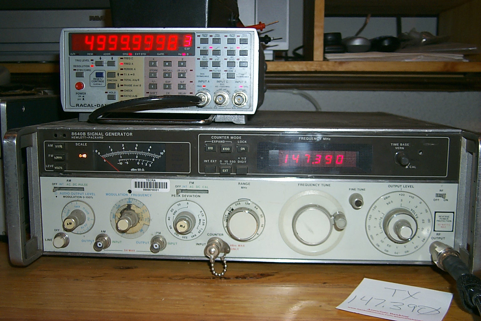
147.390 / 147.990 with PL 67.0 Established 2005
Westerly - Rhode Island
With the success of the 147.075 build using commercial Kenwood TK-30 series radios I decided to build a new repeater for the Westerly site following the same model while using the lessons learned on the .075 build to complete the new 147.390 repeater.
The scavenger hunt begins...
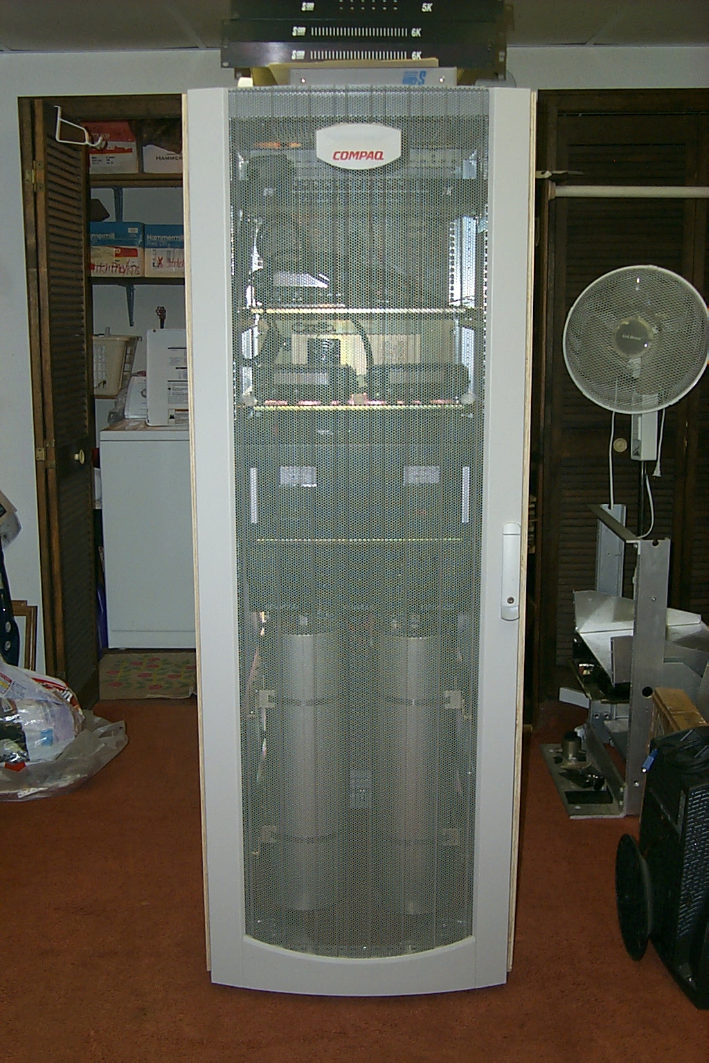
I already had a supply of the surplus Kenwood radios, an extra S-Com 7K controller, and a very nice equipment rack so I was already well on my way. I stumbled across a set of Sinclair VHF cavities that had just been pulled from a high power VHF repeater on 150 MHz and was able to purchase them at a reasonable price.
(click on images to enlarge)
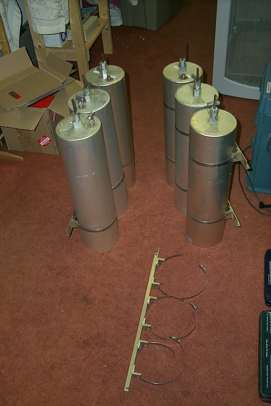
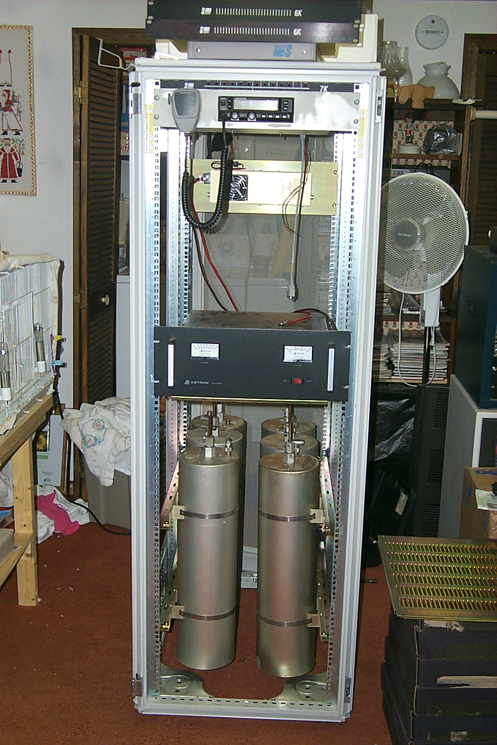
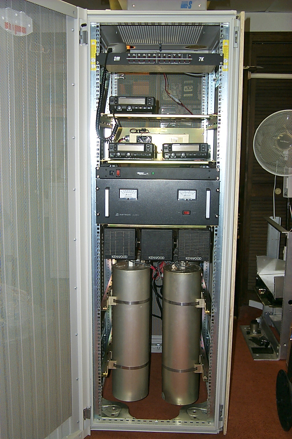
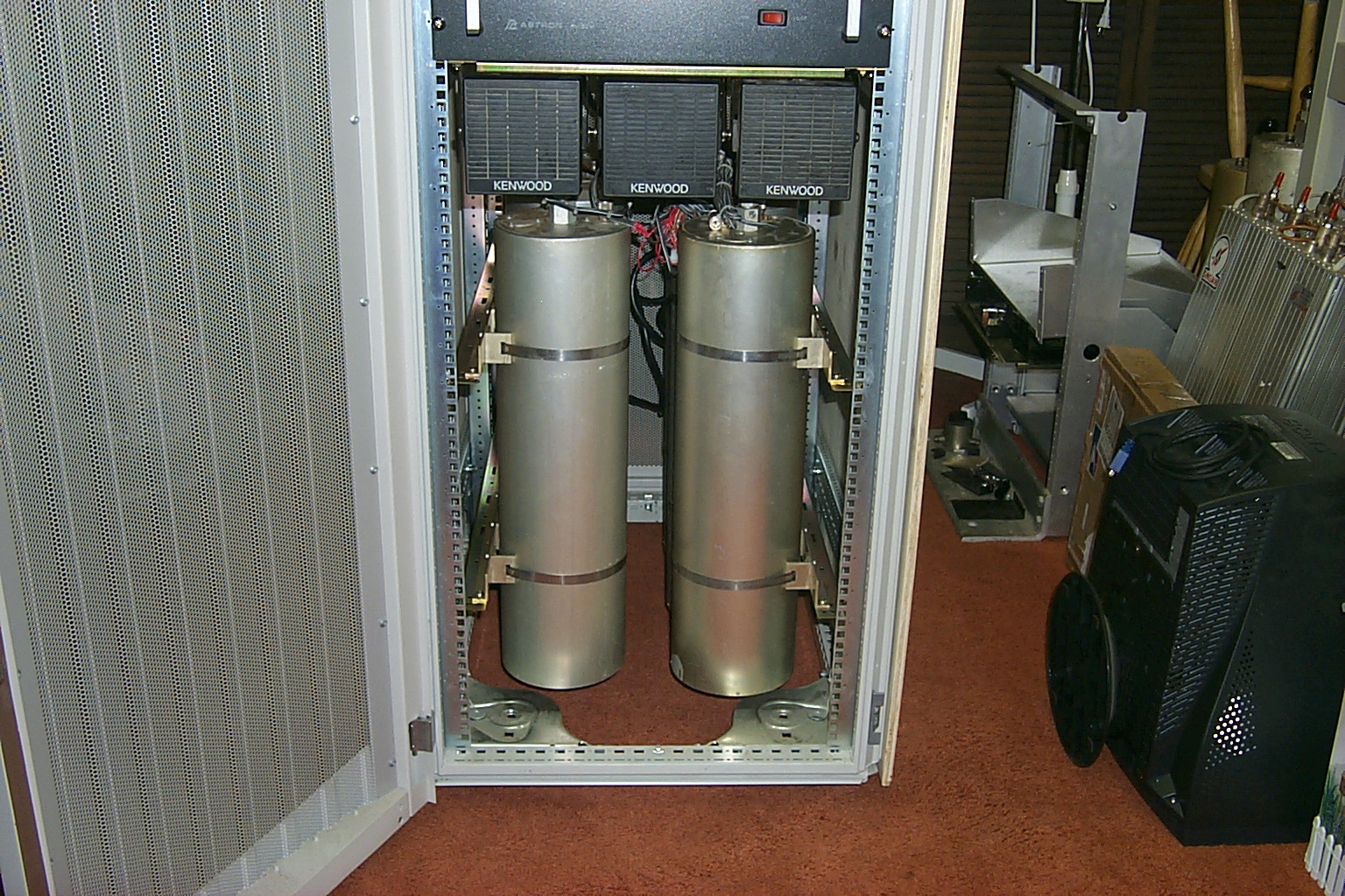
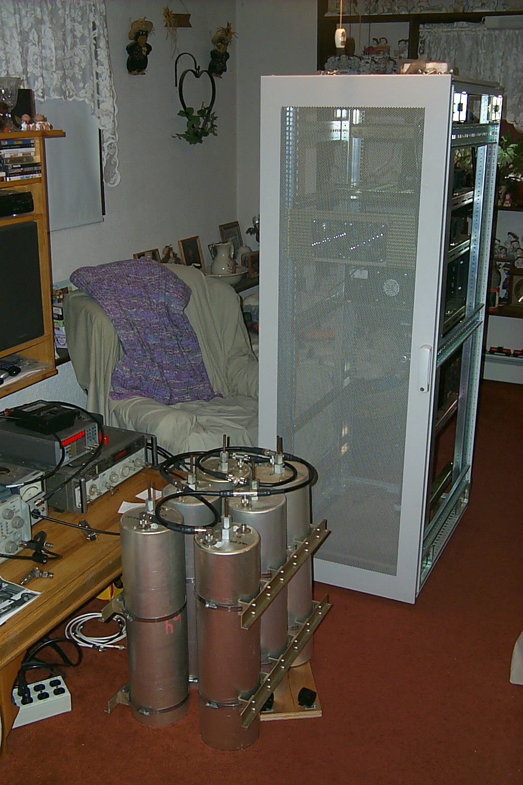
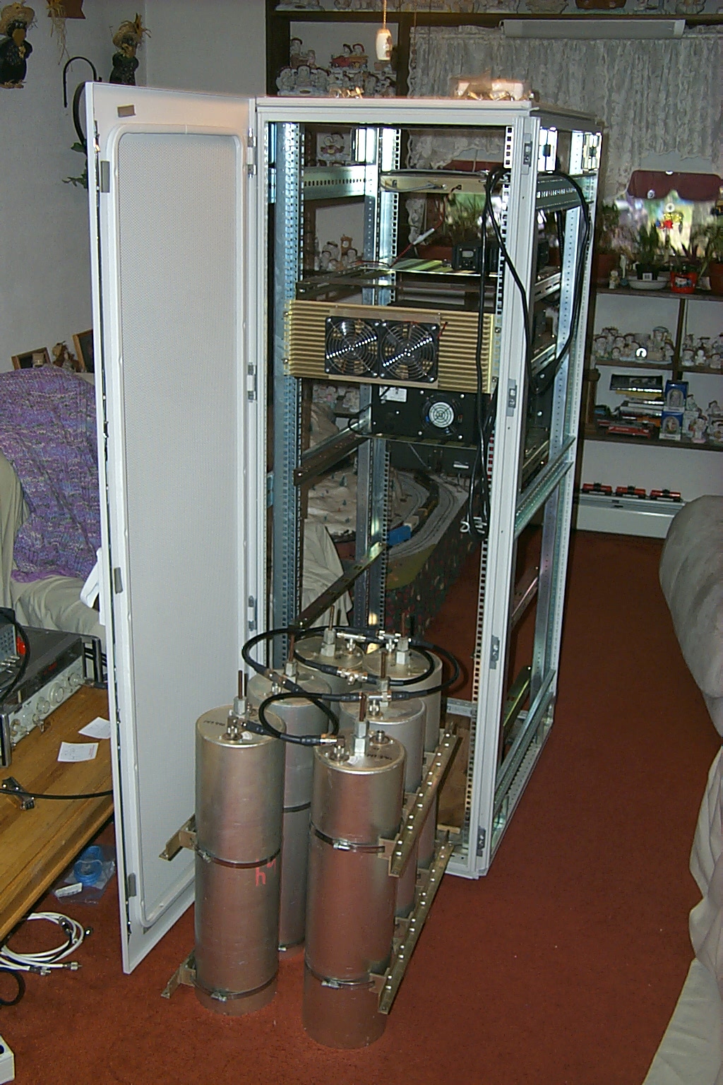
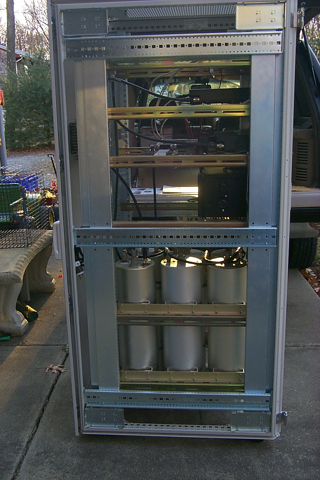
The factory 150 to 174 MHz phasing cable was in poor shape and the cavities were covered in gunk but I was able to clean them up and get the cans tuned on the 147.390 / 147.990 frequency pair. I just had the duplexer sitting in the bottom of the rack on a piece of plywood because there was no mounting hardware but it was working.
In just a few weeks I had the repeater on the air and it was working fairly well.
How do I mount this duplexer?
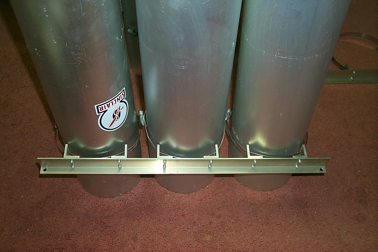
The cavities did not come with any mounting hardware so I had to shop around and was able to purchase a used set of the correct rack mount brackets. Jag from J&A Antenna Filter Systems, who has provided most of the duplexer hardware used on my repeater network, had just the right hardware that I needed to mount these six cavities in my rack.
(click on images to enlarge)
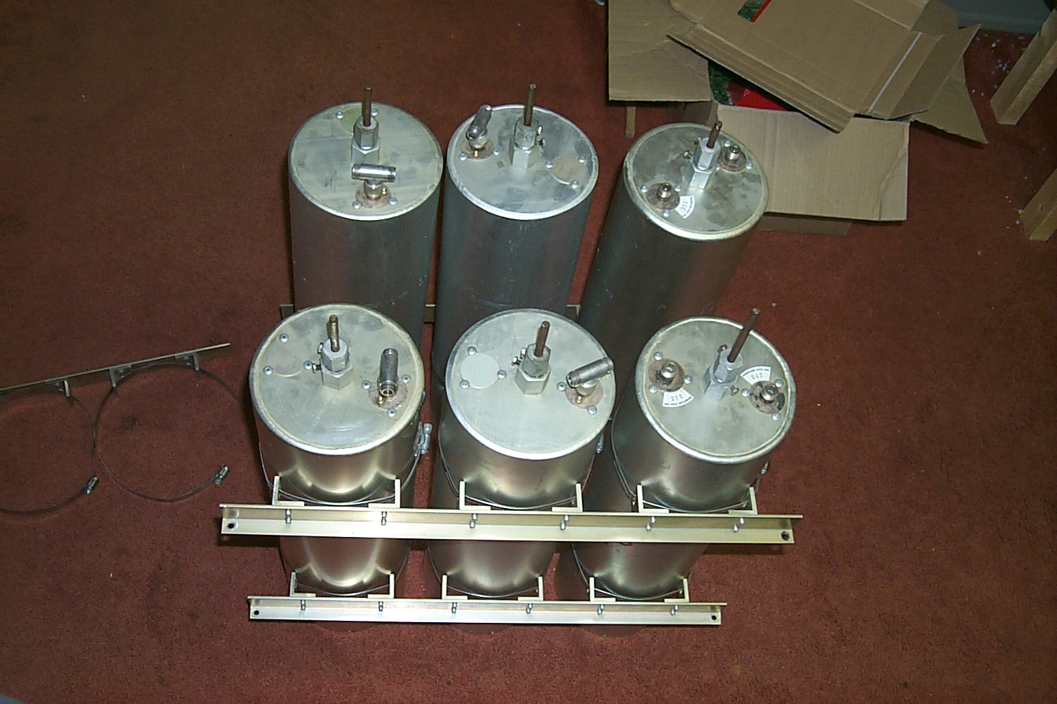
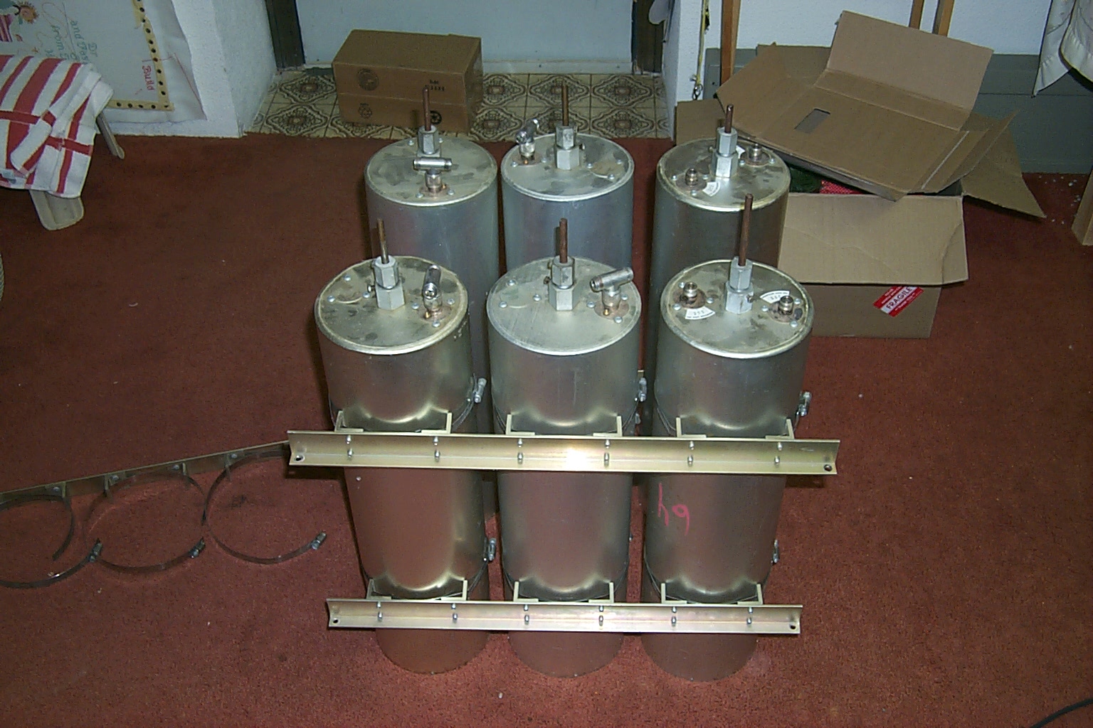
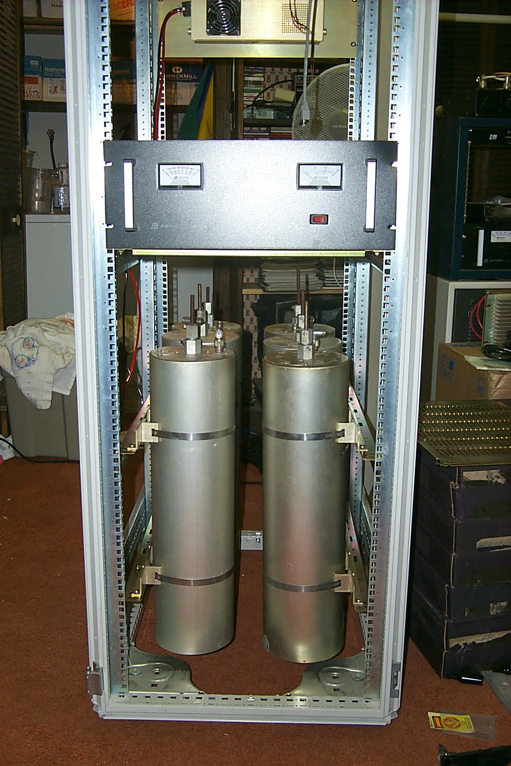
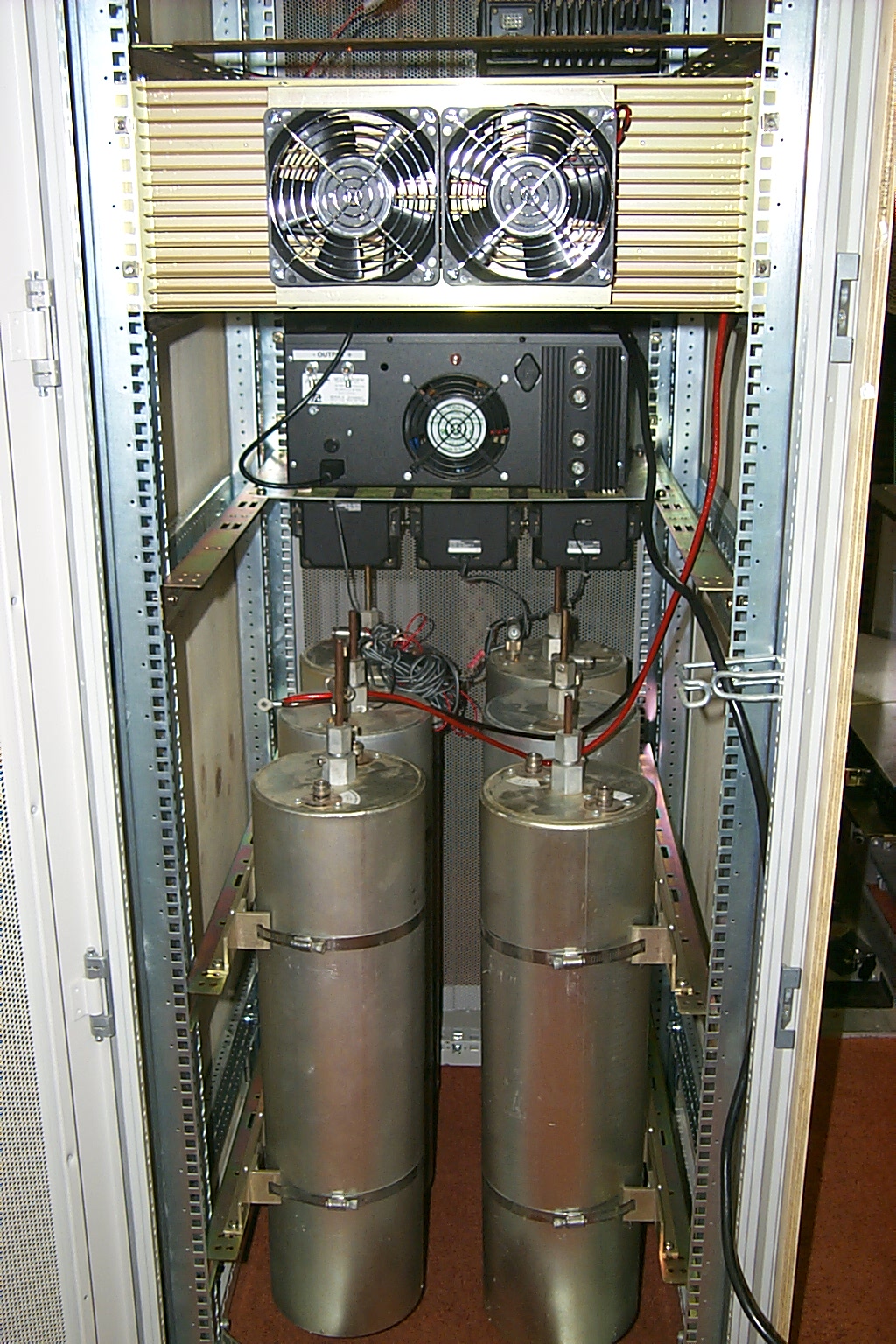
Mounting the cavities in the rack
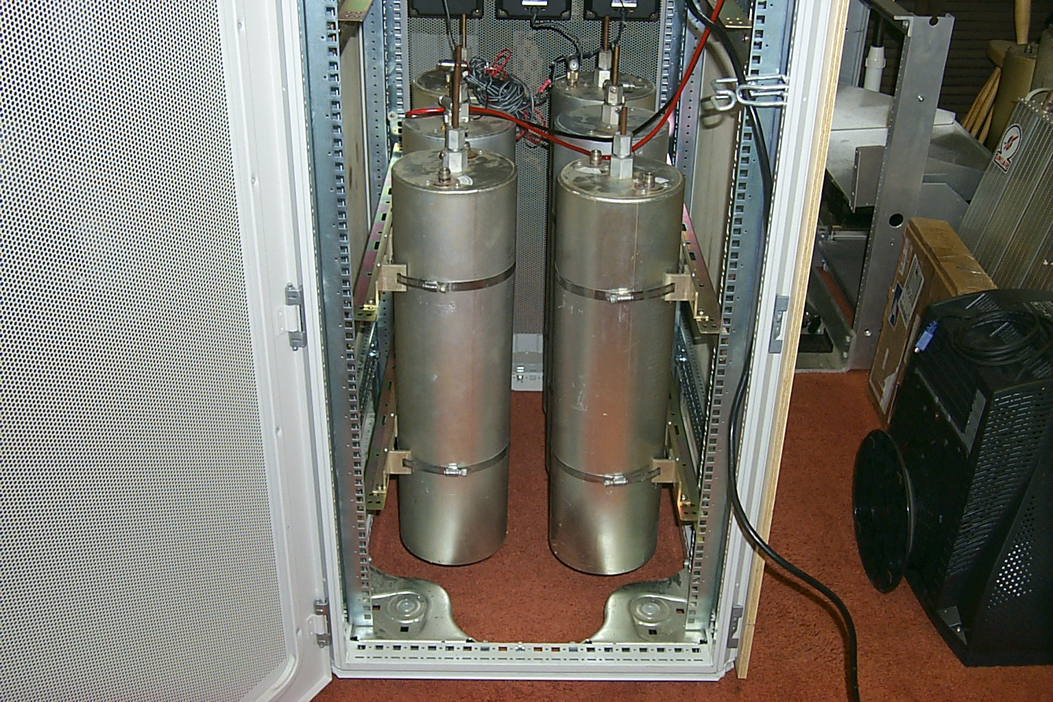
Now that I had the correct mounting hardware from Jag I was able to fabricate rails that would bolt into the rack cabinet and provide a mounting point for the duplexer. (I could get rid of that piece of plywood too) These rails allowed me to float the cavities in the bottom of the cabinet, it also let me adjust the position of the cavities up and down staggering the height of the cavities so the phasing harness would fit better.
(click on images to enlarge)
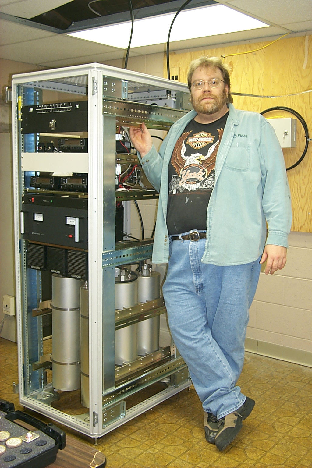
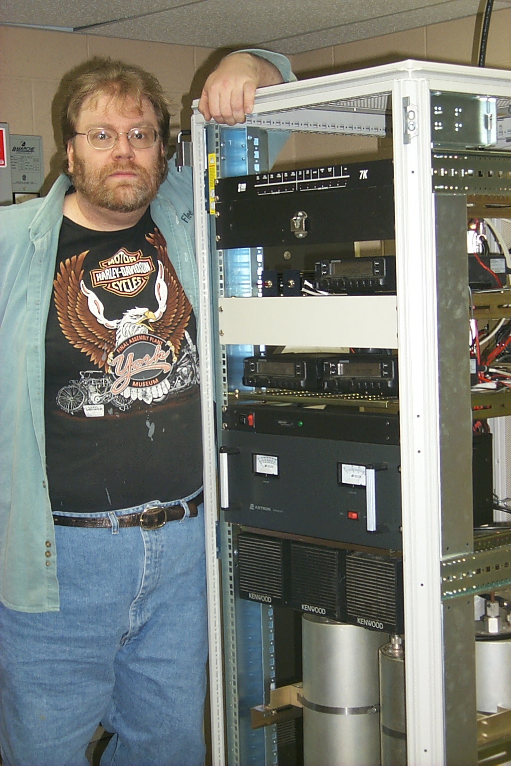
Planning the hardware placement
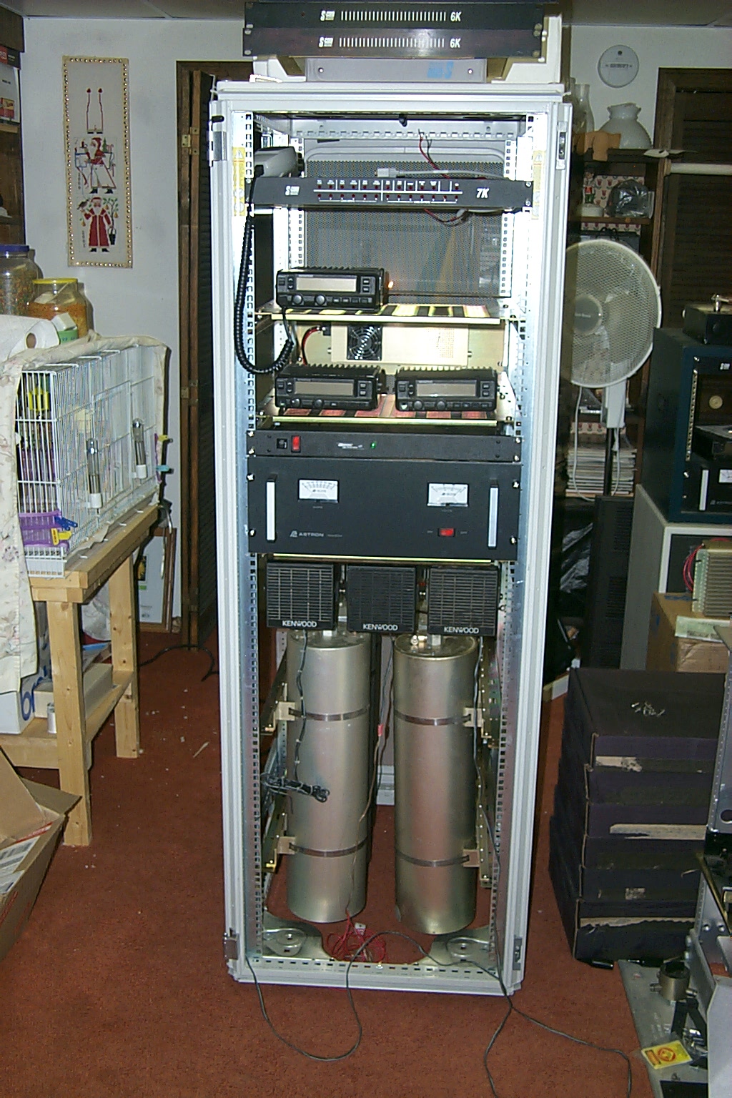
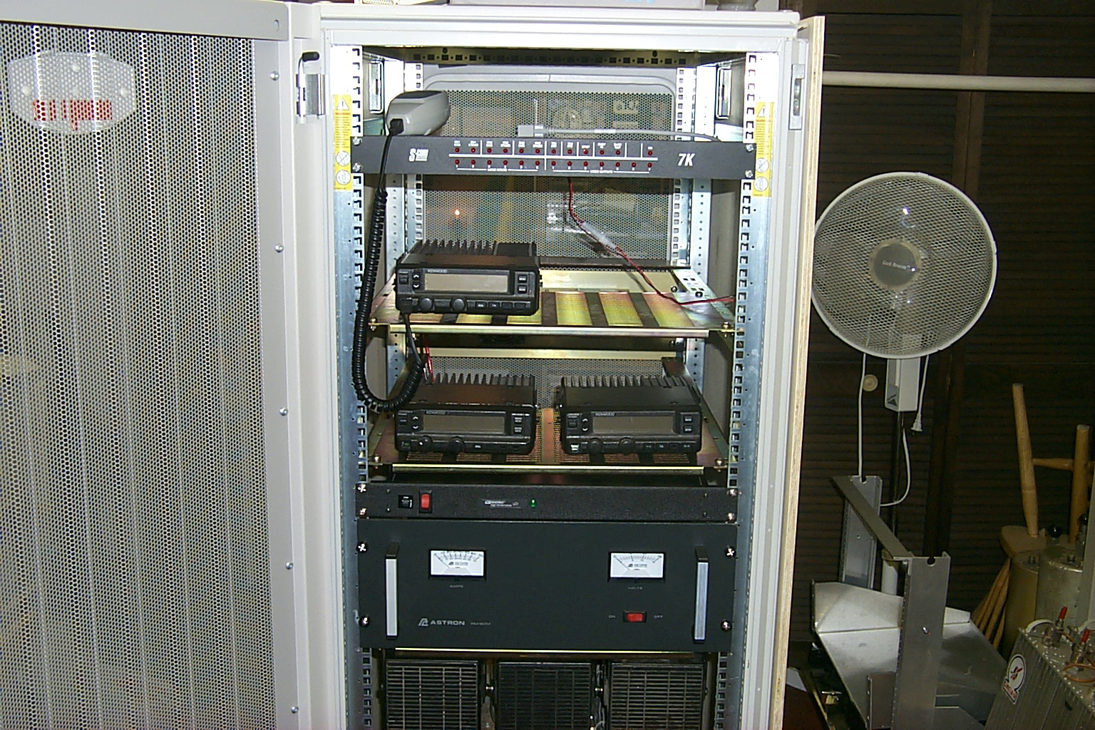
For the first year all of the 147.390 repeater hardware was just sitting loose in the rack cabinet, nothing was bolted down and all the cabling was just temporary. I had been planning on mounting the radios in the rack using some of the custom brackets that my brother-in-law made however once I saw how nice these adjustable rails worked on the duplexer mounts I switched gears. I send Sandy over to her brothers with a bunch of the standard rack shelves that fit these rails and had him cut them down to the correct size for the Kenwood TK-30 series radios and the Astron power supply.
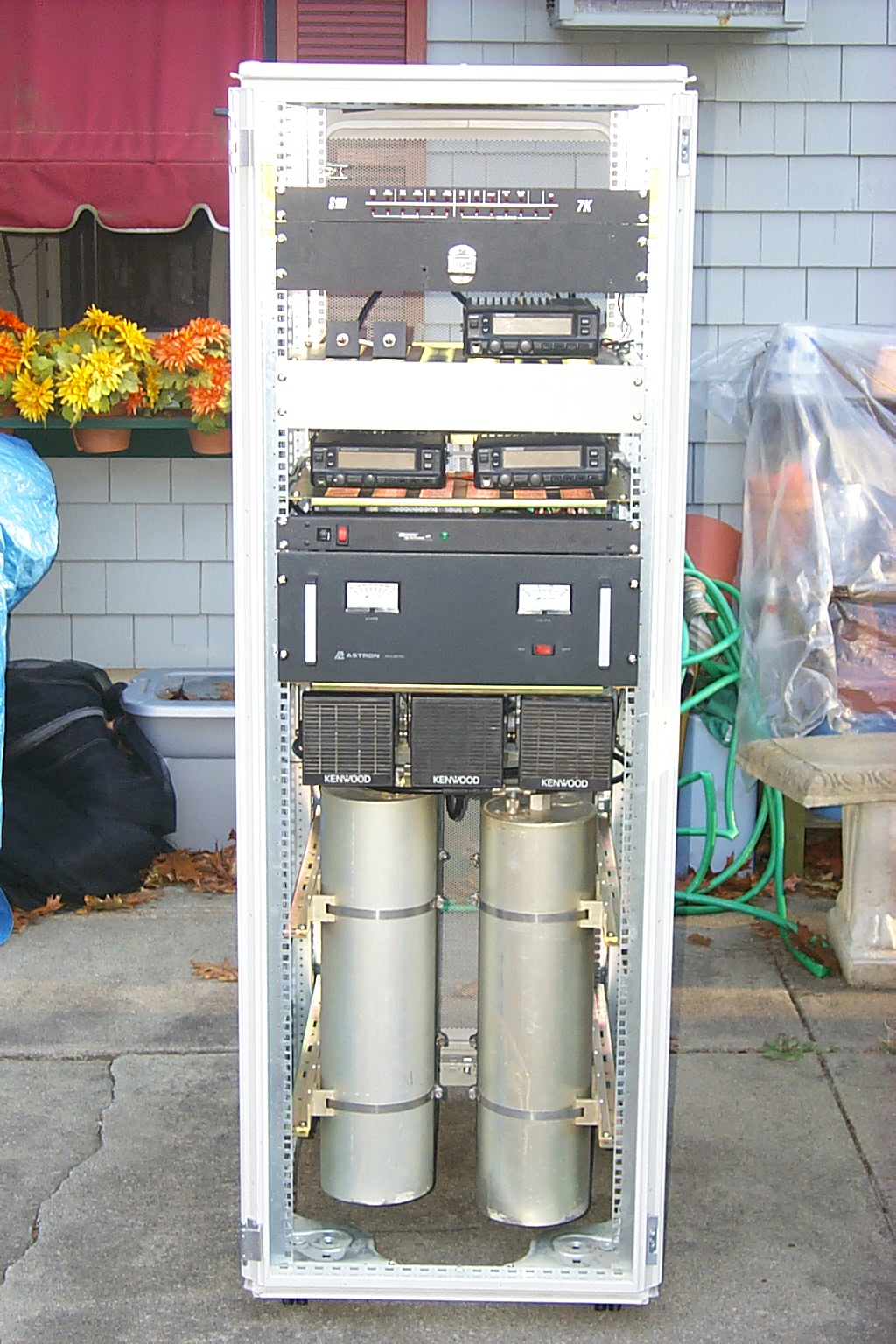
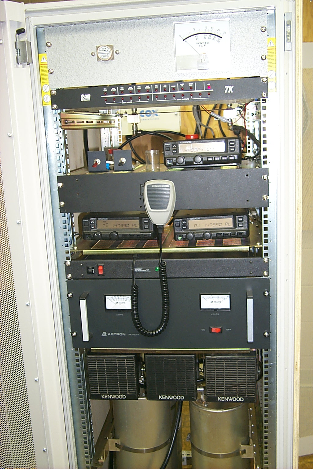
Then the rest was very easy mounting the rails, shelves, and bolting the radios into the cabinet.
(click on images to enlarge)
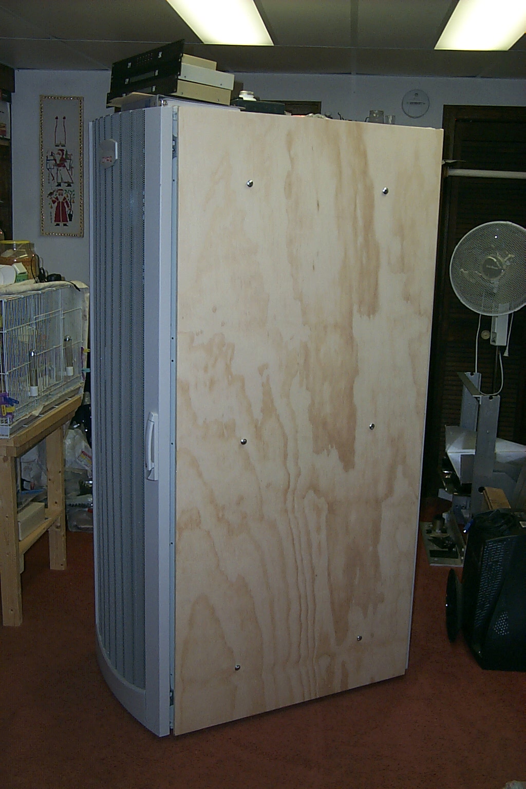
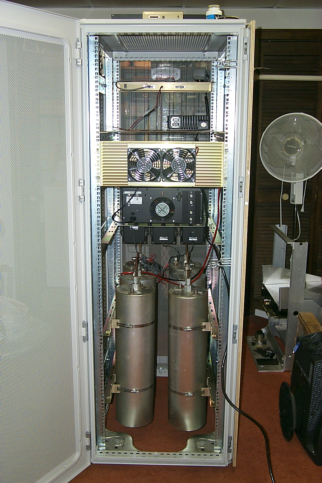
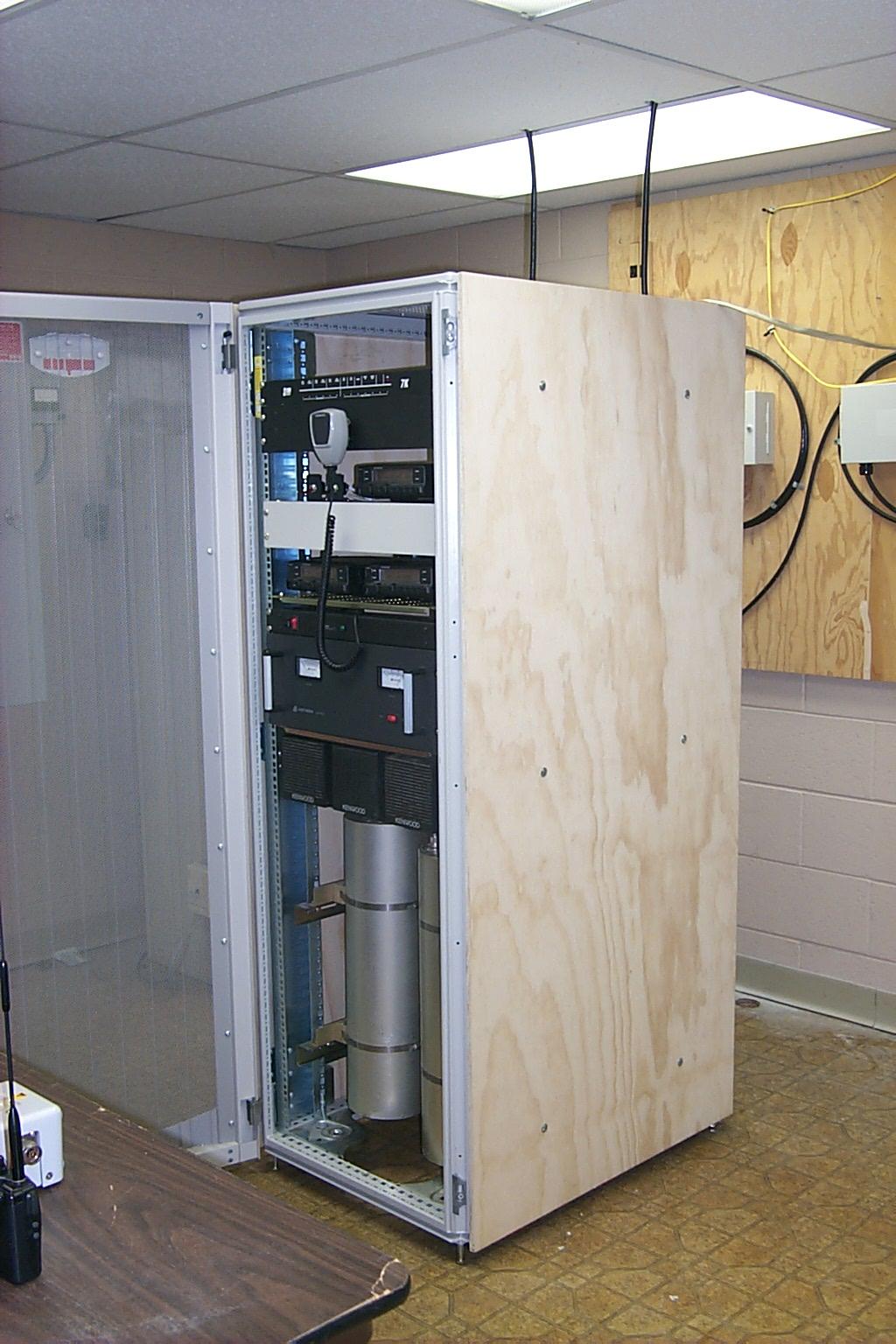
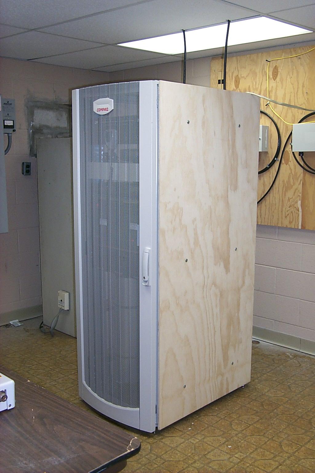
When I rescued this rack cabinet from the land fill it was missing the side covers so Bruce KD1BE once again stepped up and made two very nice plywood panels that I could bolt to the rack keeping all the hardware inside safe and clean.
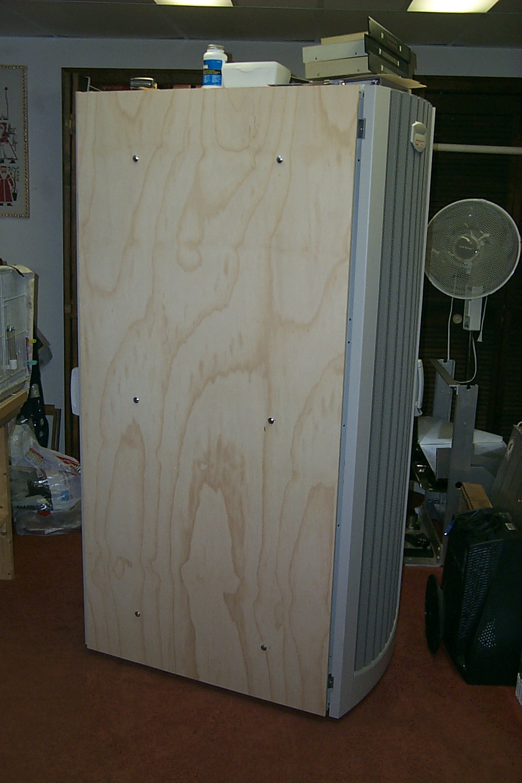
(click on images to enlarge)
WIRES WIRES WIRES
With all the hardware bolted into the rack I could finally toss all the temporary wires and cables that had been controlling the repeater and make all new permanent cables.
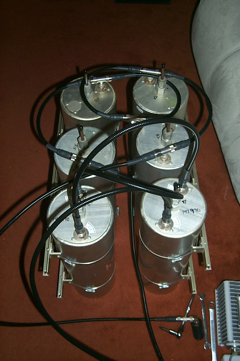
Time for a new phasing harness
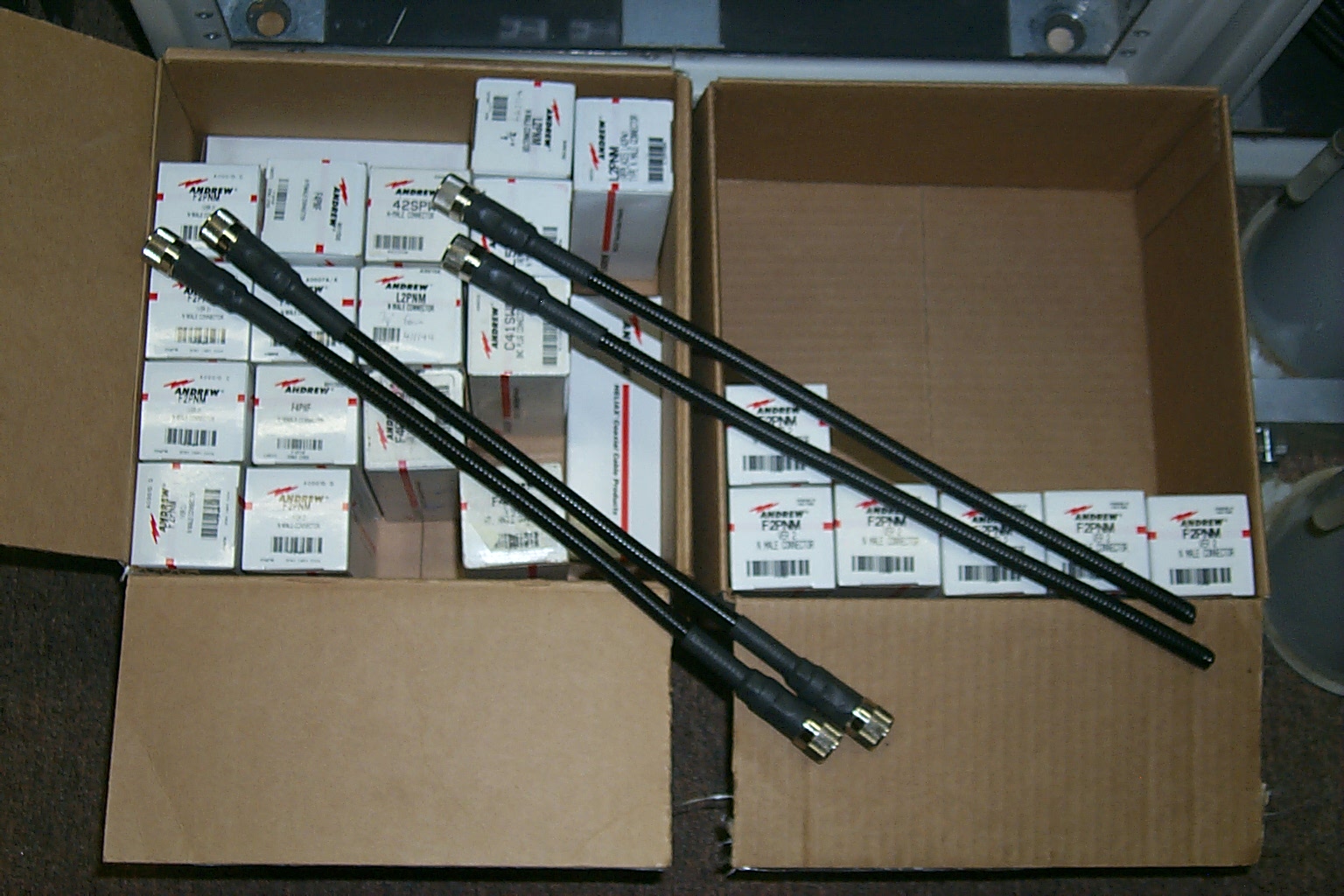
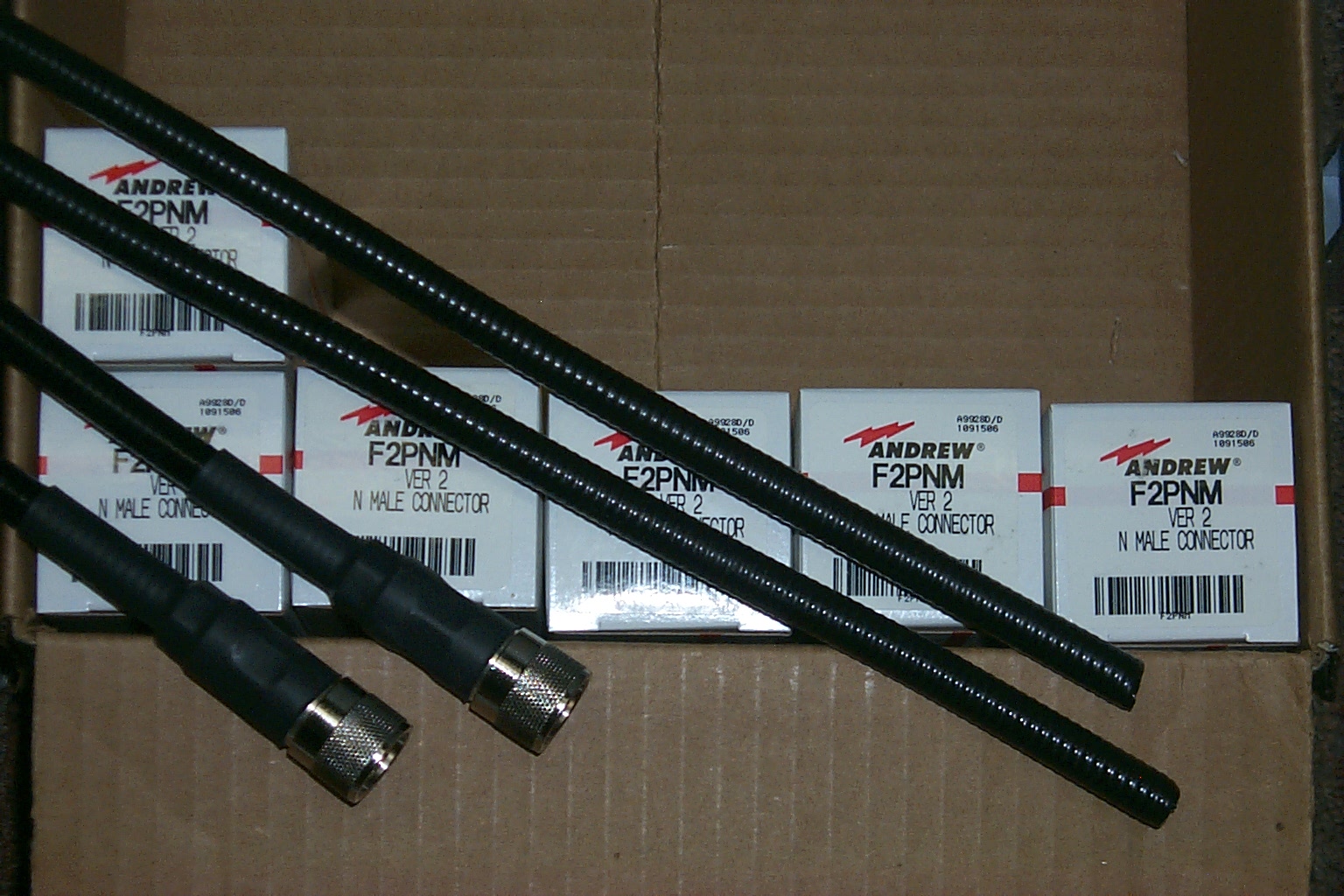
After struggling with the factory Sinclair cable I decided to scrap it altogether and build a completely new phasing harness using new Andrew FSJ-2 superflex hard-line, Type-N connectors, and Tee adaptors. I was able to purchase everything I needed on eBay from multiple sources. One seller had the FSJ-2 hard-line, another had the connectors, someone else had the Type-N (M-F-F Tee adaptors) another had the (F-F-F Tee) and so on. After a few more weeks of shopping online I was able to acquire all the items that I need to build a new phasing harness.
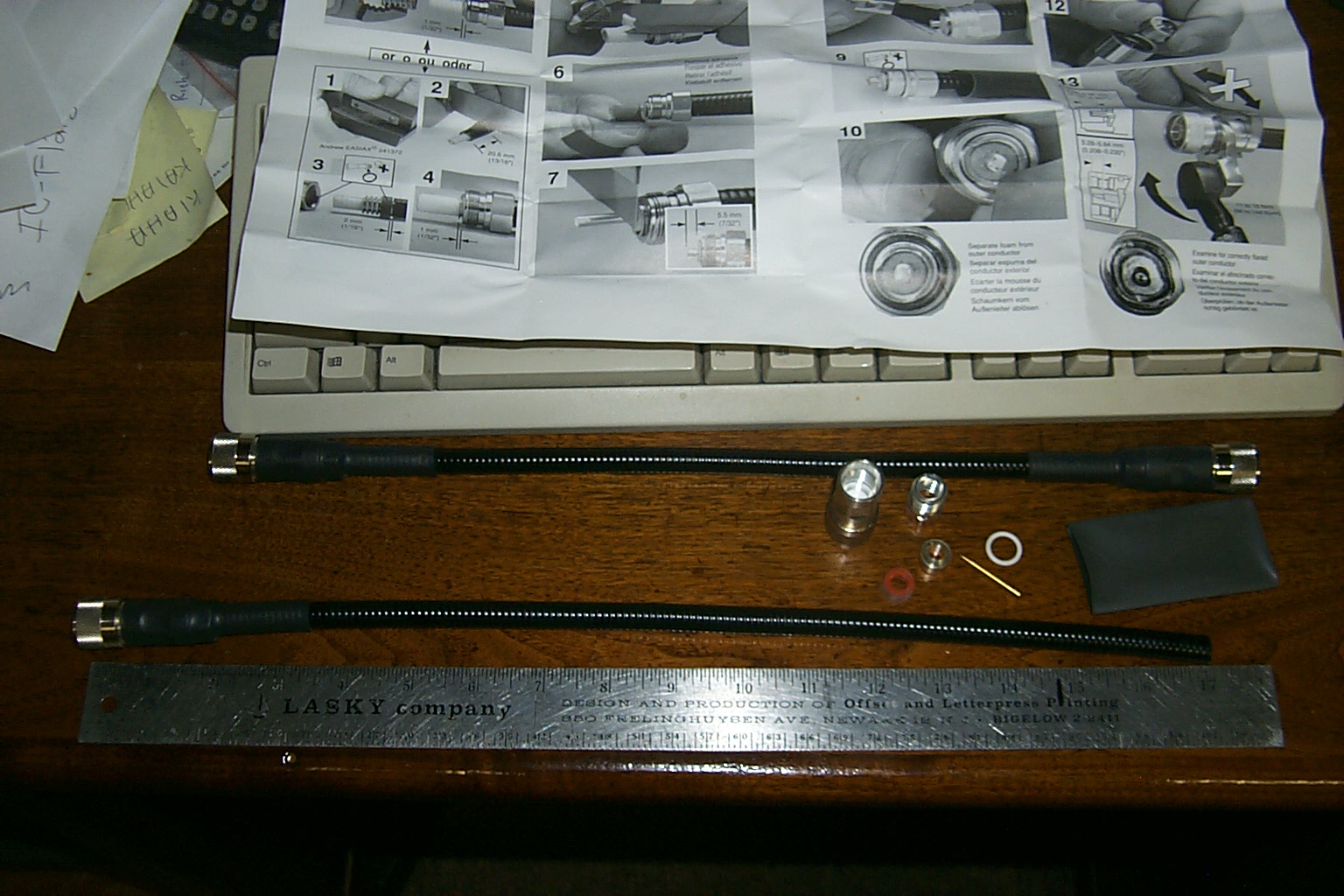
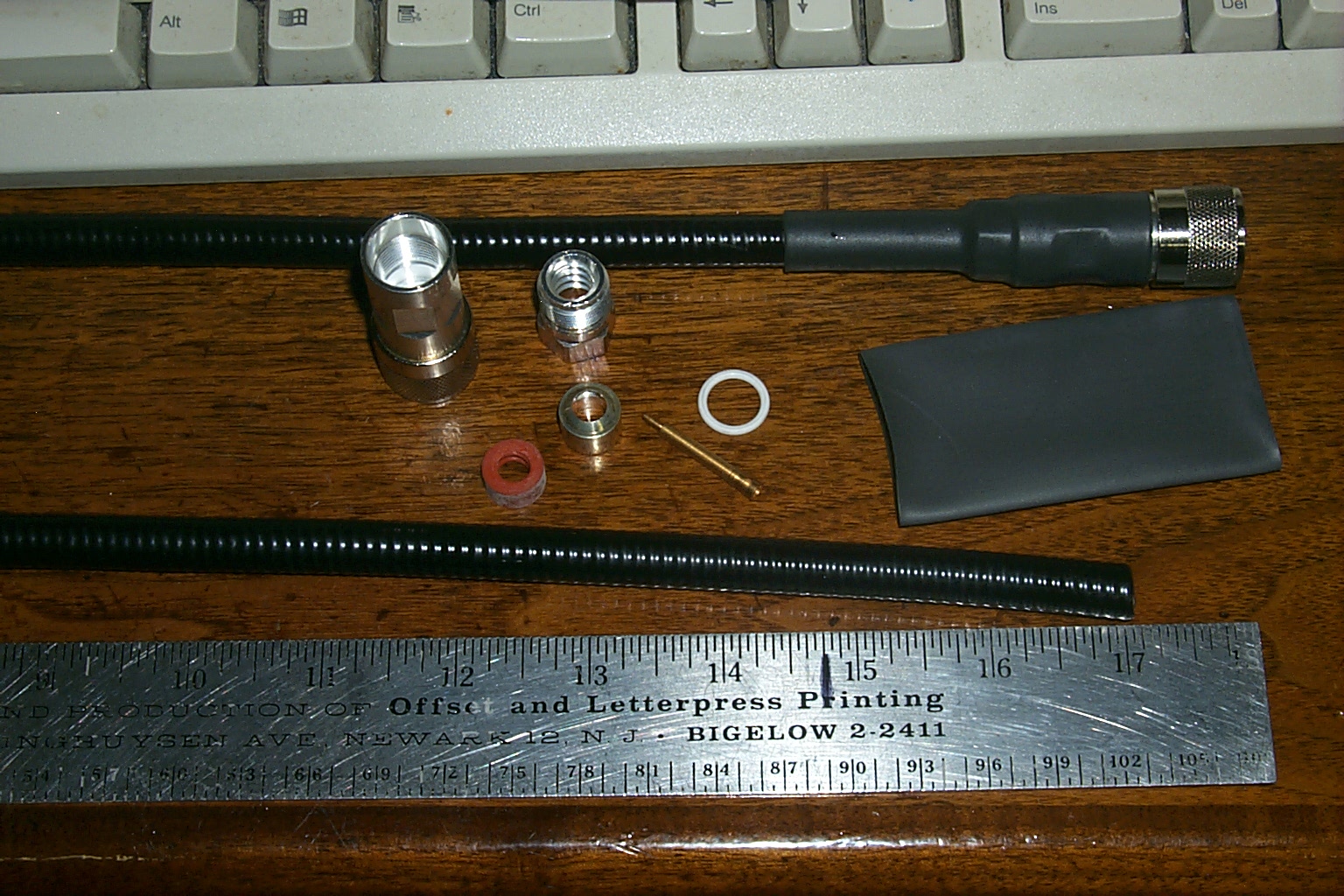
(click on images to enlarge)
I had already done this on the .075 repeater and at that time John WA1ABI had provided me with the velocity factor for the cable, Jag provided me with the information for the Sinclair cavities, and my Dad KA1VKD worked out all the math so that each jumper in the phasing harness could be cut to the proper length.
Once I finally sat down at the bench to make up all the custom cables it took me about nine hours to complete the work.
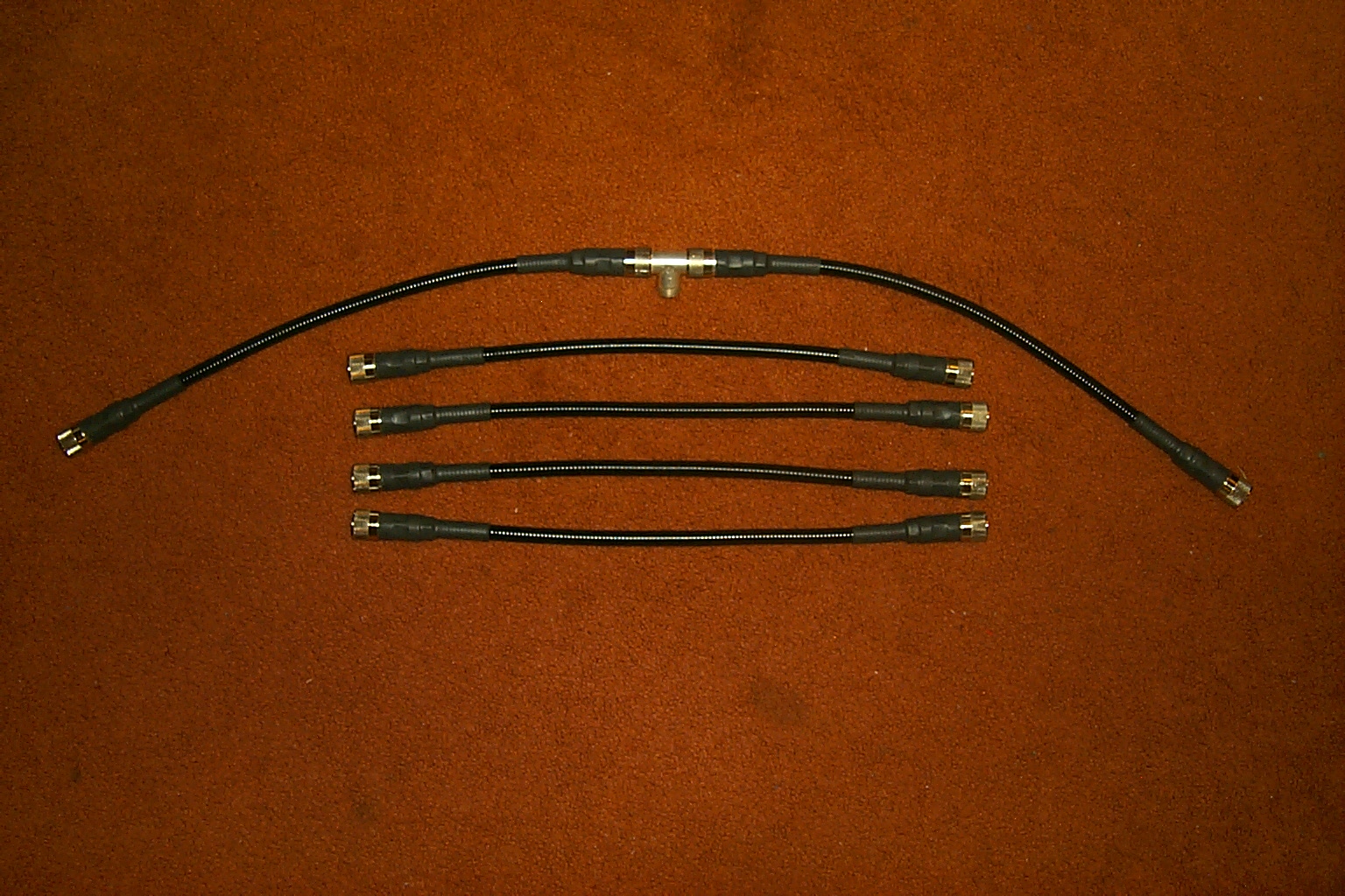
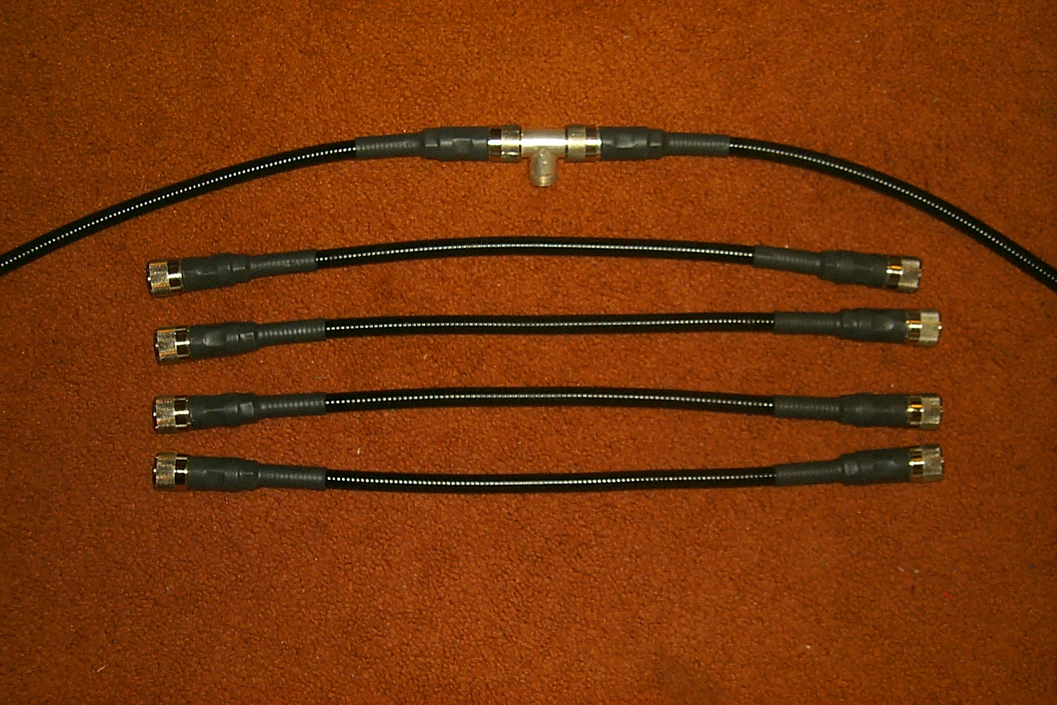
(click on images to enlarge)
I had to re-tune all the cavities once the new
phasing harness was built and the duplexers performance was greatly improved
with the new FSJ-2 hard-line.
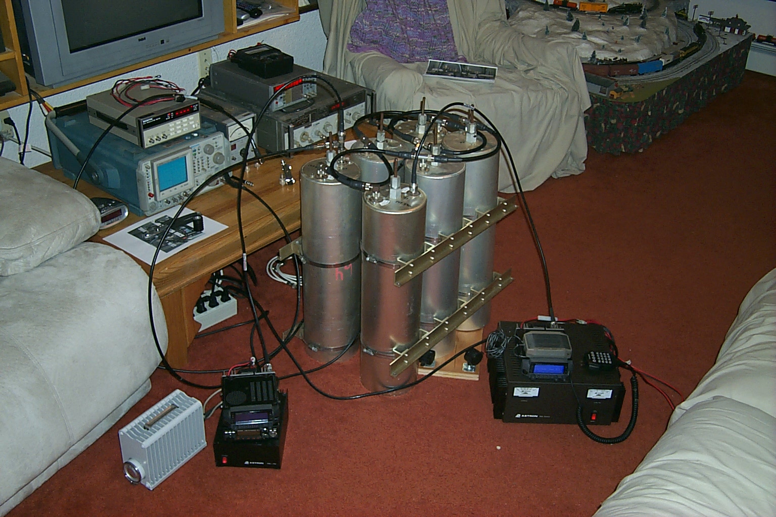
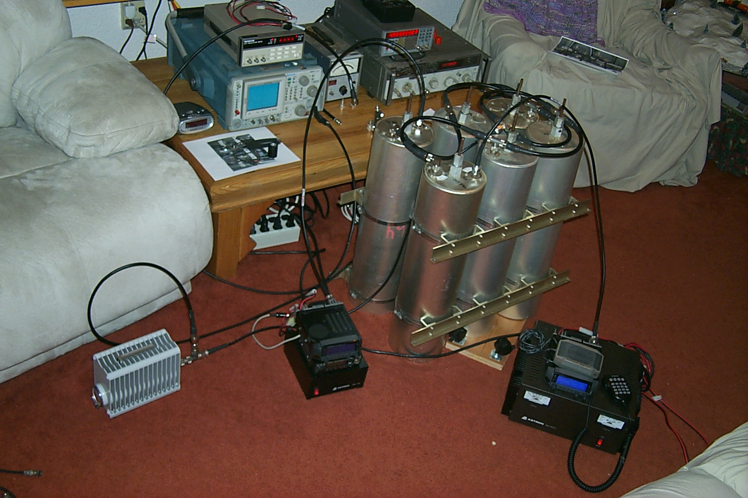
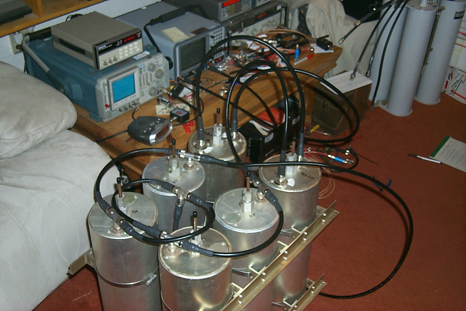
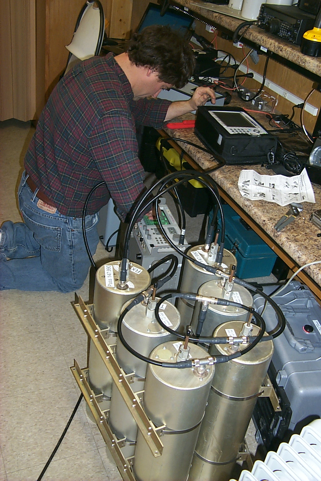
Setup the RF Lab!
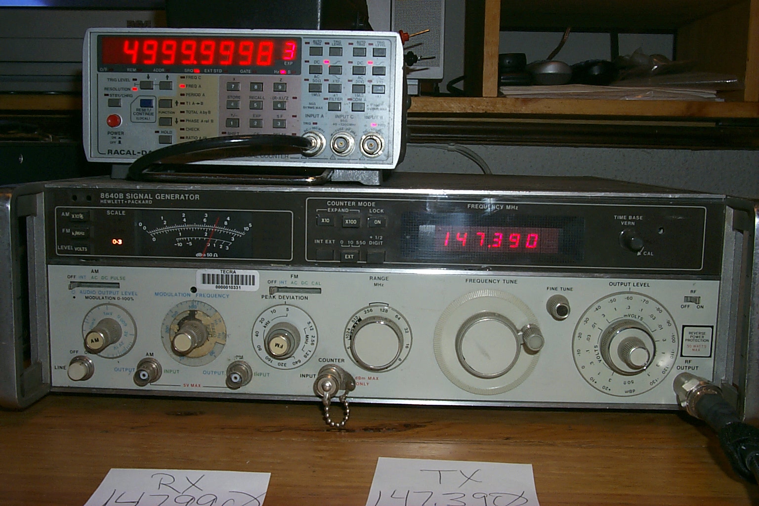
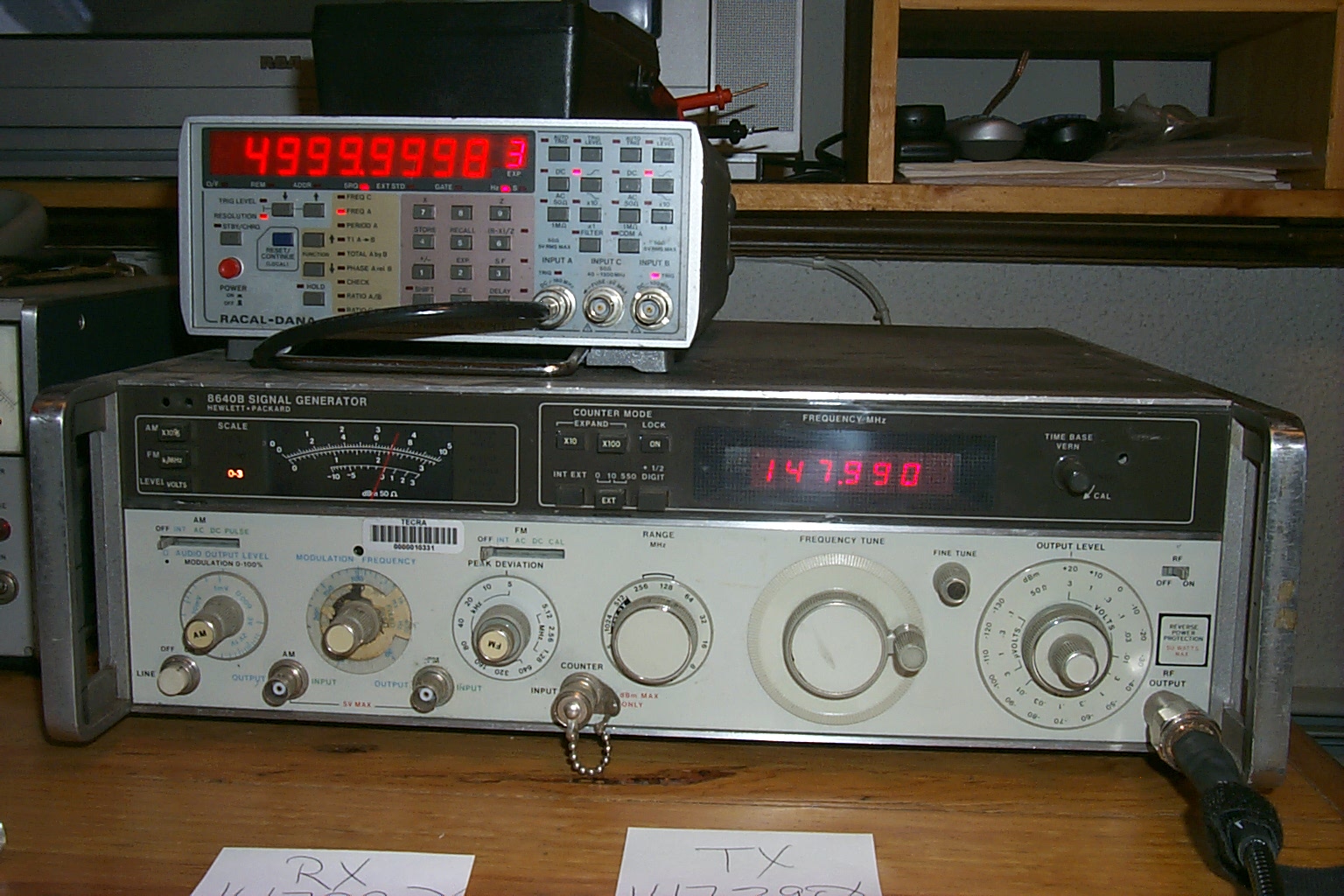
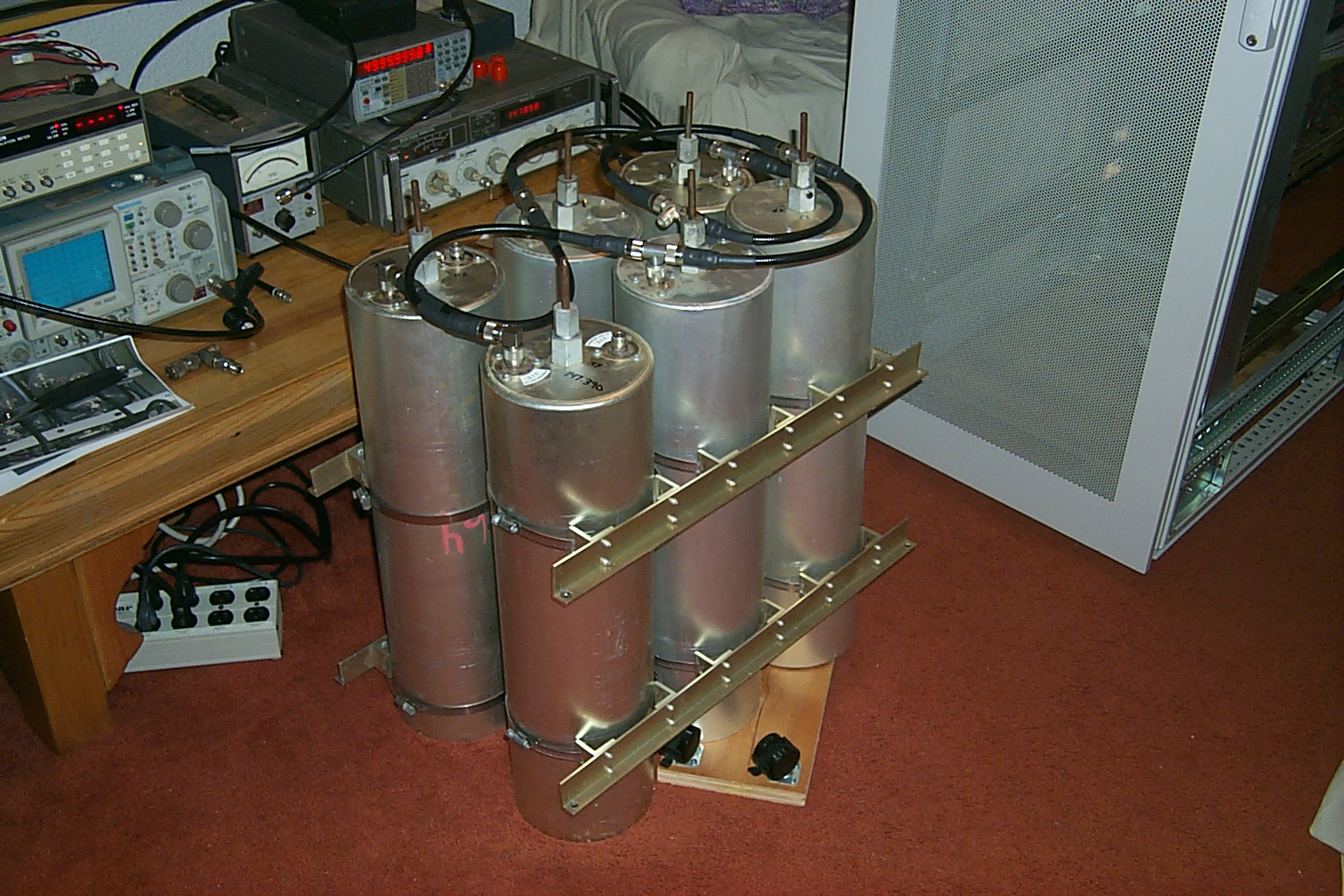
I do not have a proper RF Lab at my QTH so every new repeater build means setting up all the test gear on the coffee table in our living room. This is the point where I explain how understanding Sandy is and just how supportive of all this radio madness she really is... Once all the test gear was setup, and had warmed up a few days, I got started re-tuning the cavities with the new FSJ-2 phasing harness.
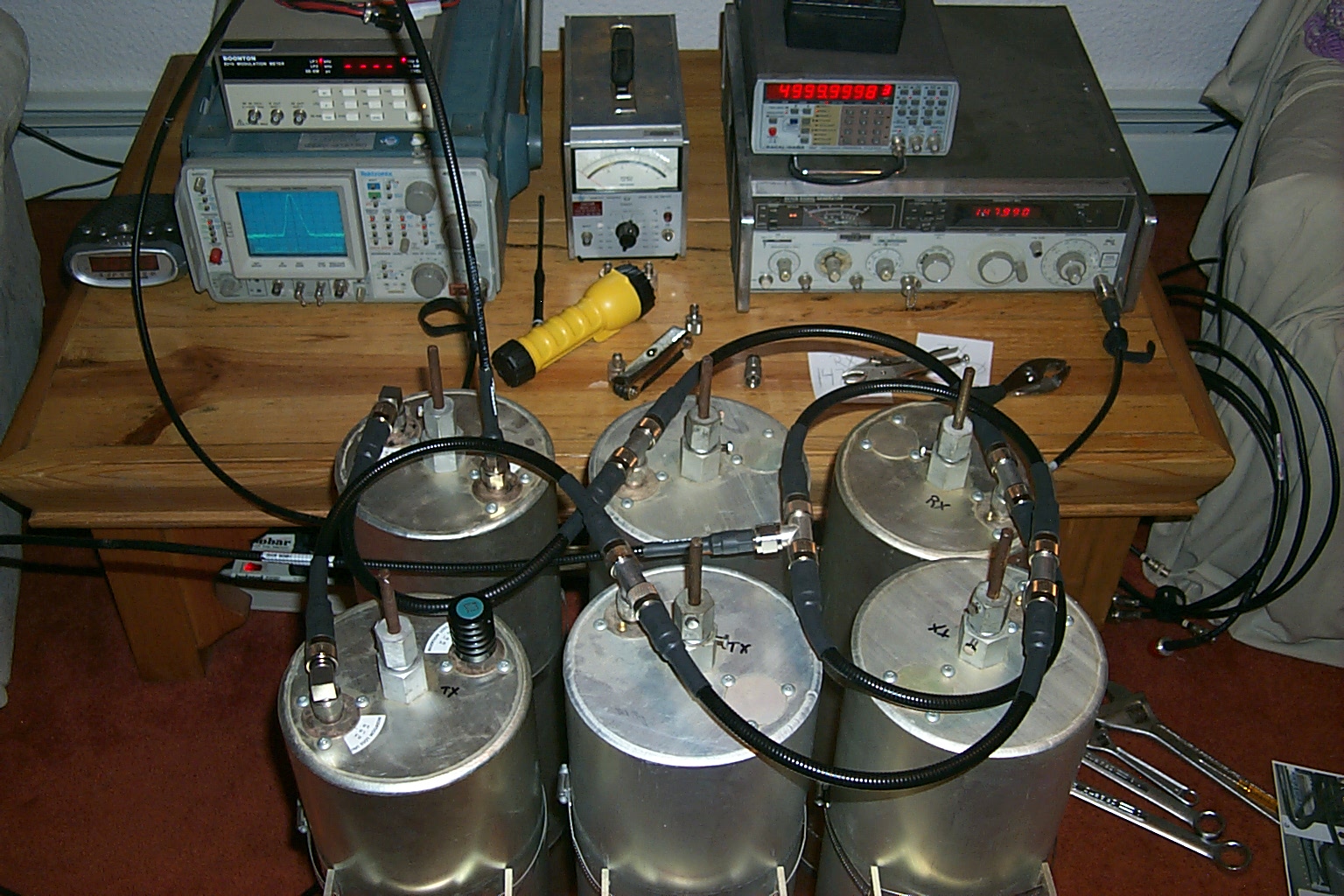
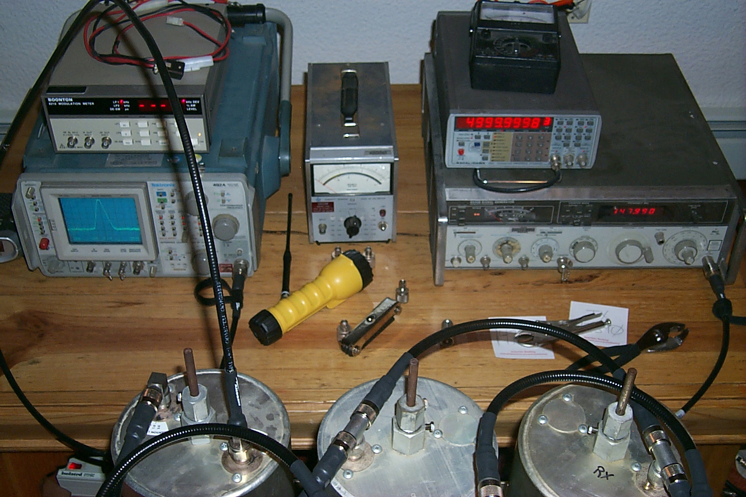
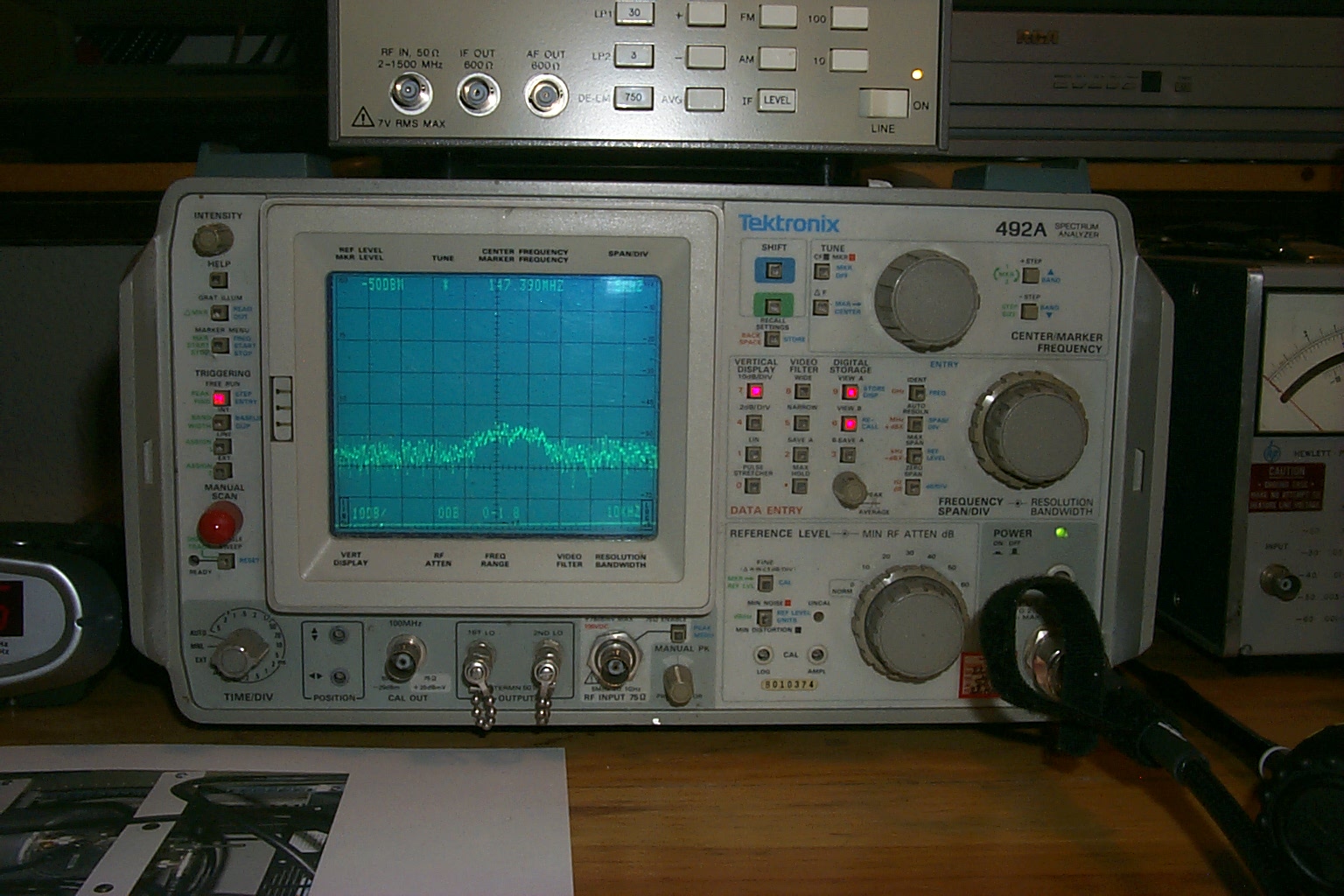
(click on images to enlarge)
Each step of the way John WA1ABI guided me thru the process, answering my questions, helping me get the cavities tuned up correctly.
(click on images to enlarge)
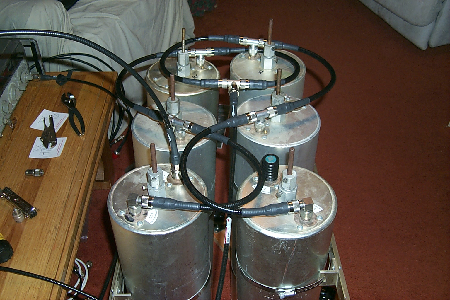
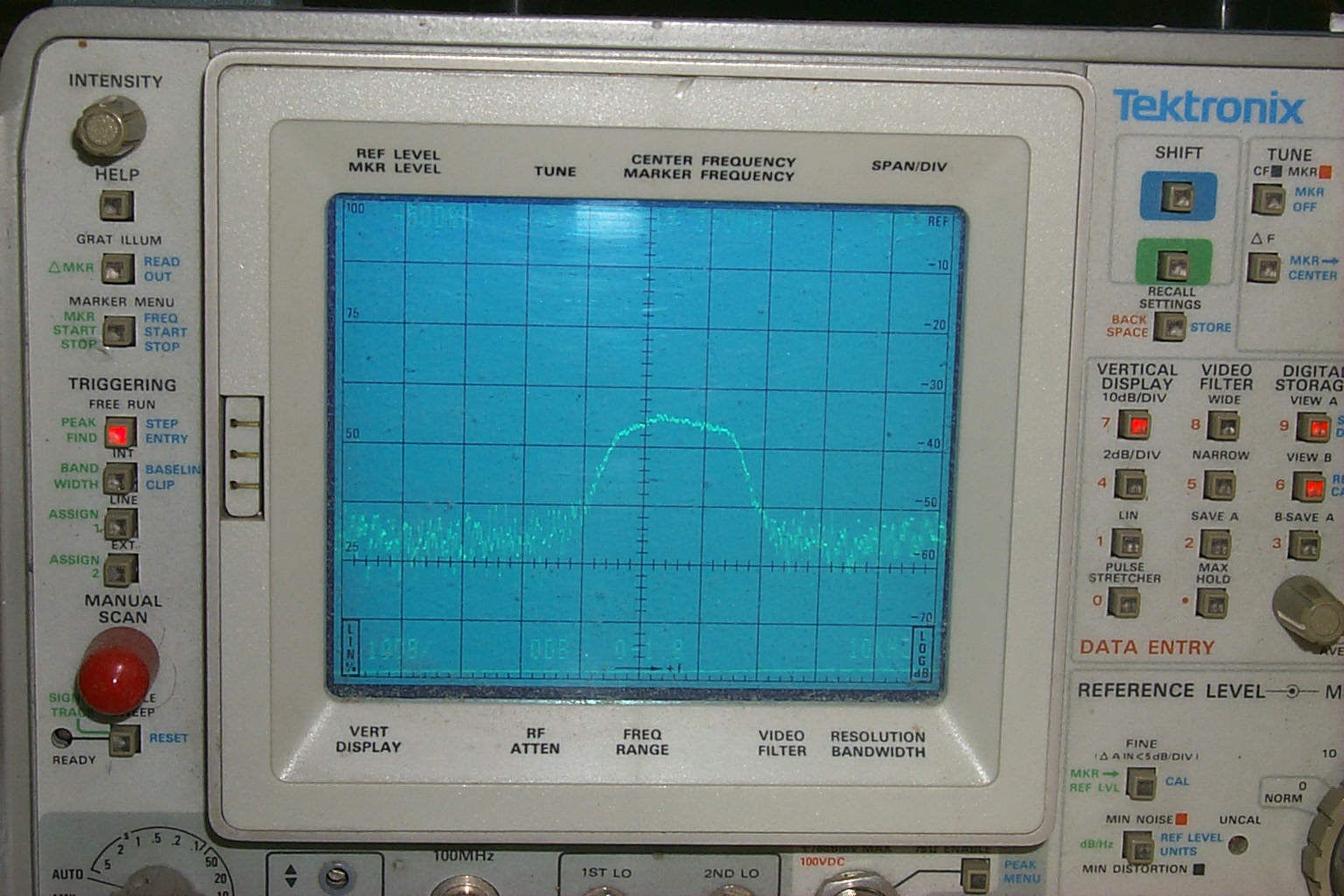
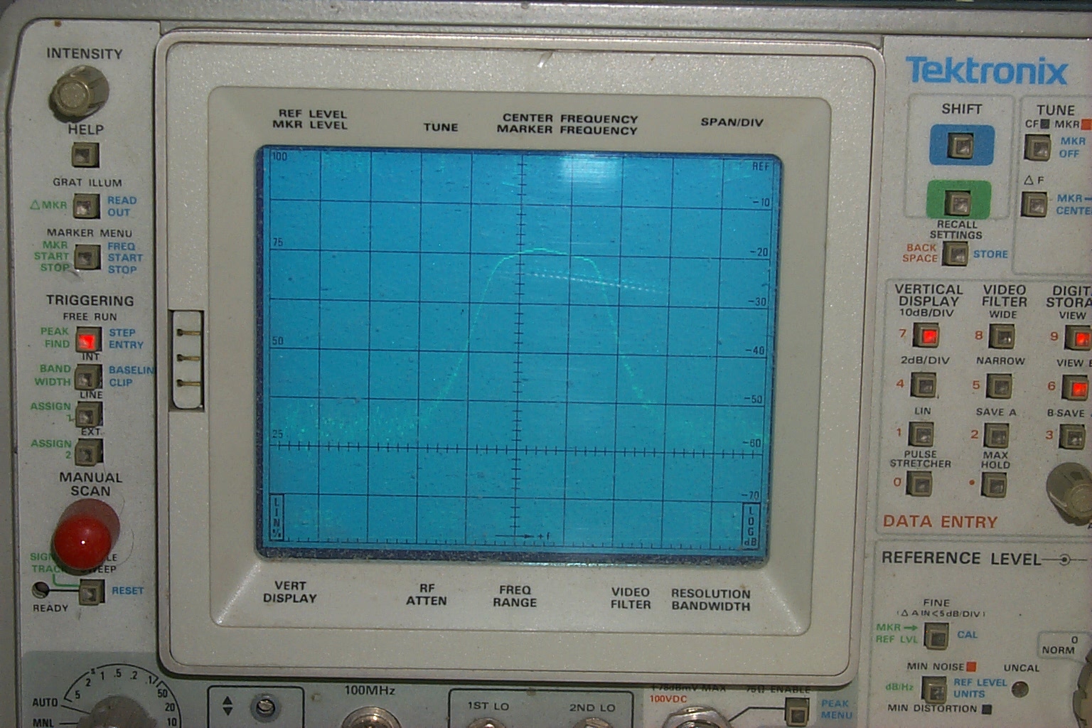
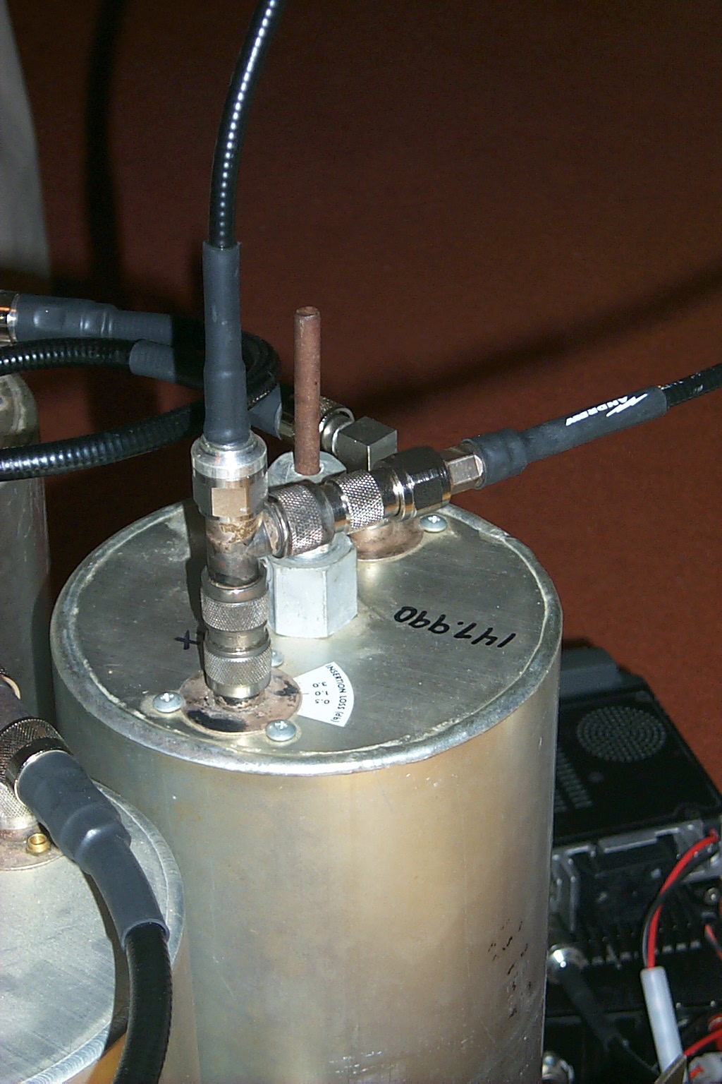
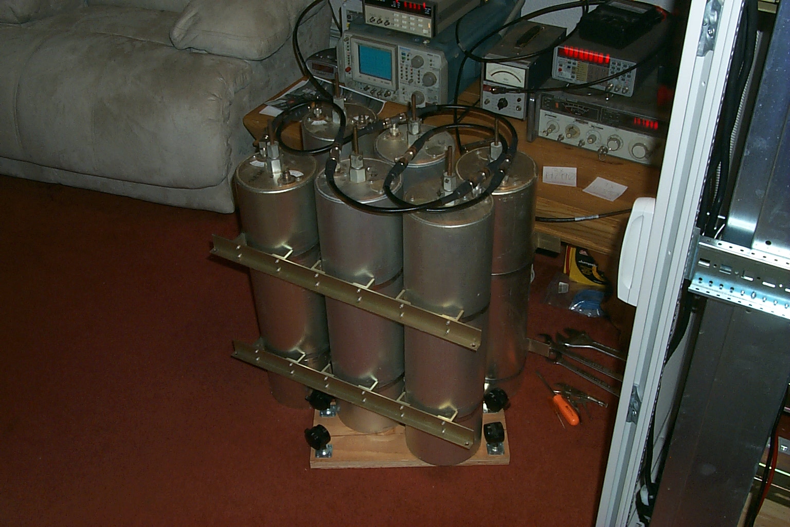
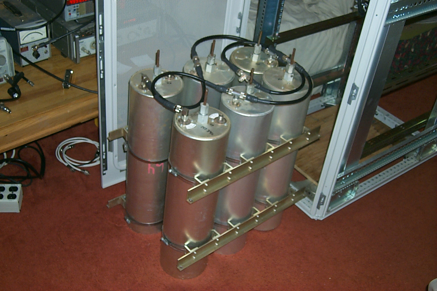
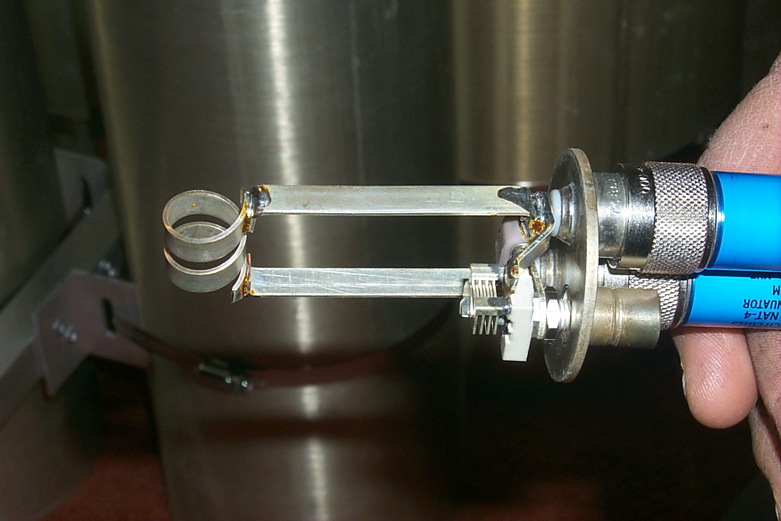
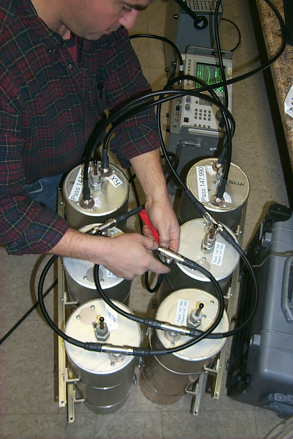
These photos below show the different configurations I used to test for desense using a modified Tee adaptor to inject a weak signal into the duplexer on the receive frequency while transmitting 45 watts into the duplexer on the transmit frequency. My seat of the pants tuning sitting on the living room floor puts the isolation at somewhere about 100 dB plus or minus a few dB for any error in my test equipment setup.

(click on images to enlarge)
Once again John's very patient elmering got me over the top...
WA1ABI - Let me say this:
John's emails always makes me laugh.
Final Assembly
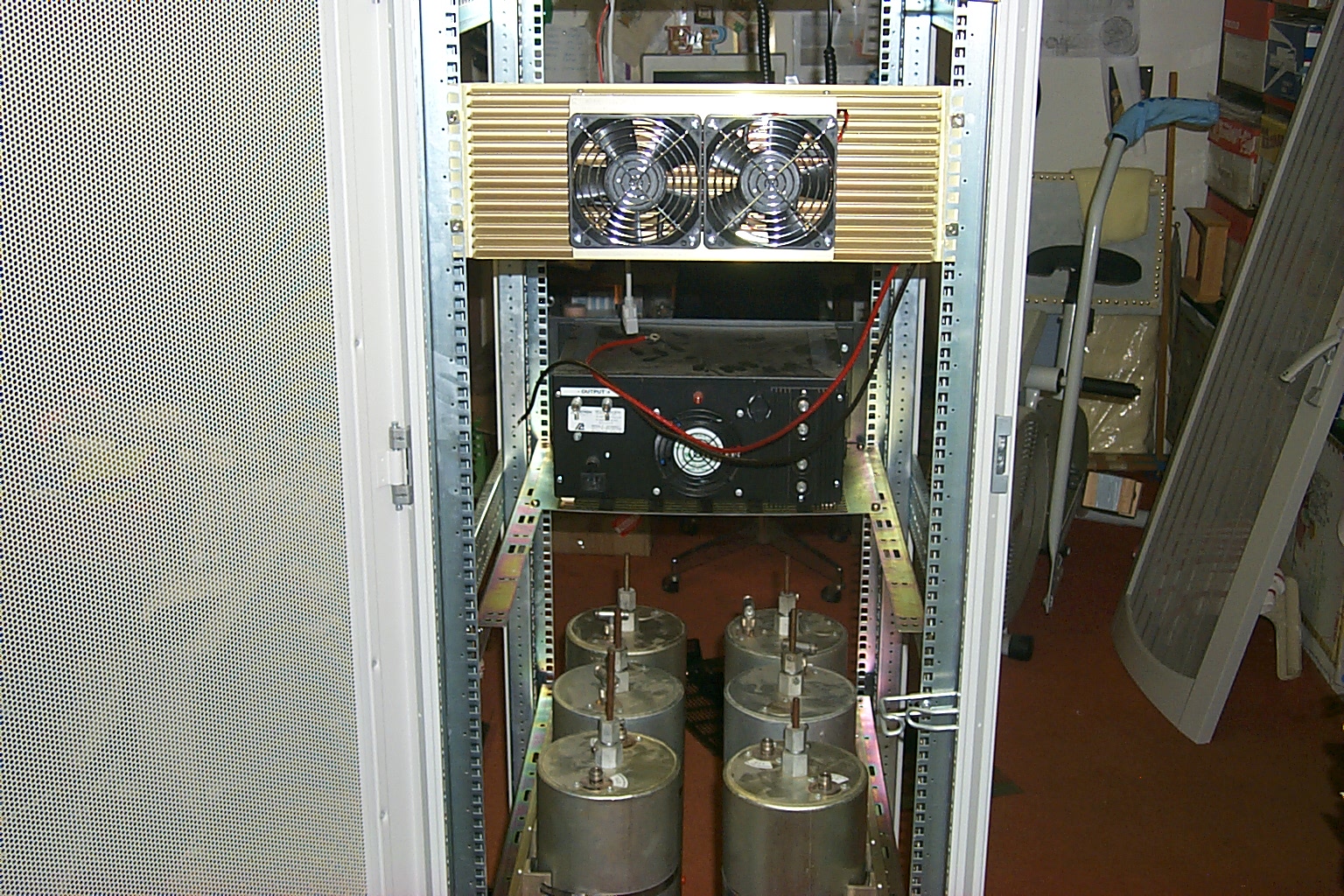
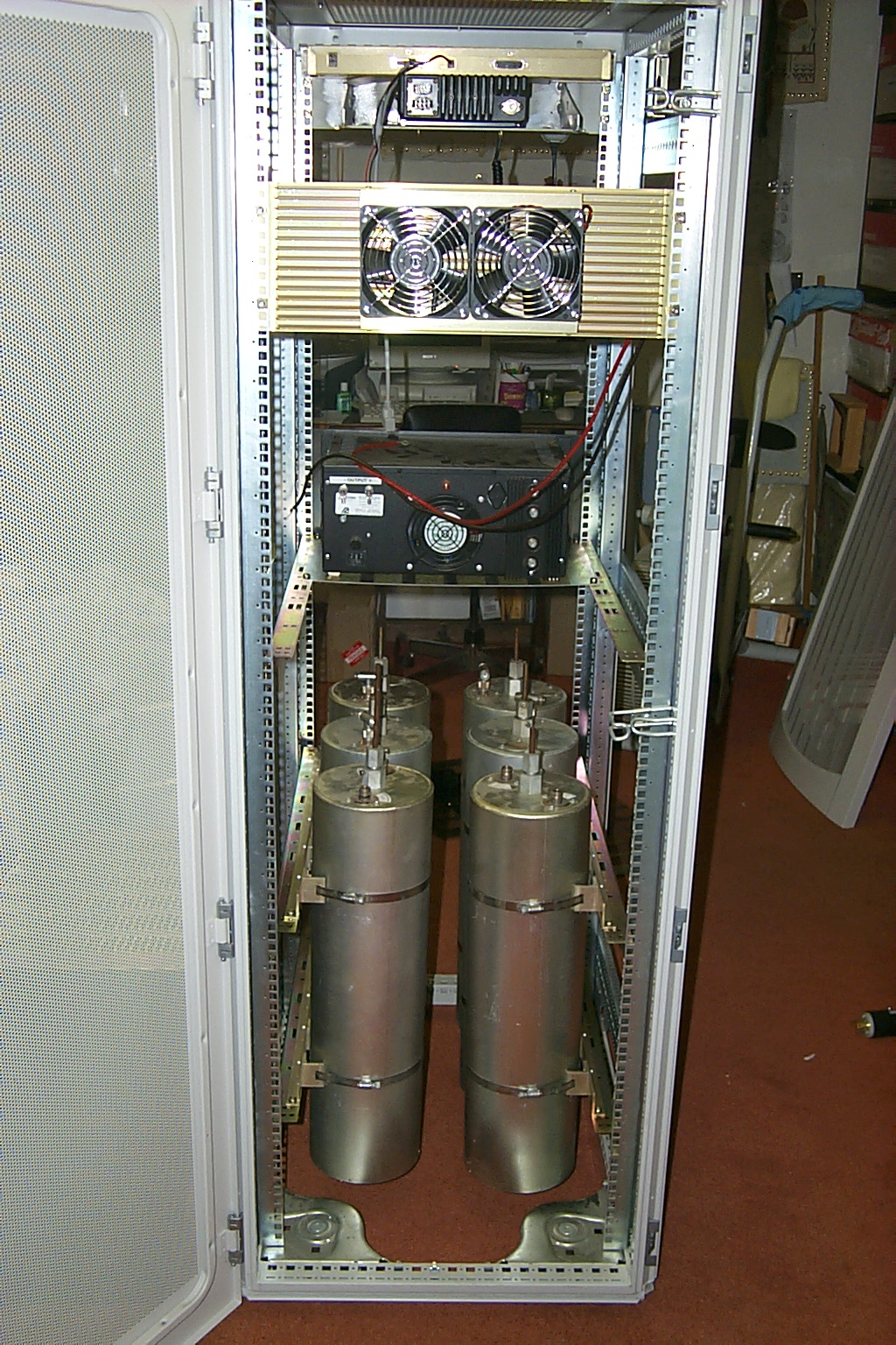
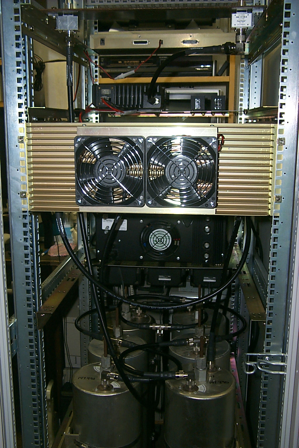
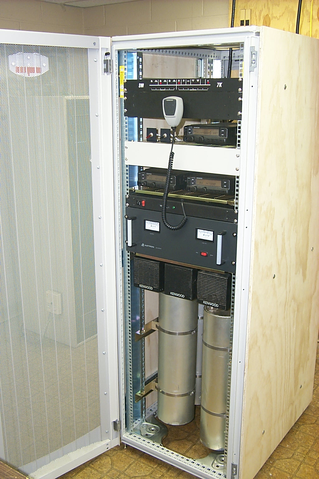
With all of the mounting hardware ready, and the duplexer tuned up, all I had to do was mount everything back into the rack cabinet. I had been running the repeater for over a year with just loose components sitting in the rack, nothing was actually bolted into the cabinet so moving the repeater was quite a chore, that plus the 2 hour 100+ mile round trip every time I had to go down to the Westerly site was growing old.
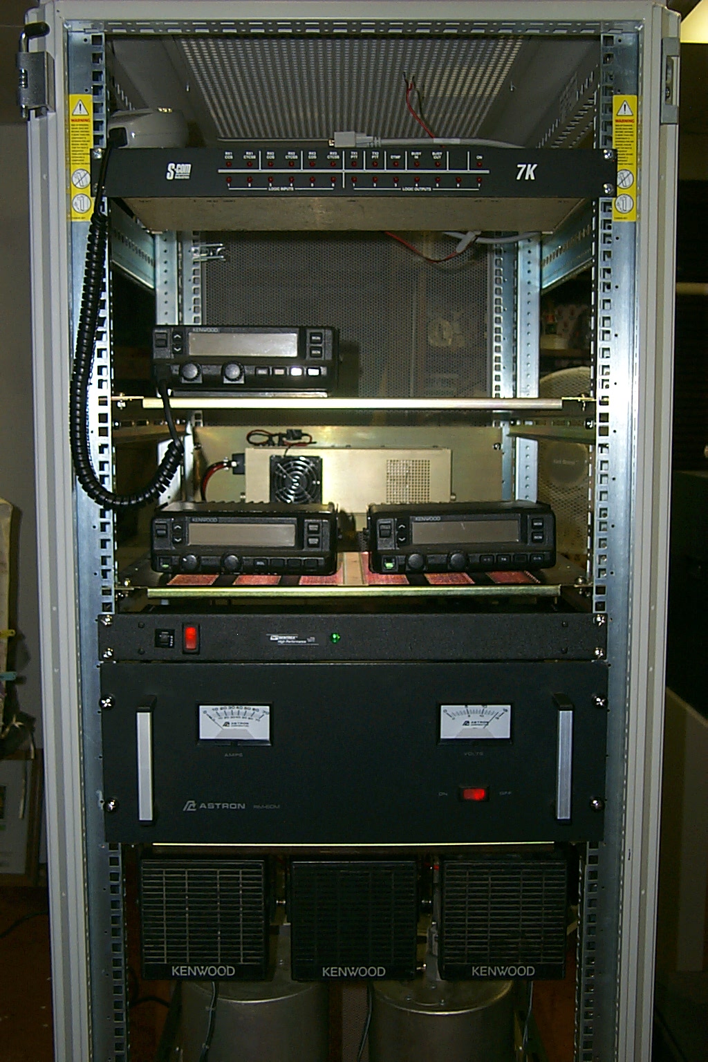
Once again with the help of Sandy's brother we fabricated custom shelves to mount all the hardware into the rack so it could be easily transported. The final assembly went quickly and everything fit perfectly. Again, building on lessons learned from the .075 build, I made sure all the components were accessible and easy to work on.
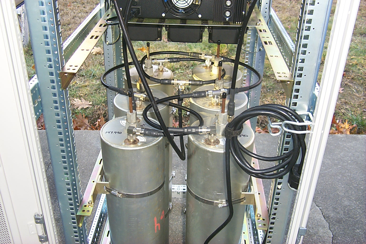
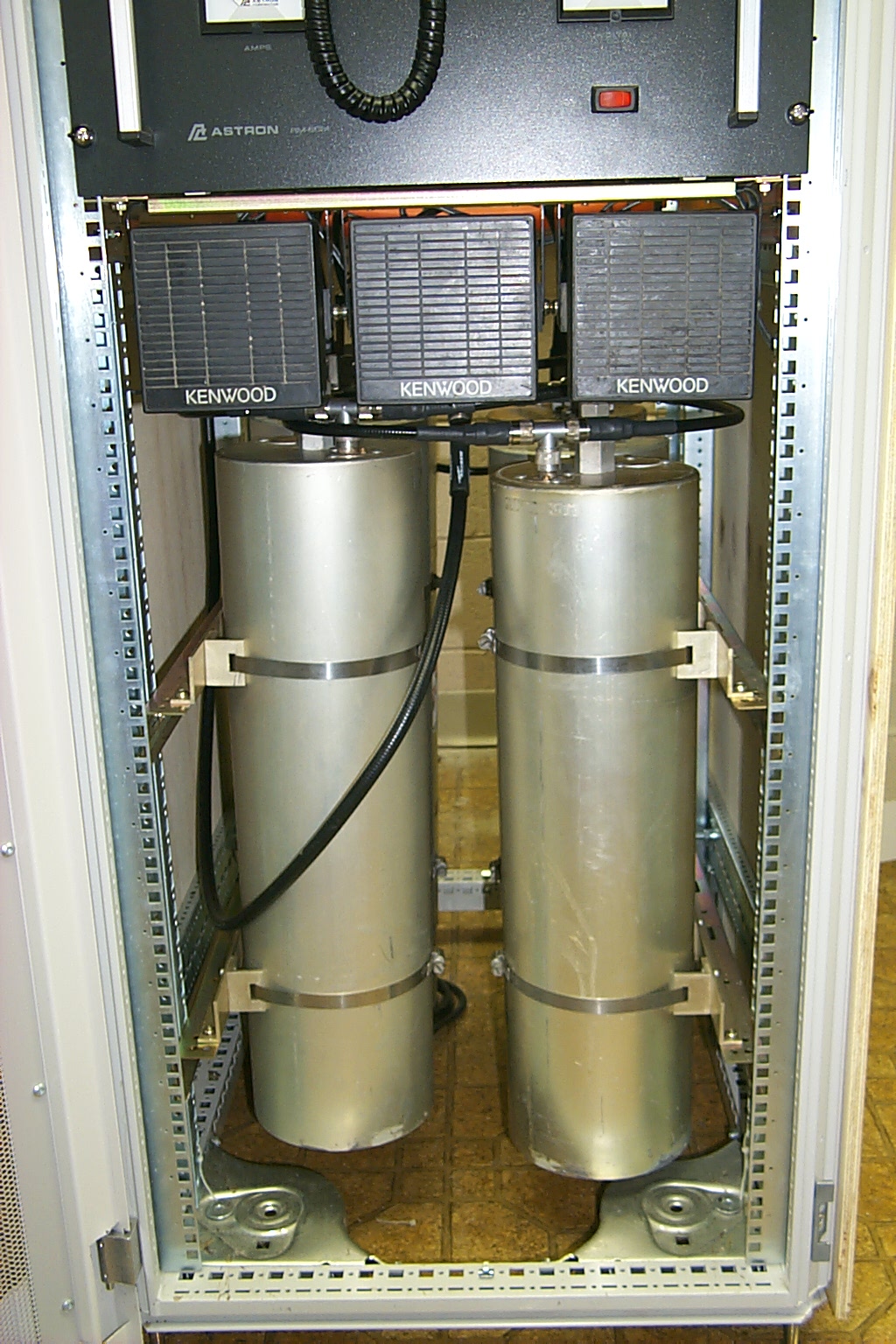
The first step was to mount the tuned duplexer back into the rack
(click on images to enlarge)
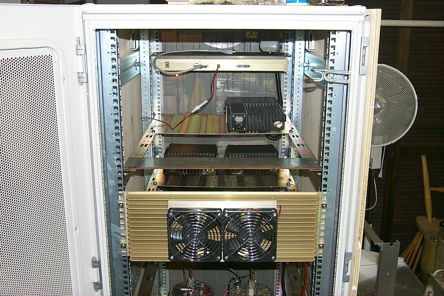
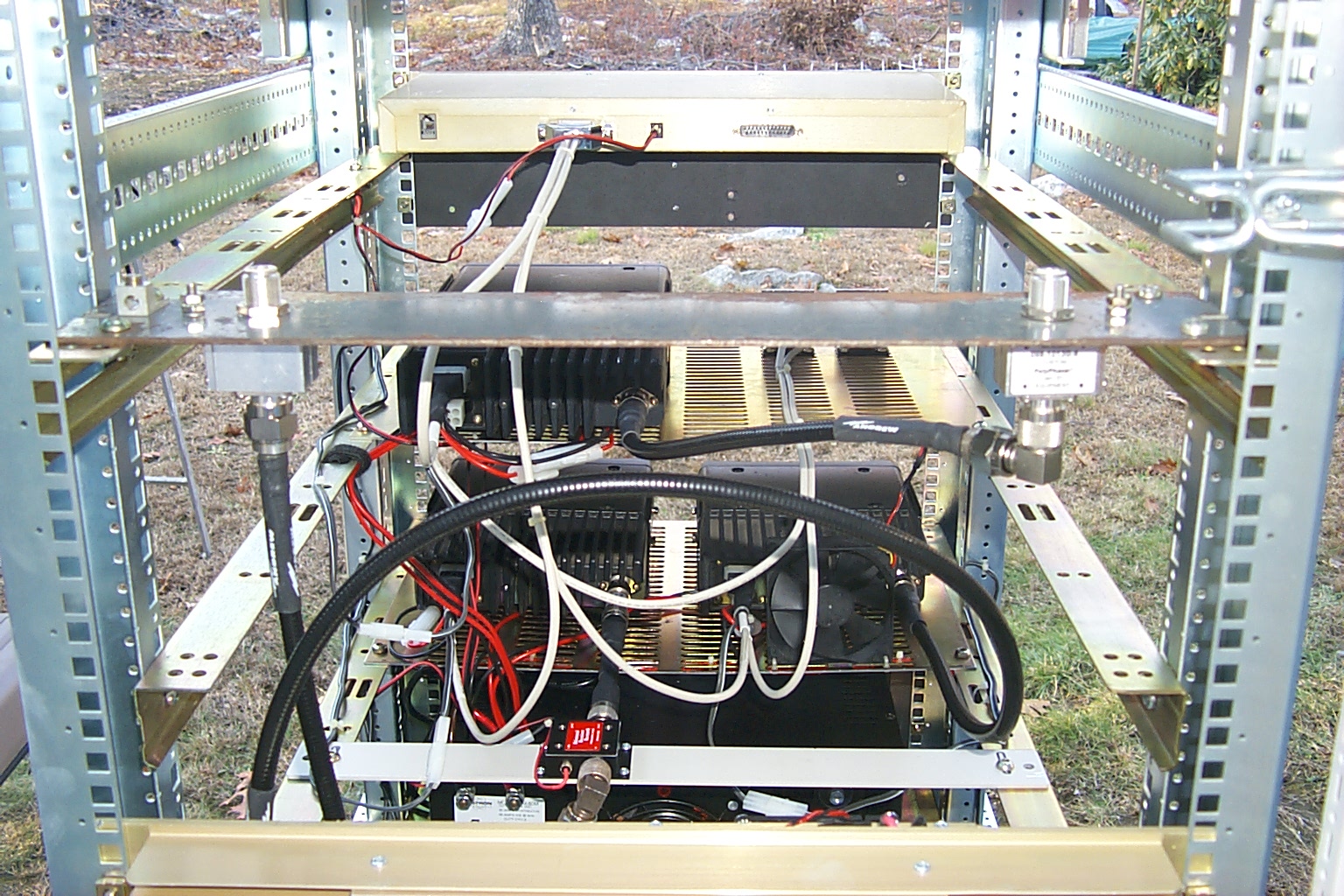
Once I had muscled the tuned cavities back into the rack I mounted all the shelves and started bolting in the radios. The rest of the RF and power cables were very easy to assemble. All I had to do was measure, cut, and install...
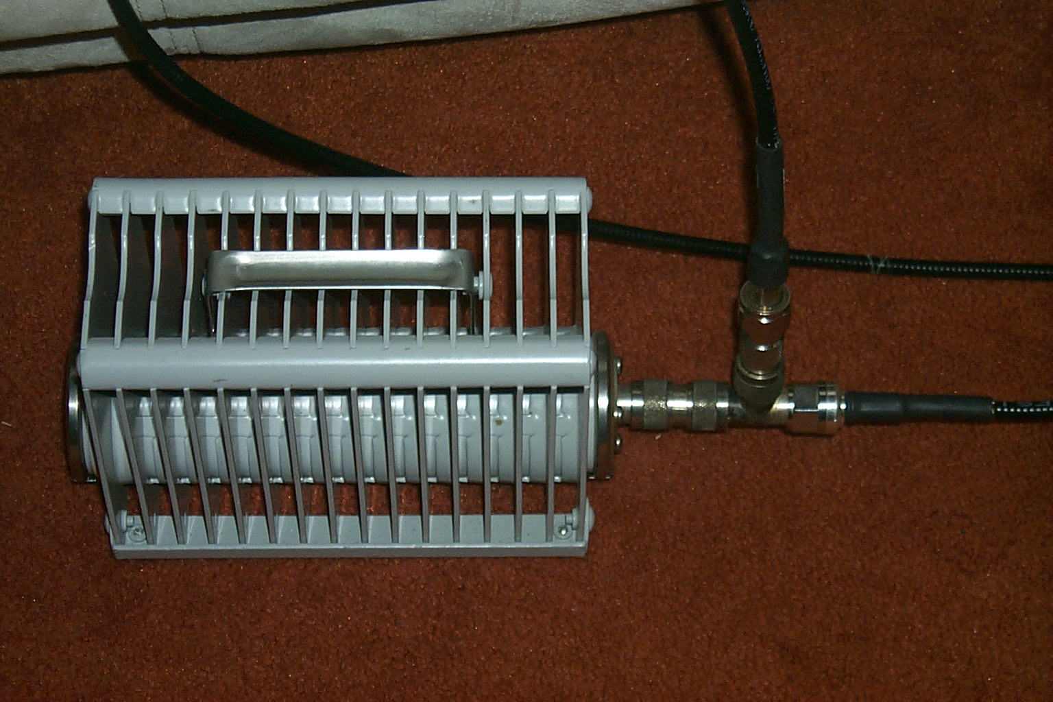
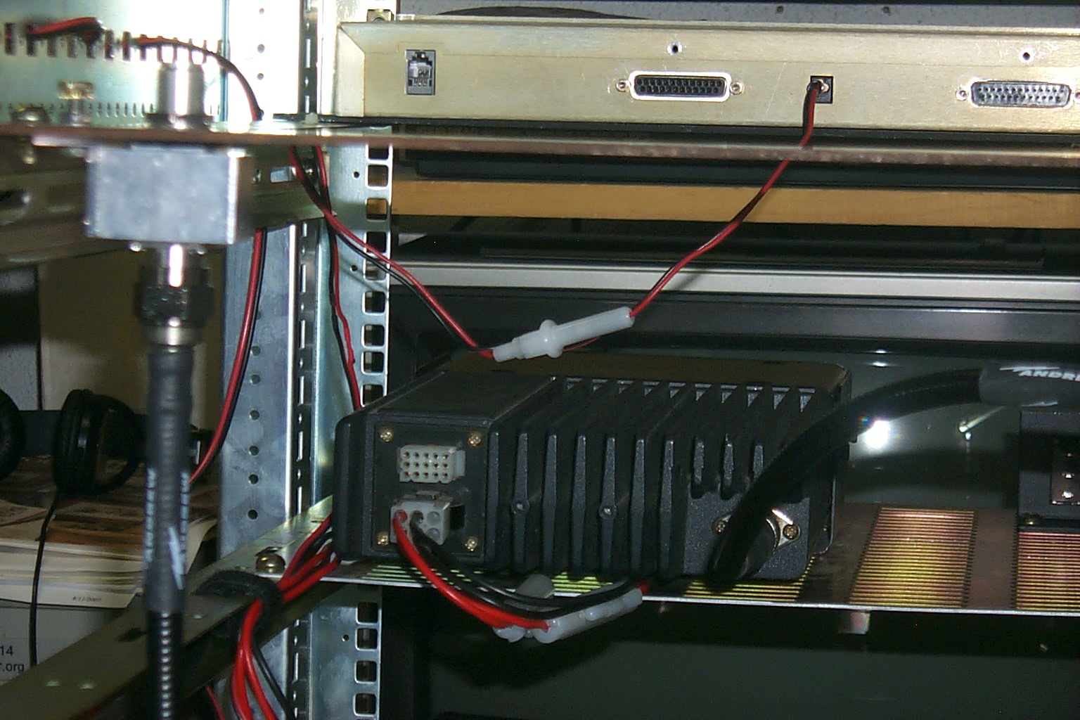
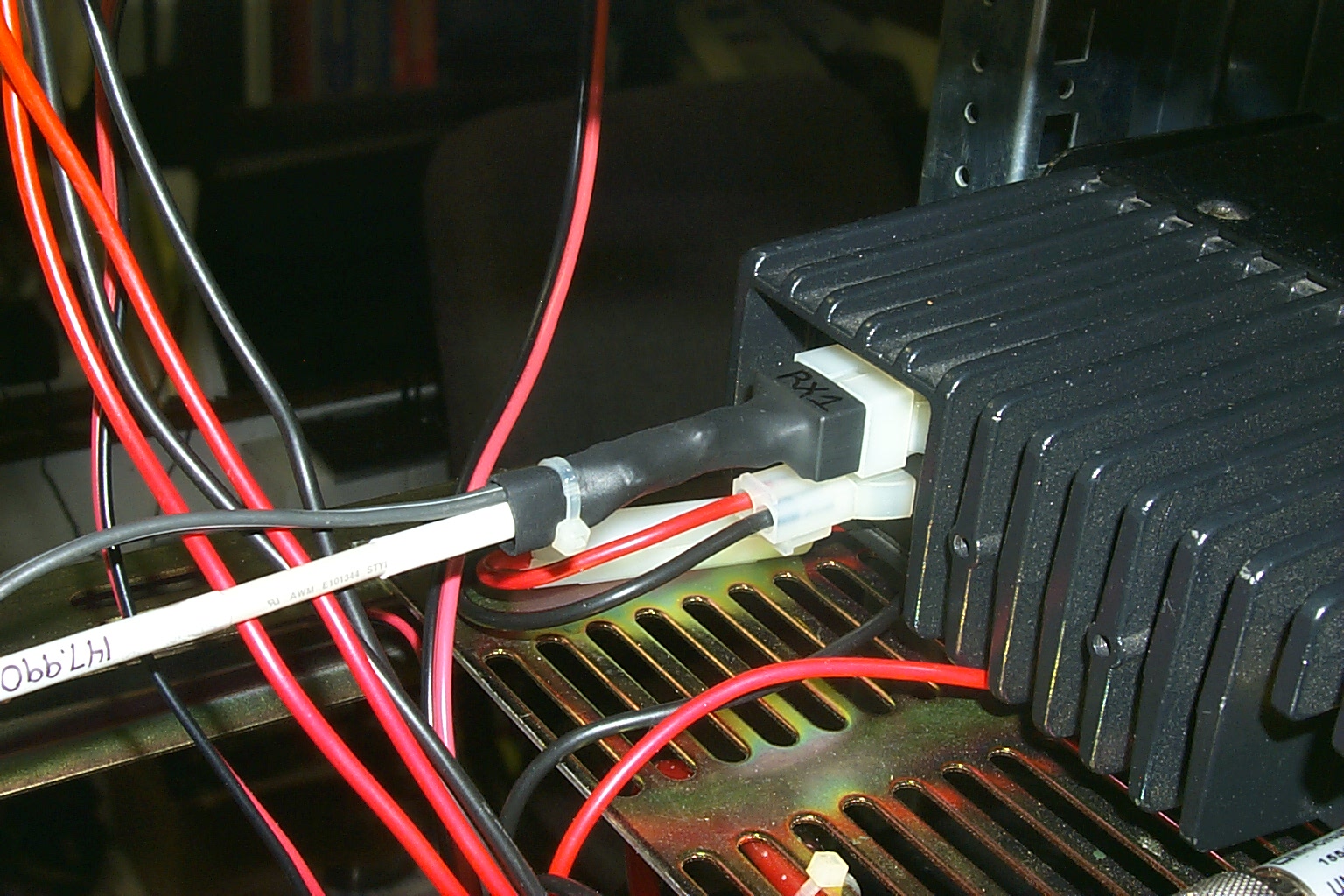
The Receive Pre-Amp
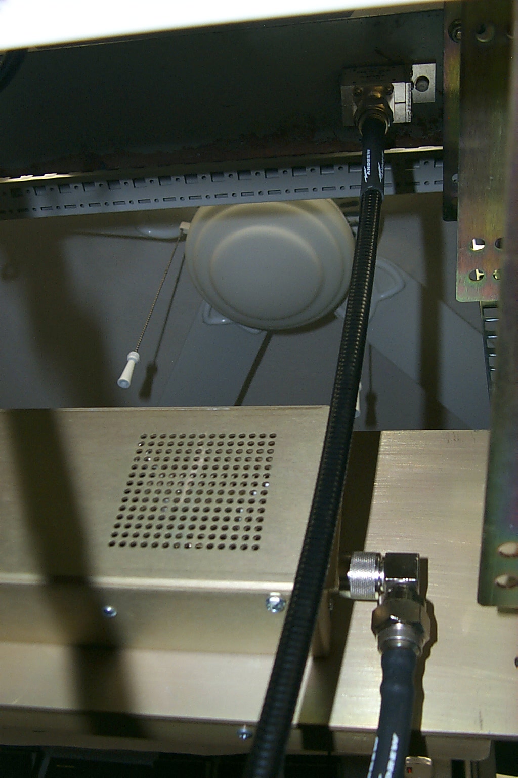
I mounted the receive preamp directly behind the receiver and directly above the duplexer which allowed me to keep both RF jumpers straight and short.
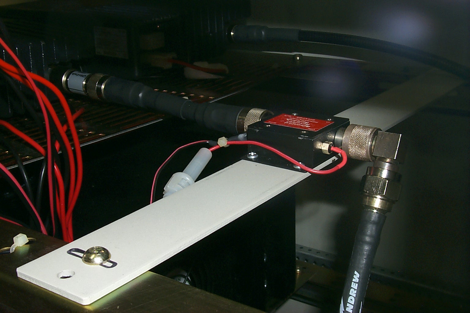
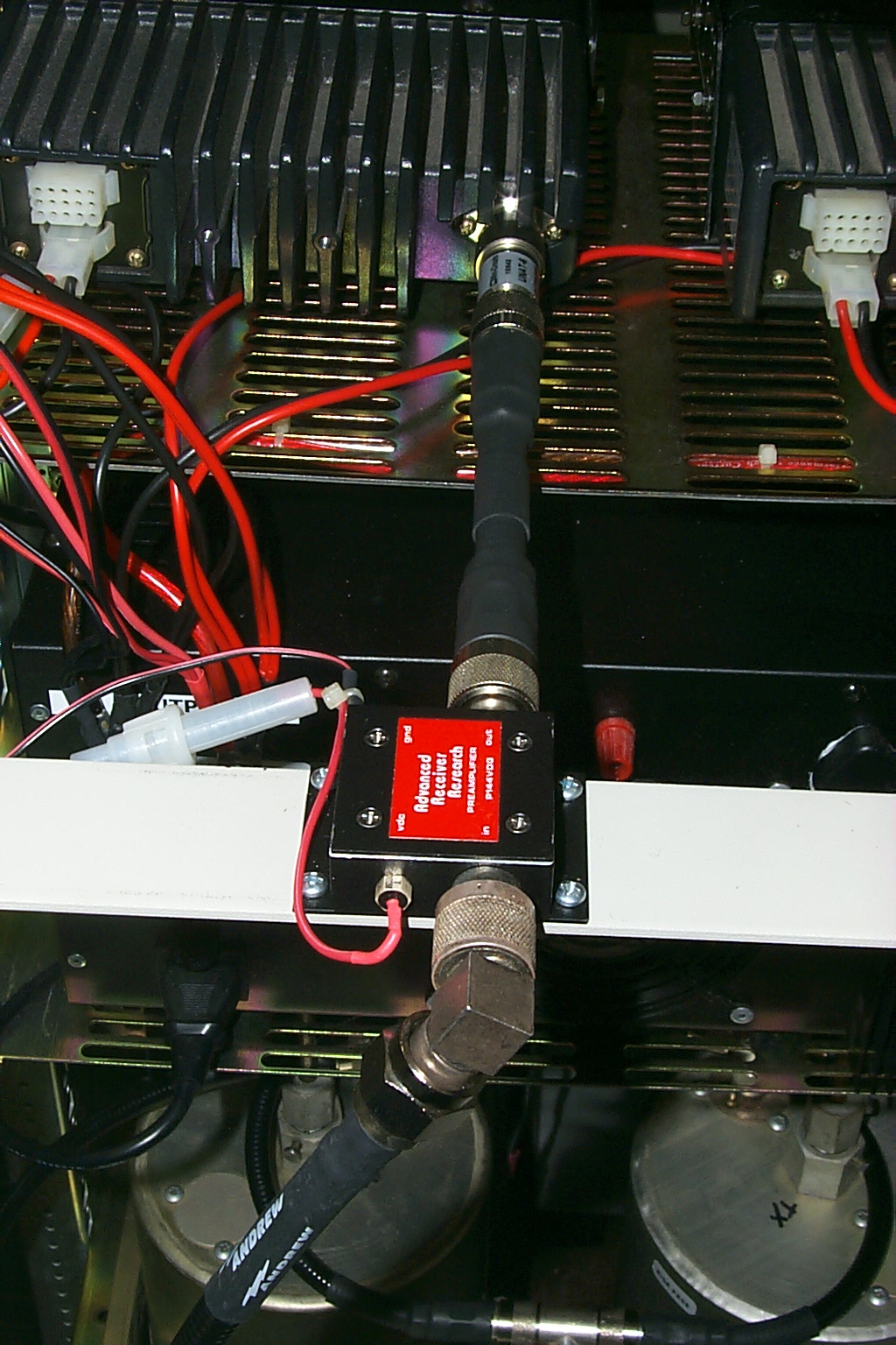
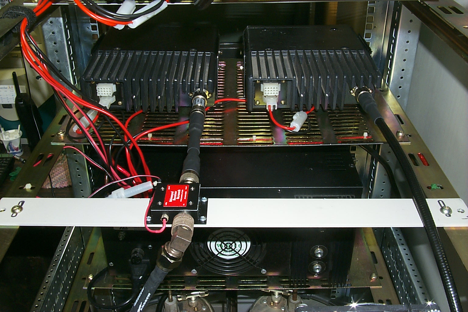
(click on images to enlarge)
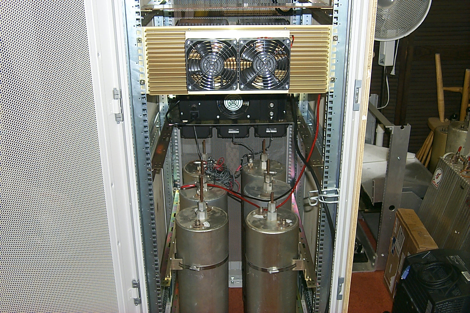
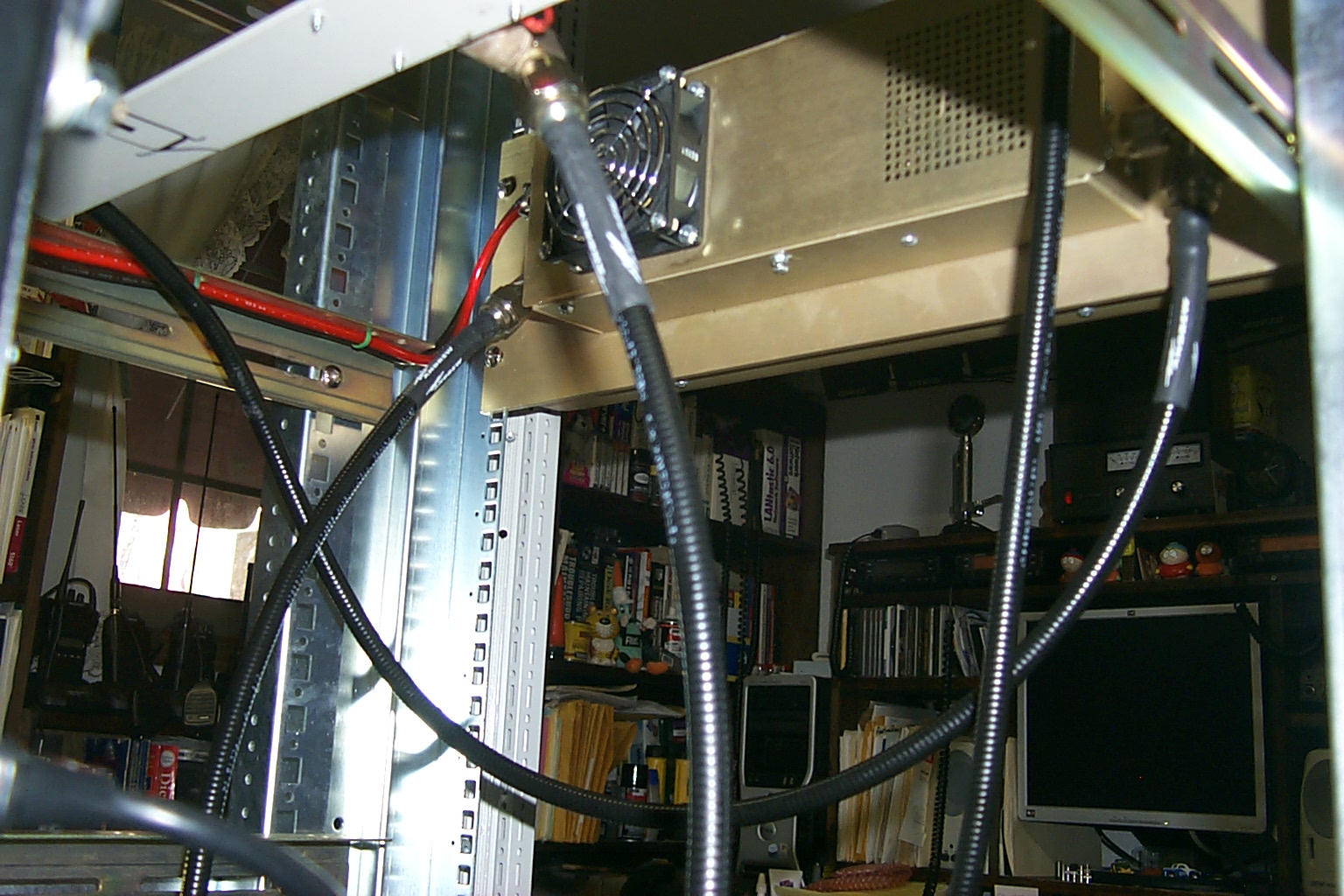
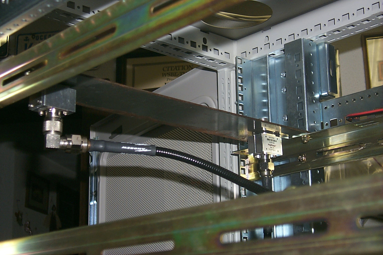
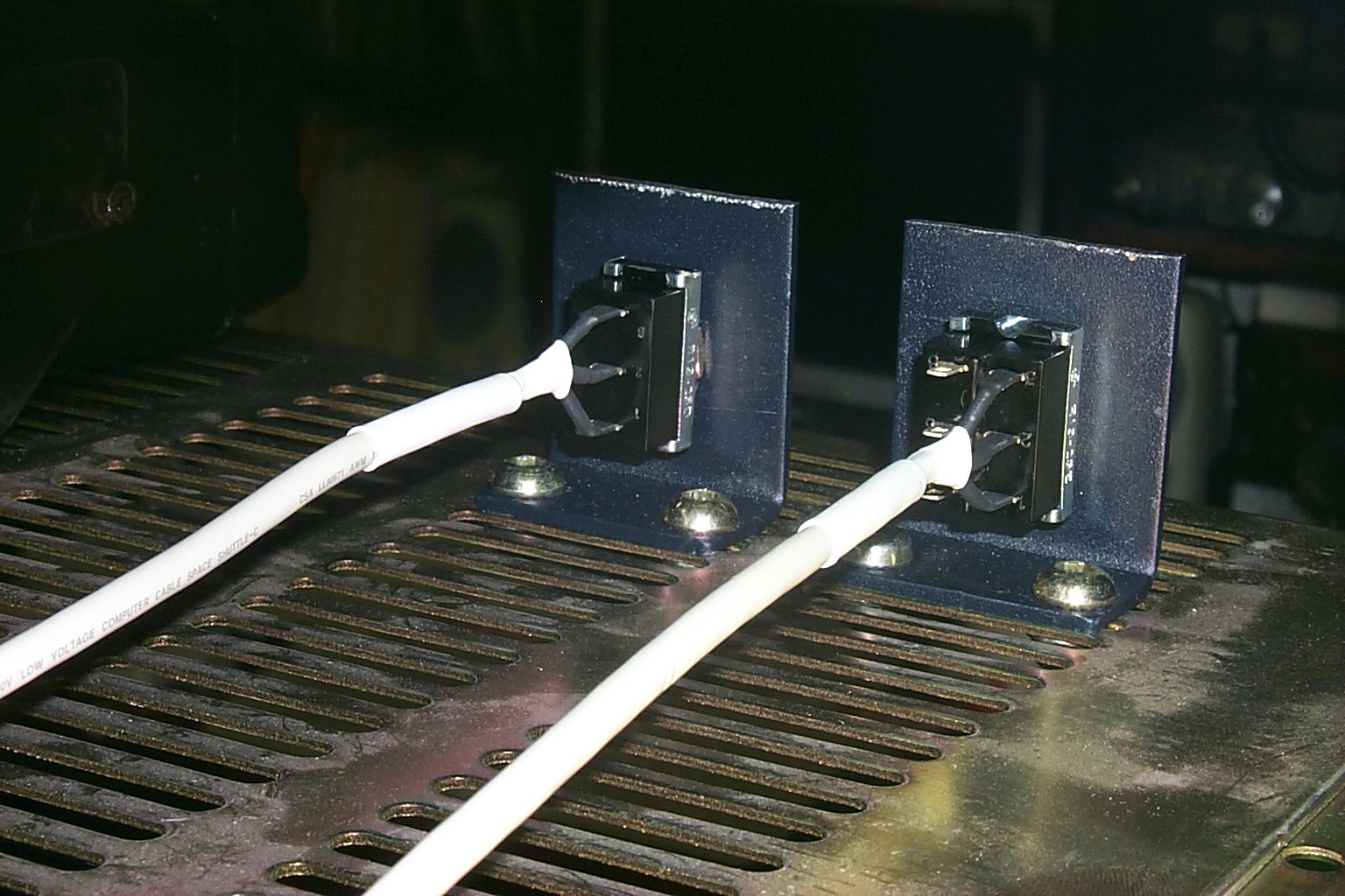
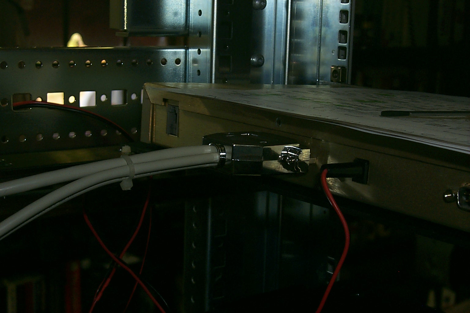
The Polyphasers
Both of the Polyphasers are mounted up top and in the back just inside the rack cabinet. One is for the repeater and the second one is for the UHF link radio.
(click on images to enlarge)
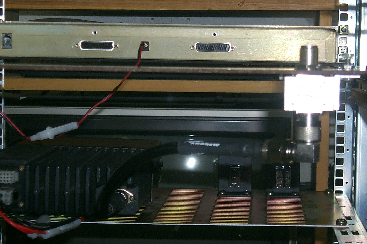
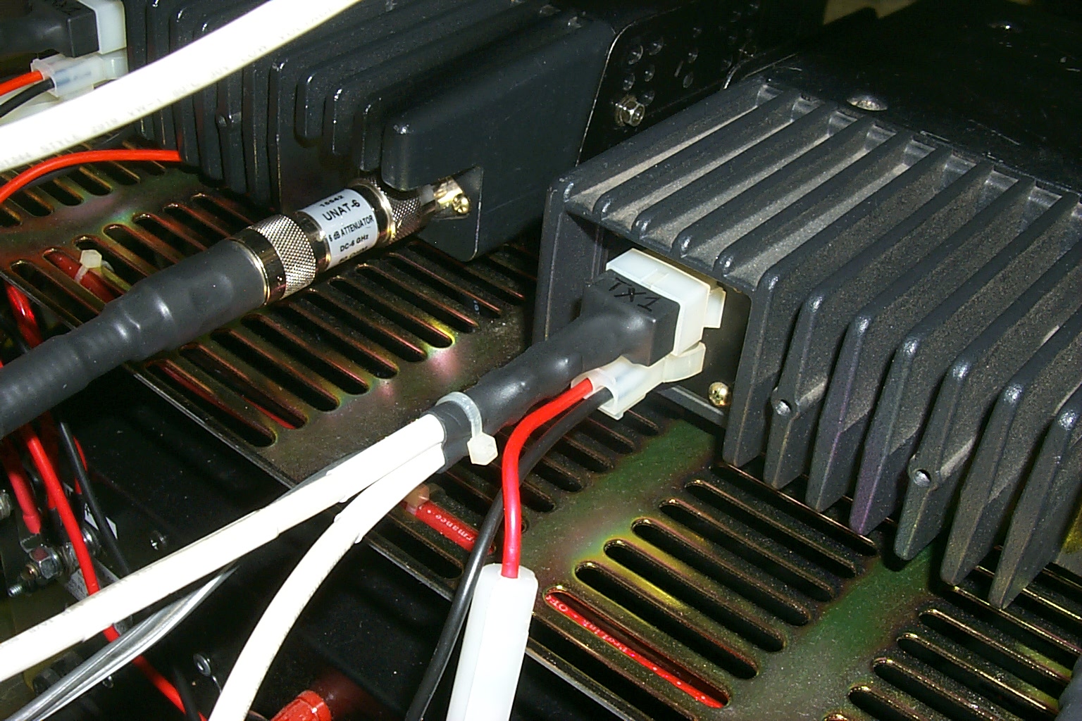
The power amplifier is mounted in the back of the rack directly behind the transmitter and over the duplexer again keeping the RF cables short and straight.
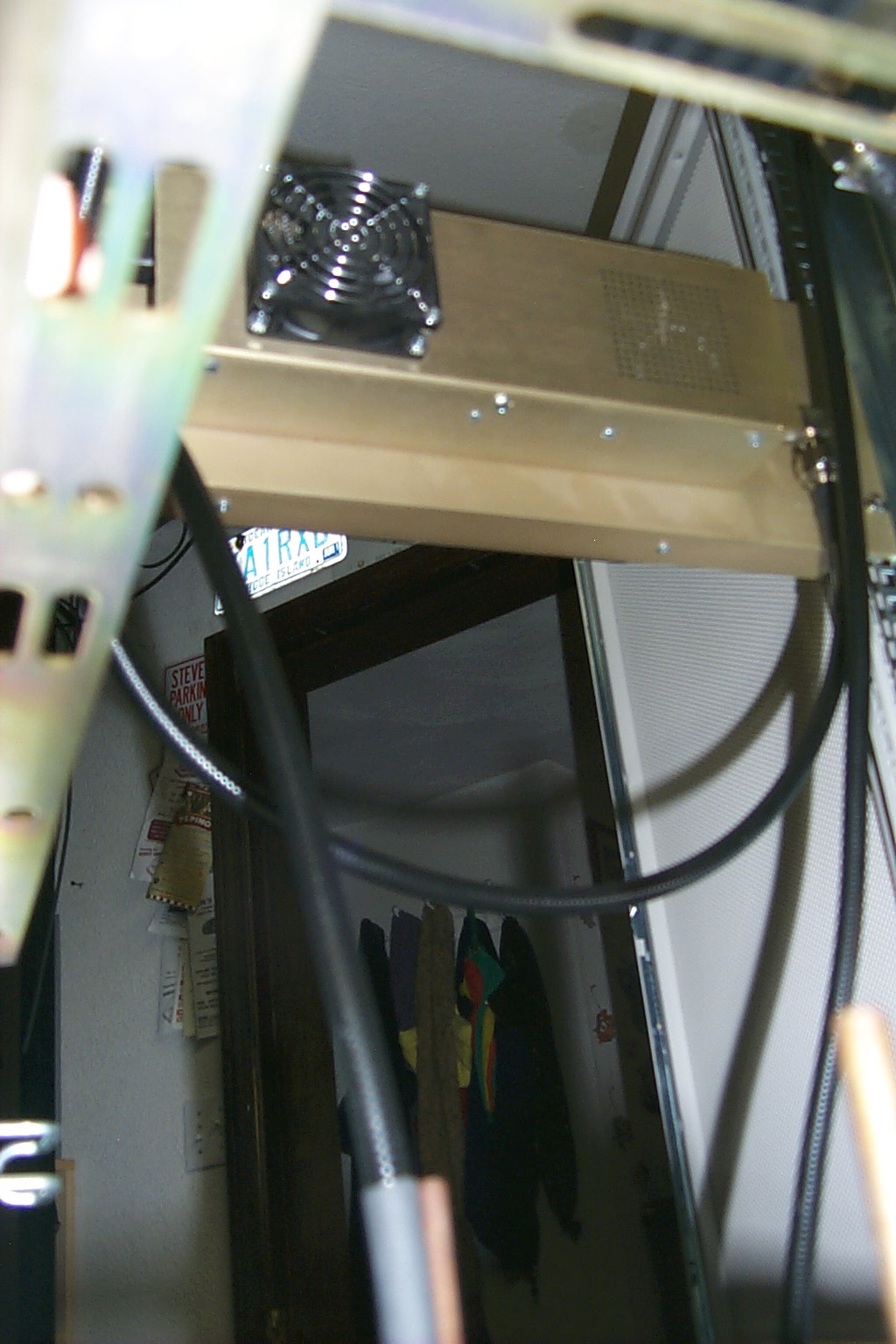
(click on images to enlarge)
Time to make new controller cables...
I had been using a spare set of control cables configured for a S-Com 7K but I wanted to make a new set of controller cables for this rack with TX toggle switches controlling both transmitters. Back to the bench for another marathon "measure, cut, and install session"...
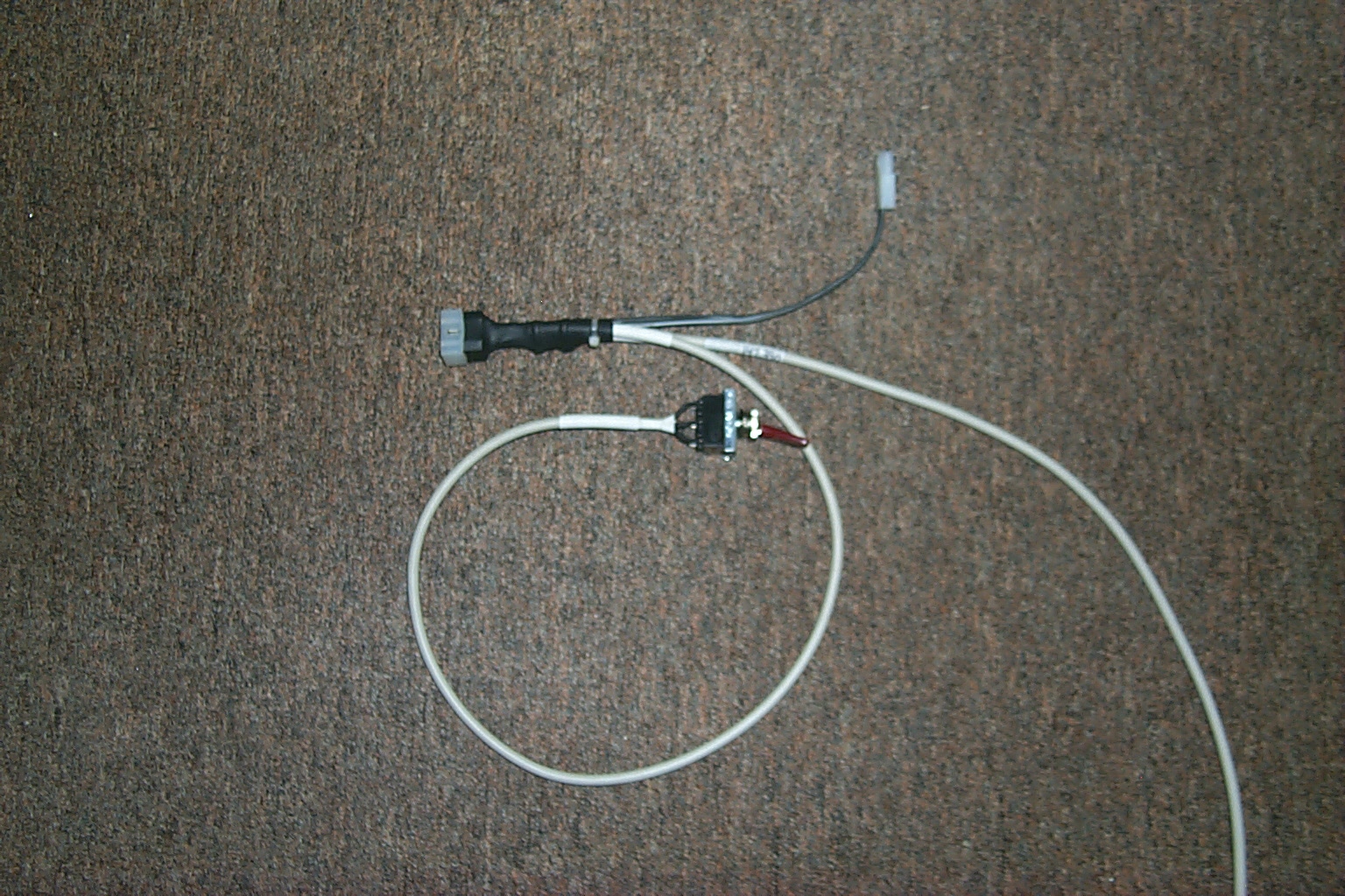
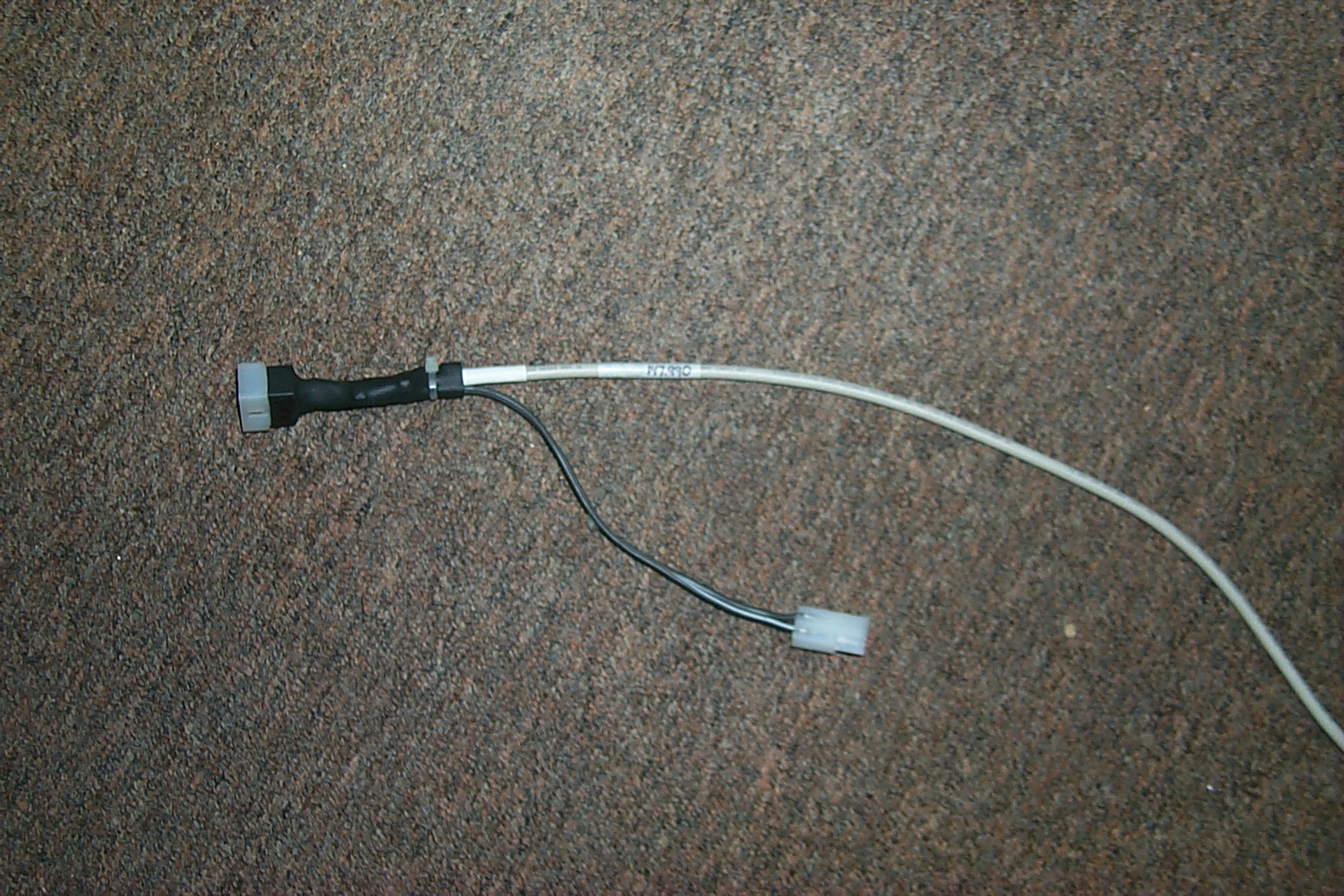
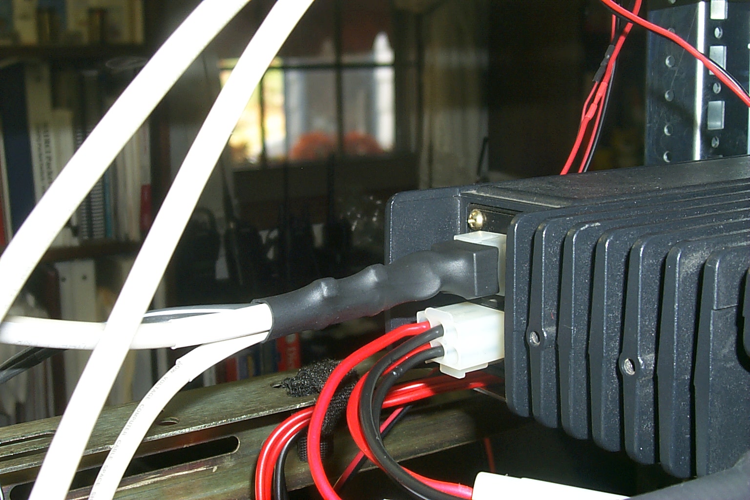
These photos show one of the 15 pin Molex connectors that fit on the back of the TK-30 series radios.
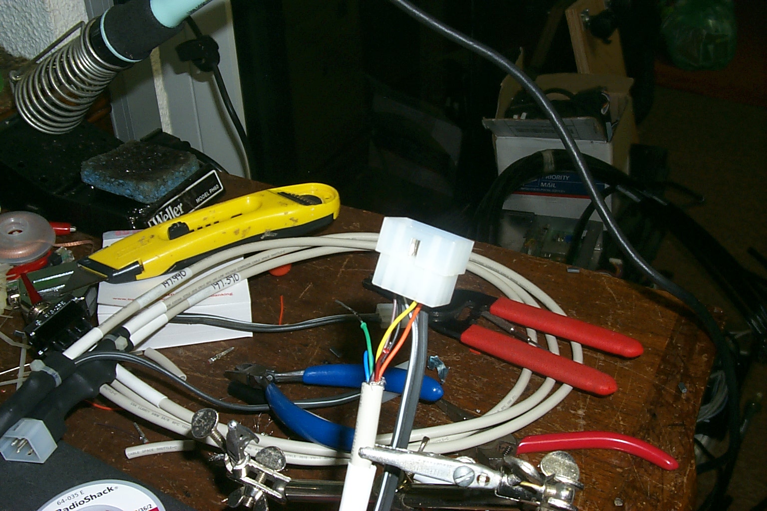

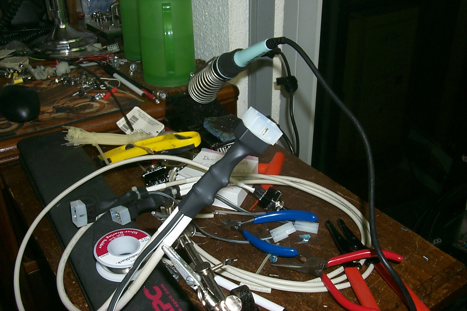
(click on images to enlarge)
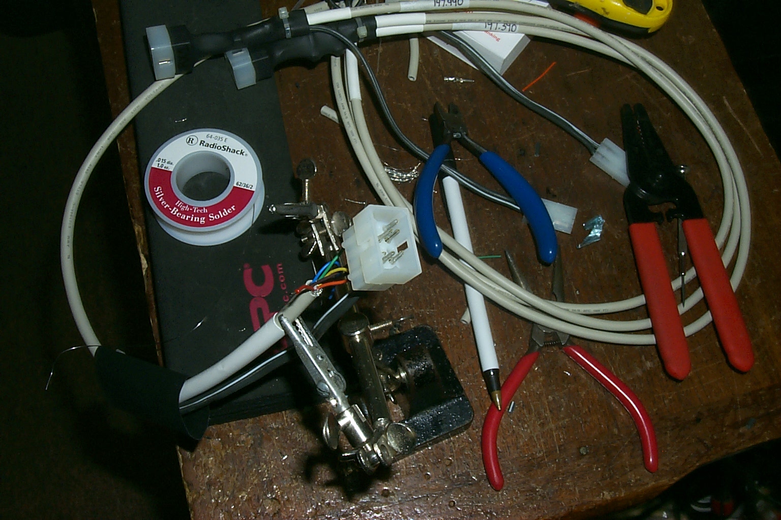
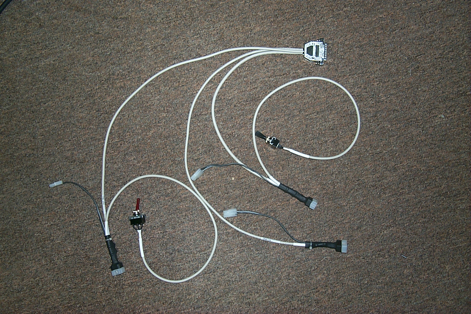
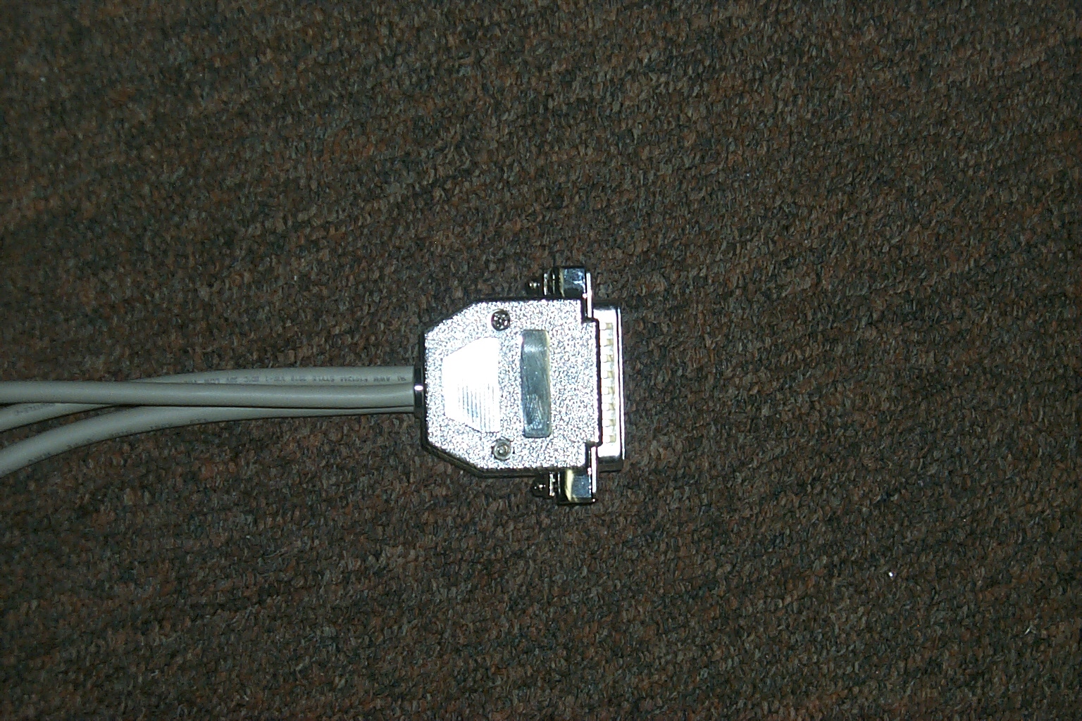
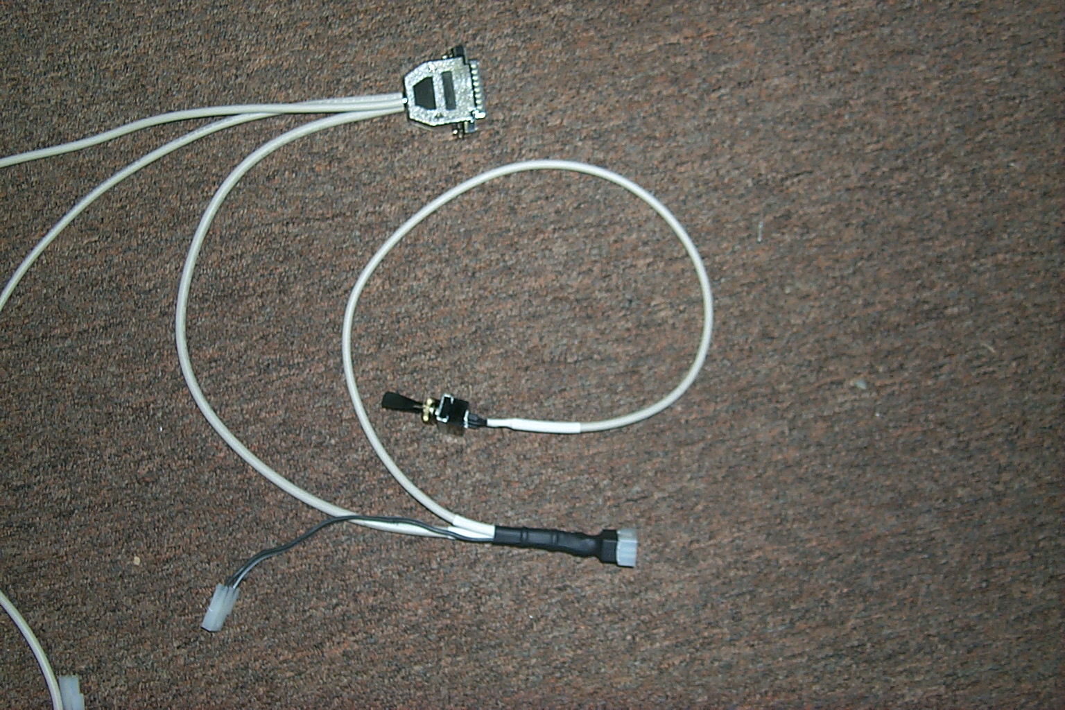
The finished controller cable
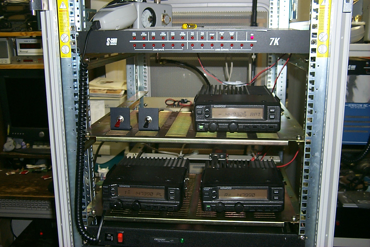
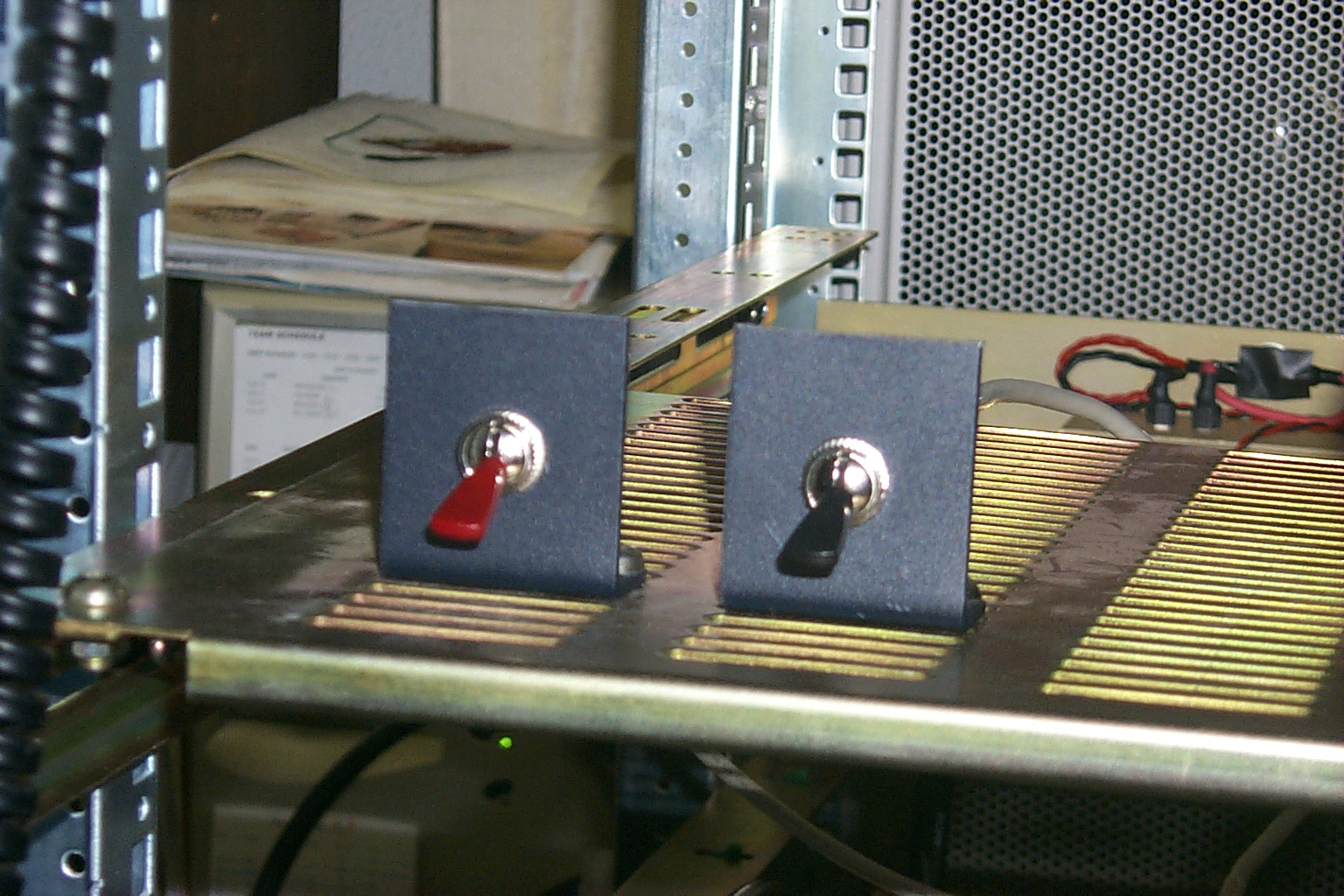
These photos show each of the connections on the controller cable. The DB25 connects to the S-Com 7K controller, the other 15 Pin Molex connectors go to the three TK-30 series radios. You can also see the TX toggle switches and the small Molex connectors for the three local speakers.
(click on images to enlarge)
Time to go back down to Westerly...
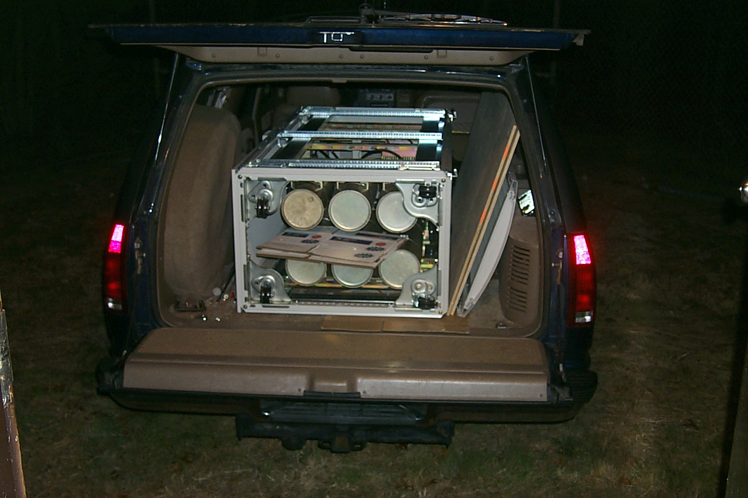
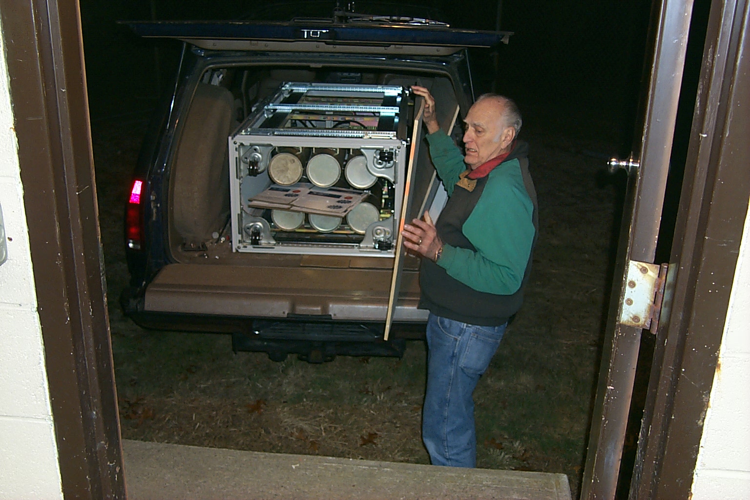
These photos were taken as we loaded all the hardware into the Big Blue Beast
(click on images to enlarge)
After the 60 mile trip south it was dark when we unloaded at the site
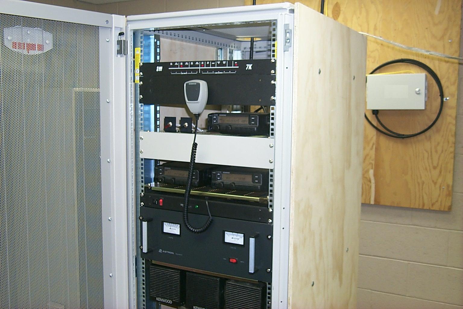
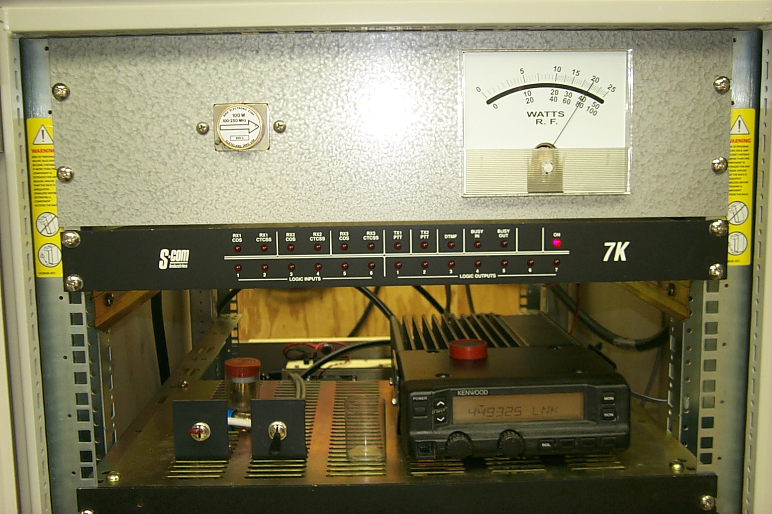
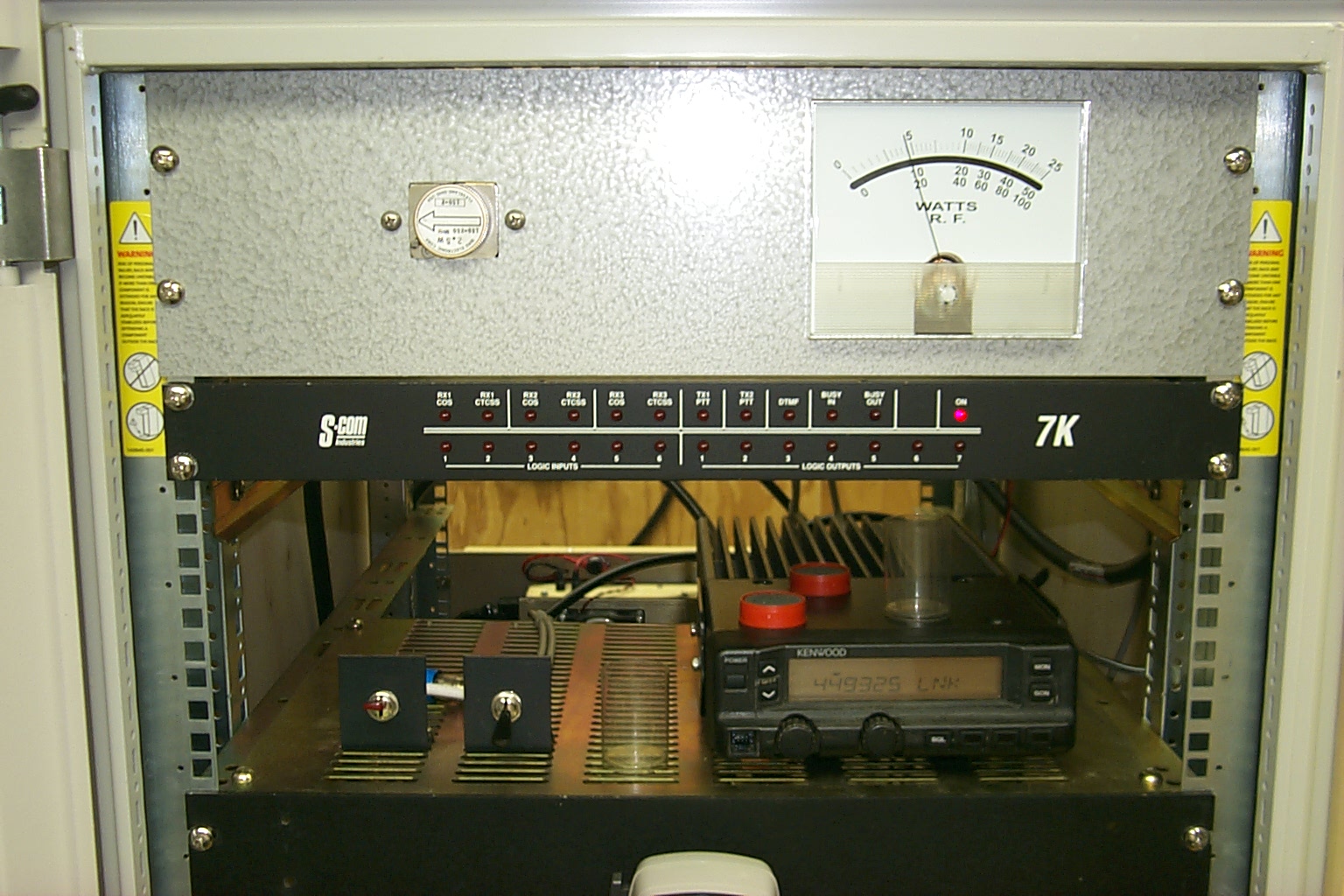
It works!
These last few photos were take just after the 147.390 repeater went back on the air again at the Westerly site. Within the first 5 minutes there were a half dozen amateurs that checked in...
Duplexer reconfiguration Jan 2010
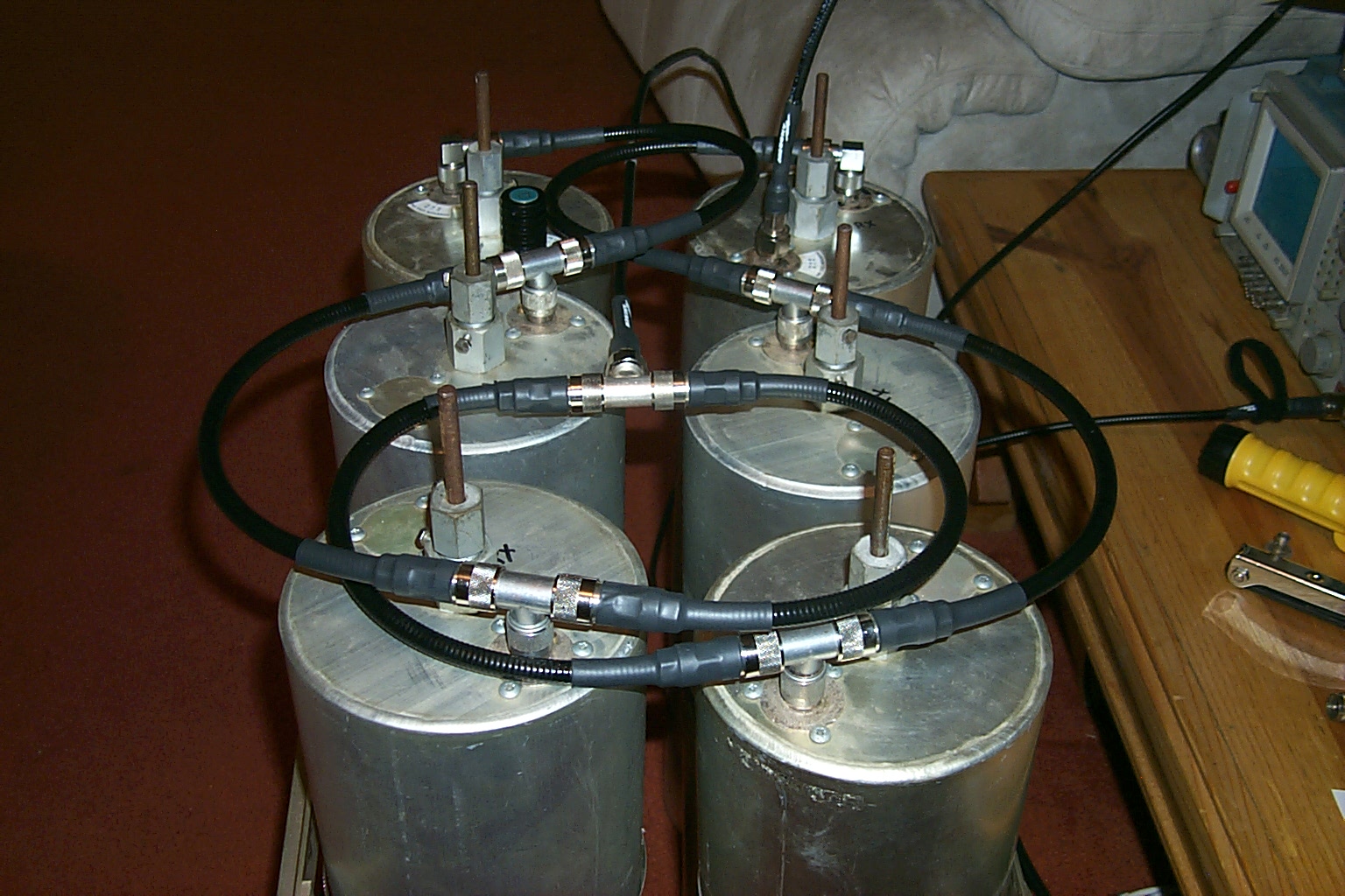
Over the Christmas 2009 / New Year 2010 holiday season Roland N1JOY, Pete AA1PL, and I spent many hours upgrading the 146.760 repeater located in Situate, RI. During these activities Roland & I worked with Brian N1BS during a marathon session tuning the new cavities for the .76 duplexer in the middle of my living room. We spend hours trying different coupling loops and configurations but could not get the performance that we expected.
This are photos of the 146.760 duplexer during our marathon tuning session...
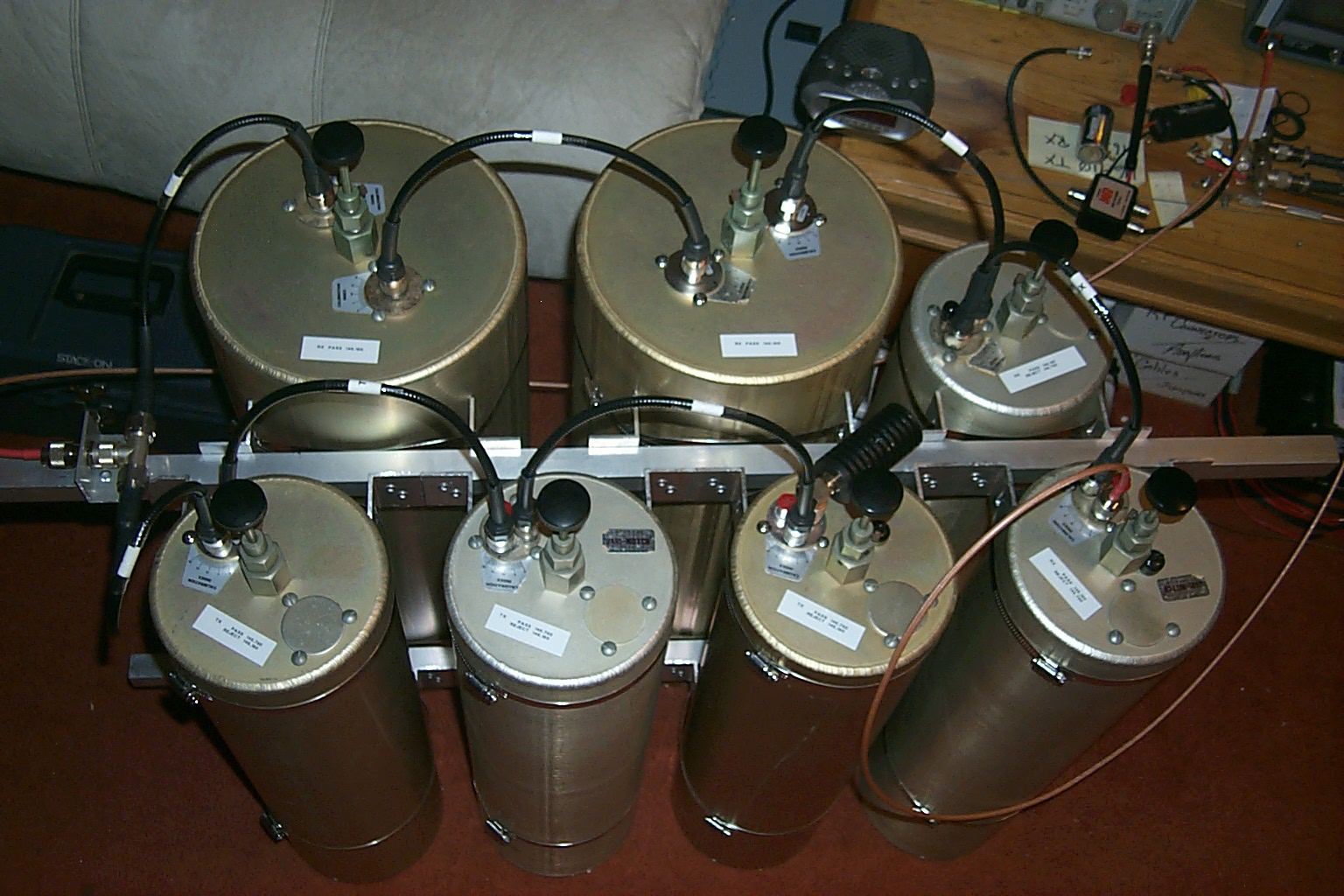
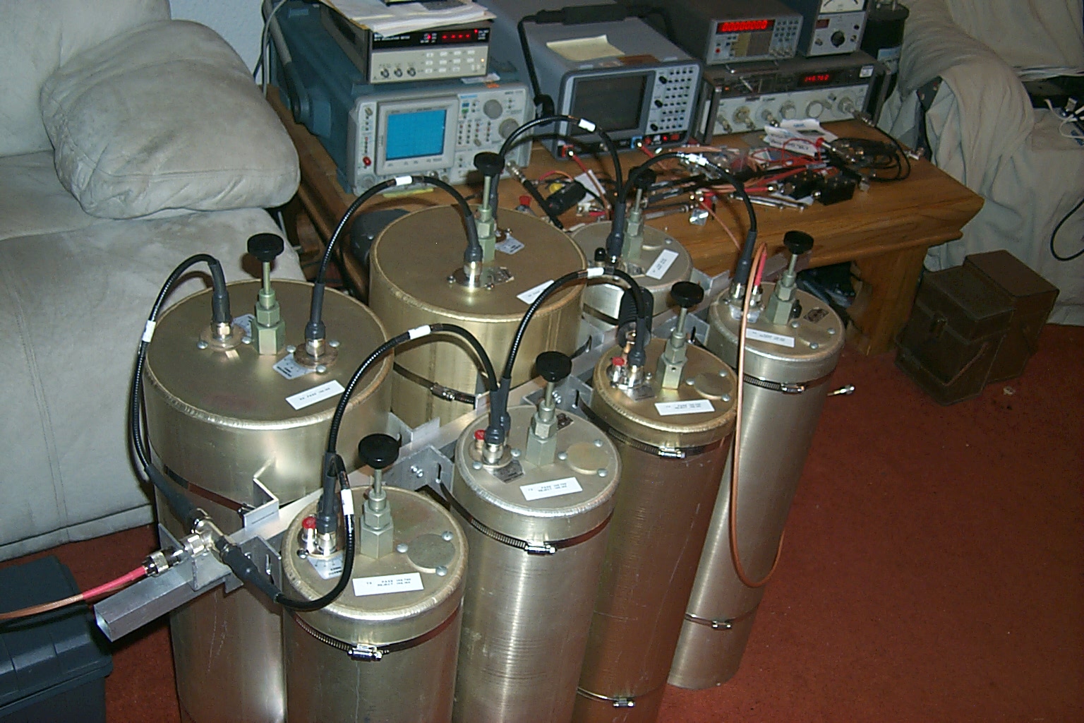
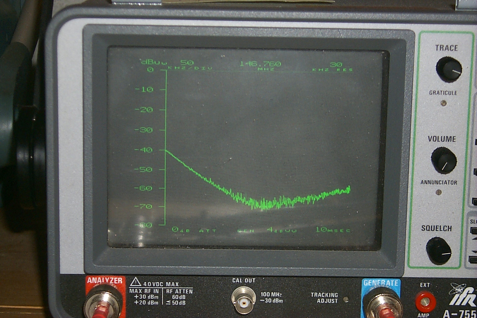
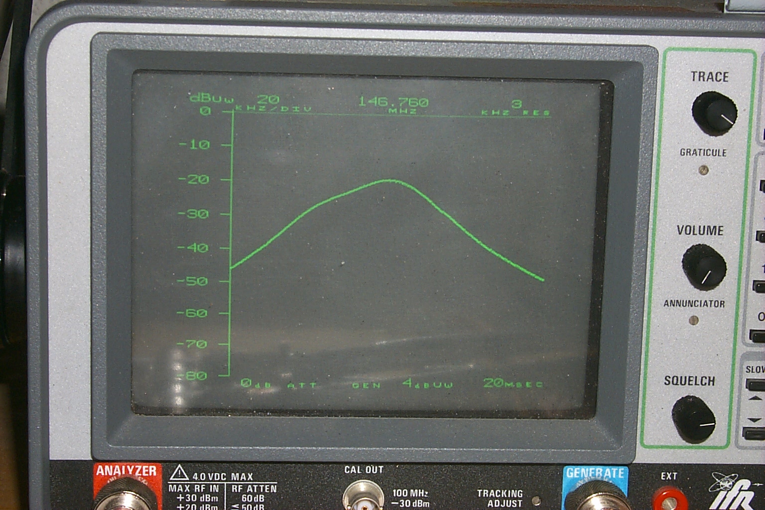
(click on images to enlarge)
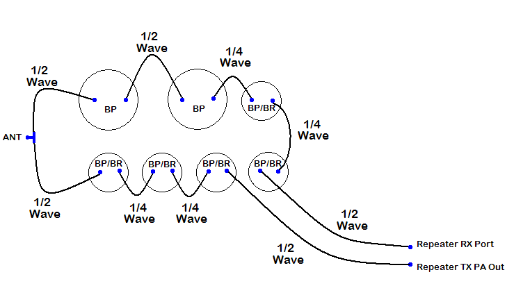
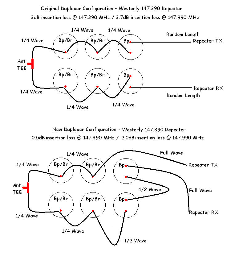
After additional research on the internet and more hours of troubleshooting in the HAMCOW Roland indentified that the jumper cables that make up the phasing harness between the different cavities needed to be either 1/4 wave or 1/2 wave depending on which cavities they were connected to. The Bp/Br cavities needed 1/4 wave cables and the Bp cavities needed 1/2 wave cables. Once this issue had been identified Roland was able to make some new jumpers and the tuning / performance of the cavities improved dramatically.
(click on images to enlarge)
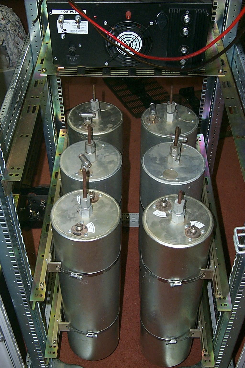
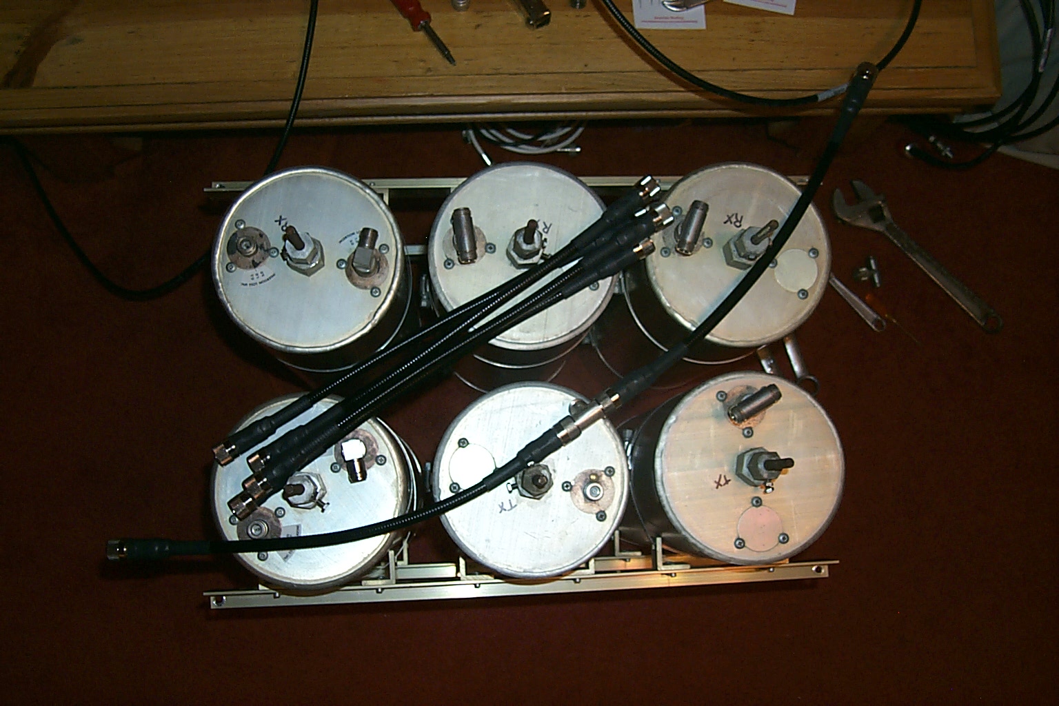
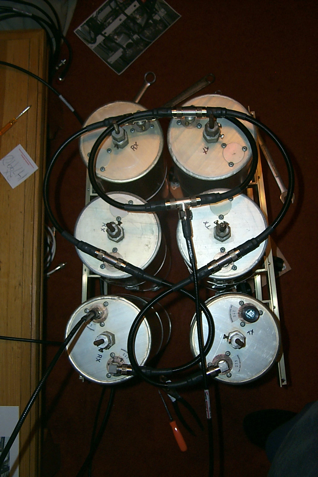
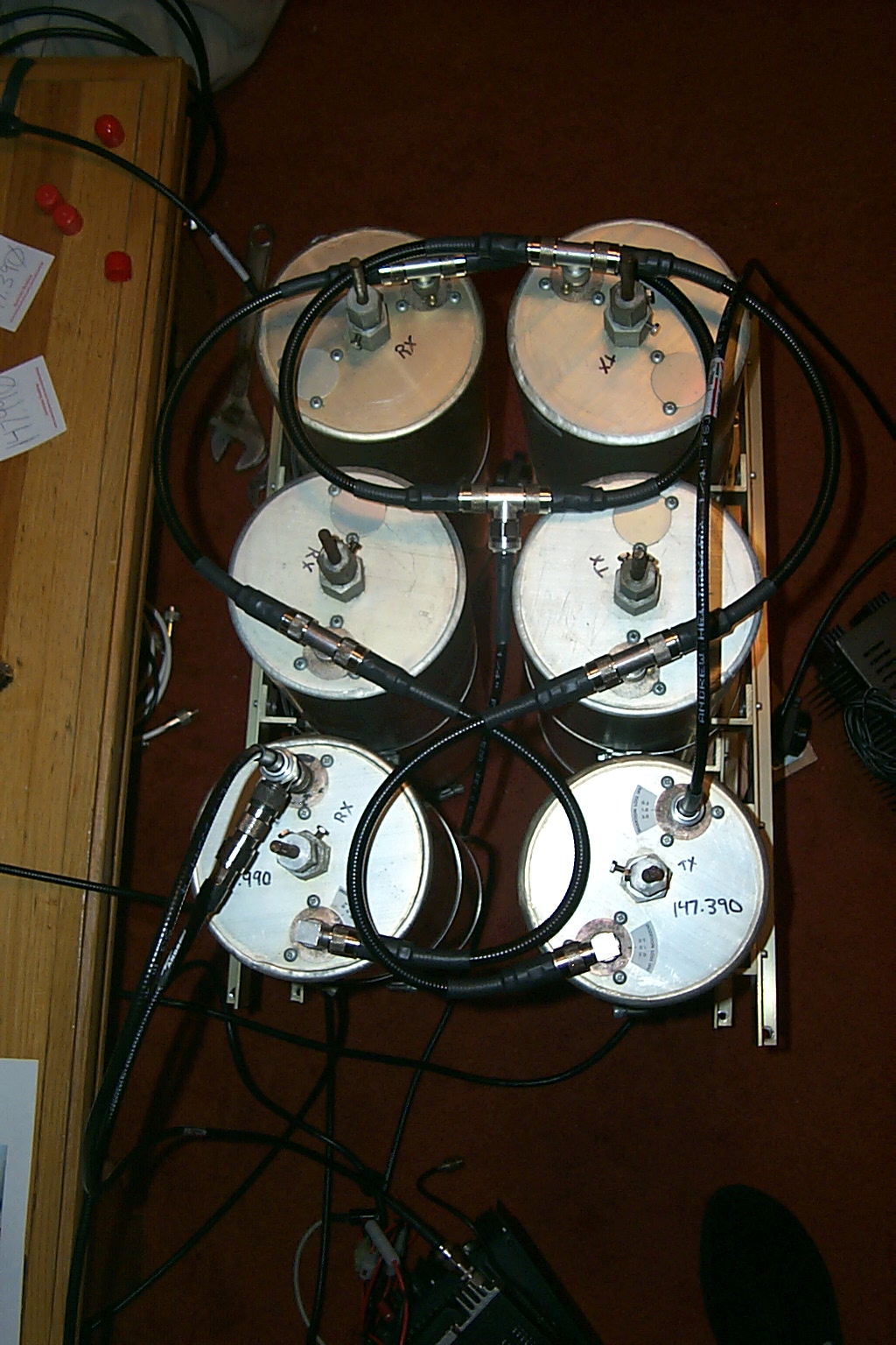
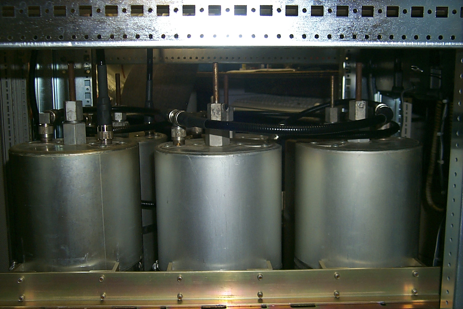
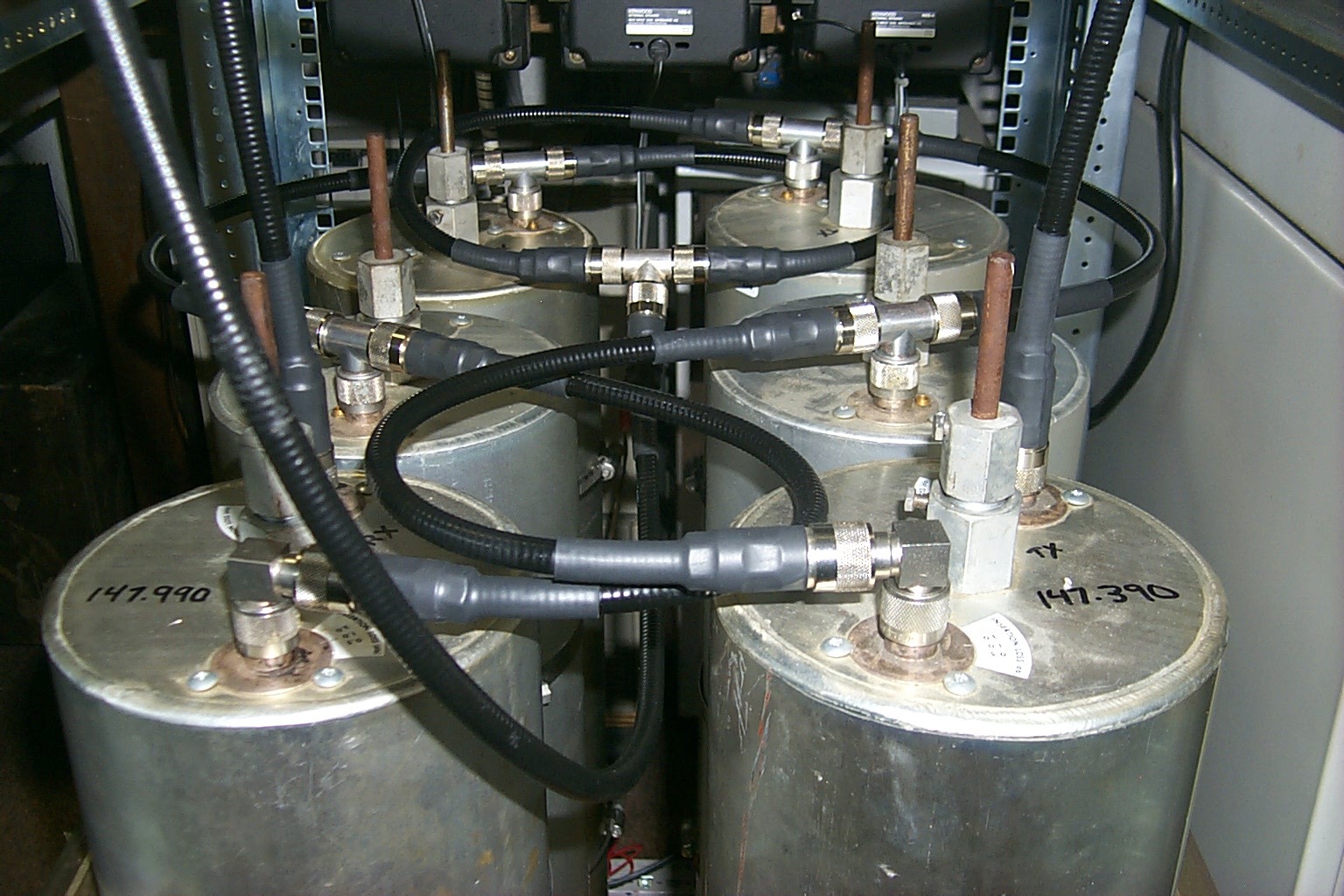
With this information in hand I asked Roland for help making the same configuration changes to the Westerly 147.390 cavities to try and improve the receivers performance. The cavities were configured with three filters on each half of the duplexer, two Bp/Br and one Bp for TX, and the same configuration for RX.
This photo shows the 147.390 duplexers original 3 x 3 configuration.
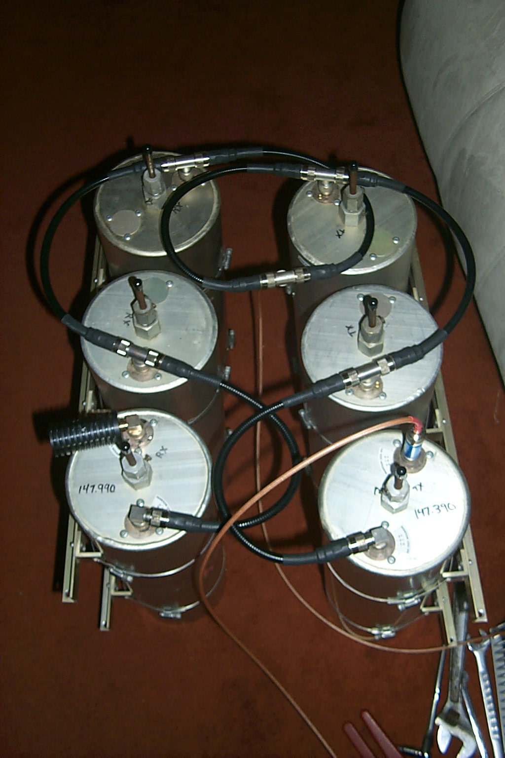
(click on images to enlarge)
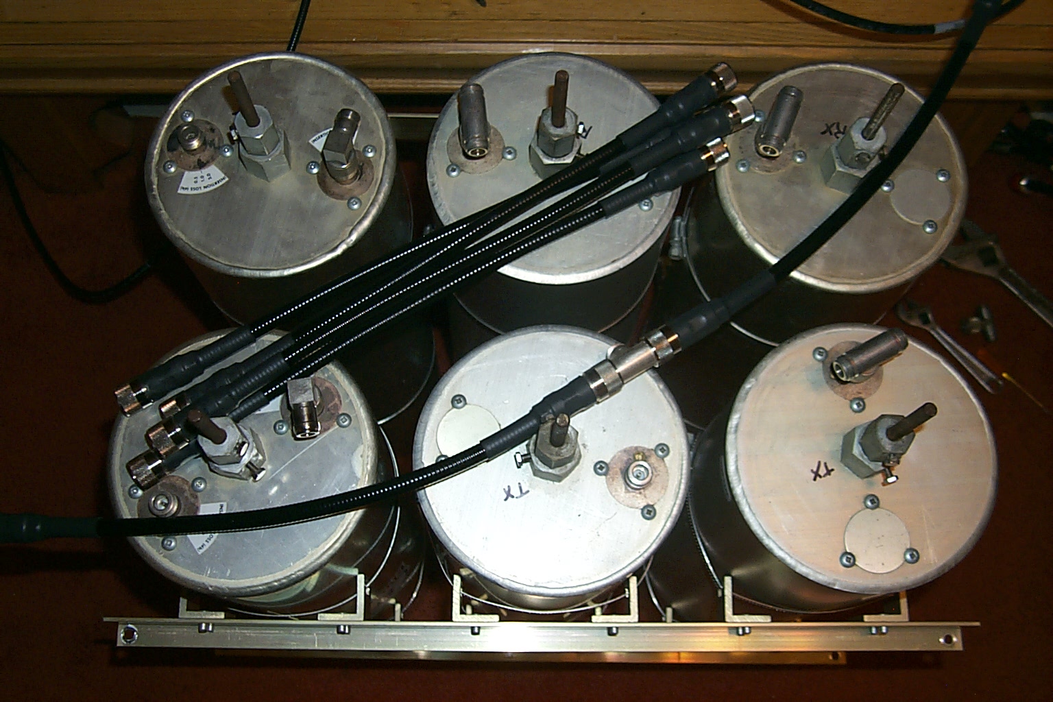
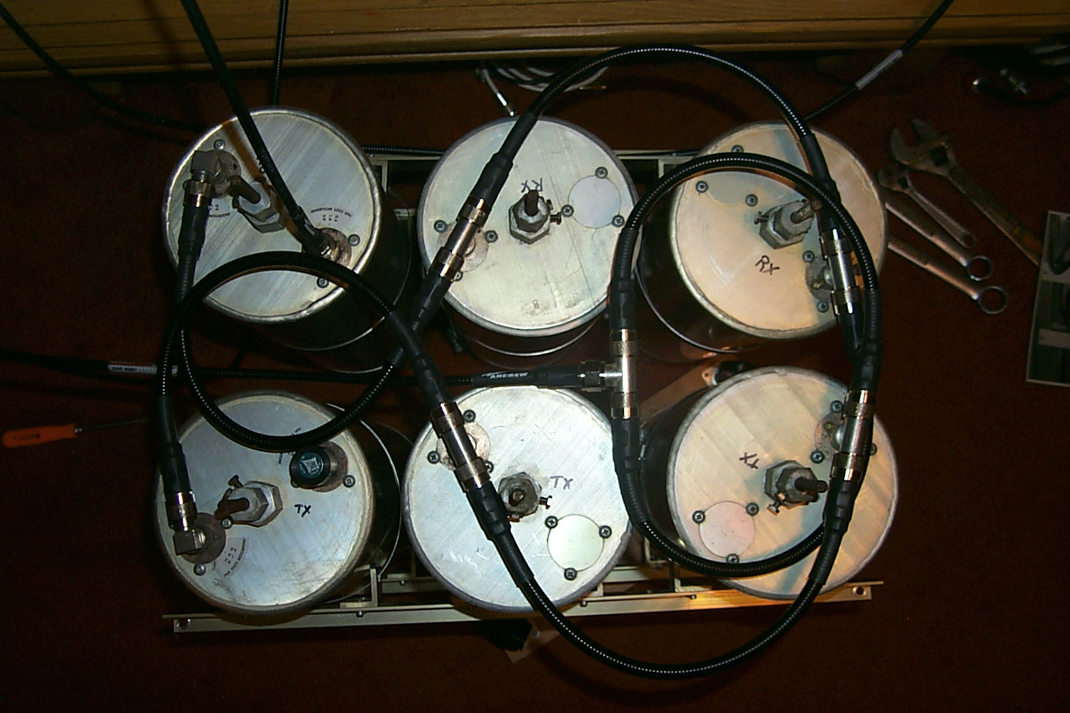
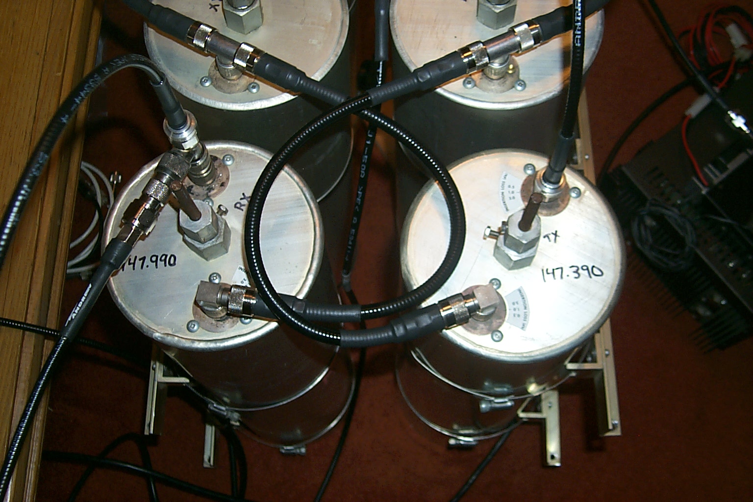
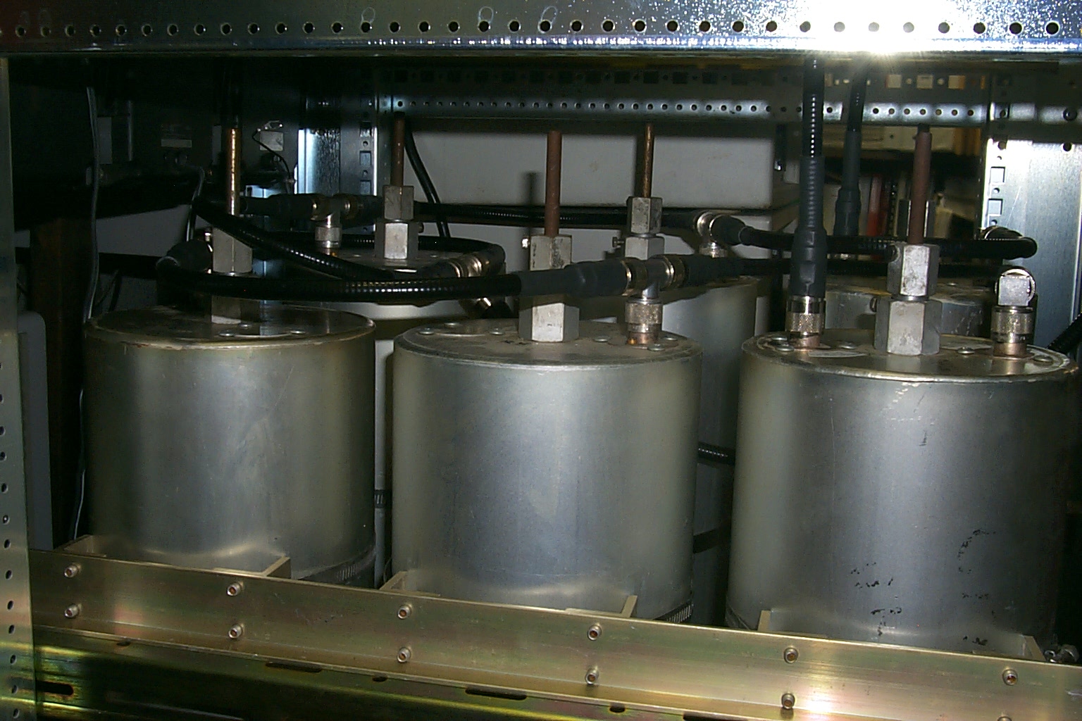
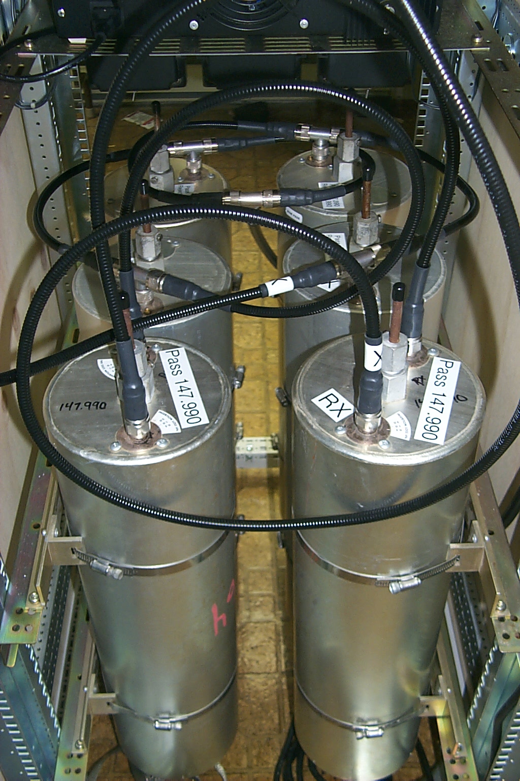
These photos shows the 147.390 duplexers new 2 x 4 configuration.
With the new jumpers installed I did a rough tune-up in the living room to get the cavities dialed in on the 147.390 / 147.990 frequency pair...
(click on images to enlarge)
After I had the cavities reconfigured with the new jumpers I brought everything back to the HAMCOW for another performance tuning session with Roland N1JOY.
(click on images to enlarge)
This diagram shows the before and after configuration with the performance improvements we were able to accomplish with the new 1/4 wave, 1/2 wave, and full wave cables.
(click on images to enlarge)
Once we have the cavities dialed in on the 147.390 / 147.990 frequency pair I loaded everything into the Big Blue beast and took it all back to the Westerly, RI site and bolted all the hardware back into the repeater rack.
(click on images to enlarge)
With the reconfigured cavities bolted back in the rack the VSWR was much better.
(click on images to enlarge)
Return to the KA1RCI Repeater Network Home Page
This page was last updated on
02/03/2010 and it has been viewed times.
Send mail to [email protected] with questions or comments about this web site.
Copyright 1995-2007 Steven M Hodell
Copyright in these pages, in the screens displaying the pages and in the information, materials and other content contained in this web site is owned by Steven M Hodell unless other wise indicated and is protected by U.S. and international copyright laws and treaties. The information, materials and other content of this web site may not be copied, displayed, distributed, downloaded, licensed, modified, published, reposted, reproduced, reused, sold, transmitted, used to create a derivative work, or otherwise used for public or commercial purposes without express written consent.