Established 1984
JAGY-146-7-EM "KA1RCI Thunder Boomer"
(click
on images to enlarge)
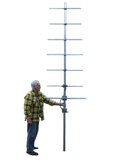
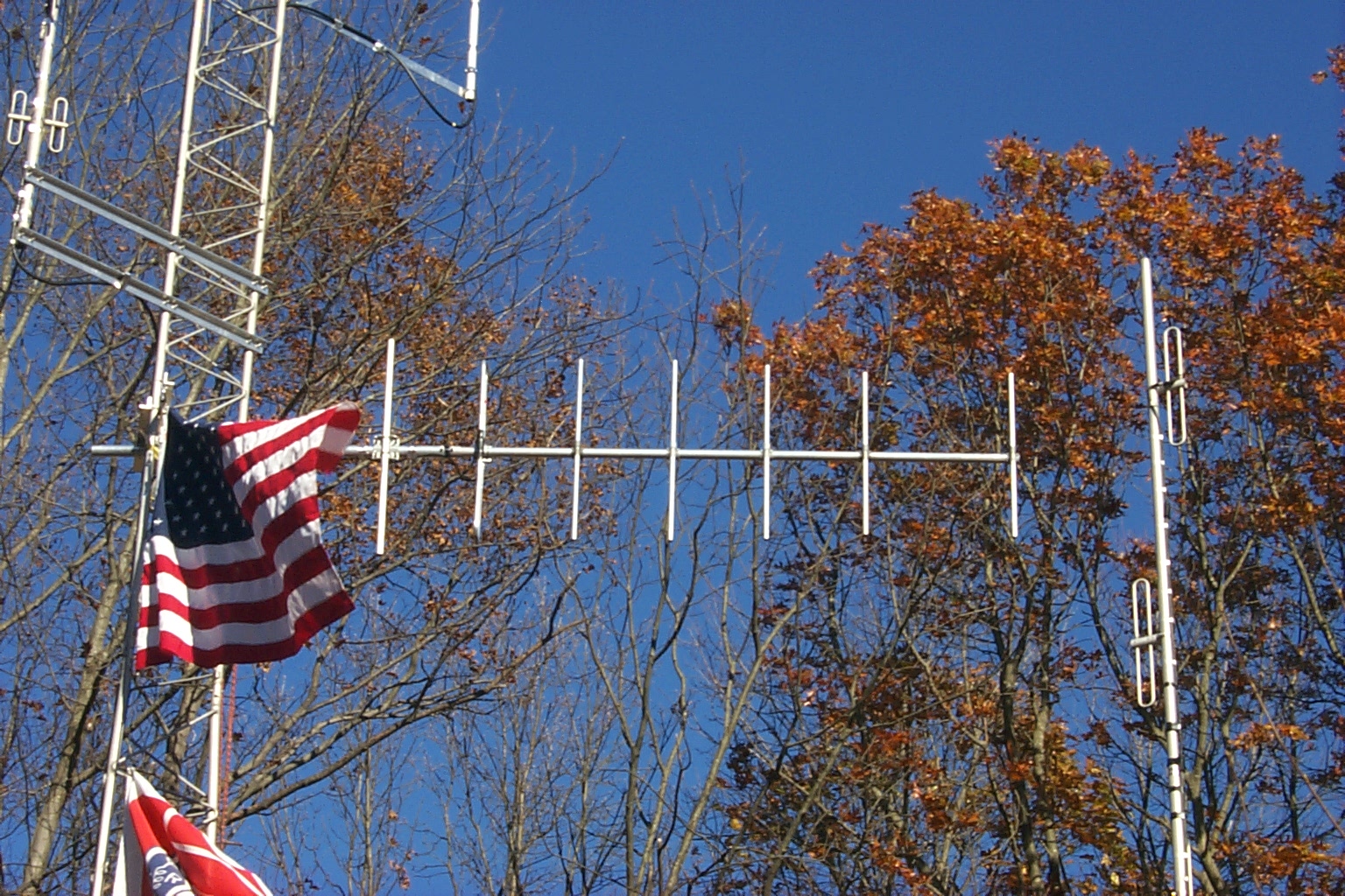
The JAGY-146-7-EM aka "The KA1RCI Thunder Boomer"
yagi antenna has been developed to meet the needs of amateur radio operators
who require a high gain, broadband, premium quality directional antenna
providing 9.5 - 10 dBd of gain with a low VSWR across the entire 144-148 MHz
frequency band. Up until 2010, JAG
Electromagnetics only made VHF yagis with up to 6-elements. However, in late
2010, KA1RCI required a rugged yagi with 7-elements in order to squeeze out
as much forward gain as possible; hence, the "Thunder Boomer", which KA1RCI
affectionately named. The JAGY-146-7-EM
antenna consists of a seven-element yagi of exceptional durability and
performance. All elements including the driven folded dipole element are
maintained at DC Ground potential for lightning protection. The JAGY-146-7-EM antenna is
suitable for mounting on the top or side of a tower or pole. No mounting
hardware is supplied with this antenna as site specific mounting hardware is
necessary with the Thunder Boomer to assure optimum performance. This Yagi
can be installed in either a vertically or horizontally polarized
orientation. A special JAG HMK kit is required when mounting for horizontal
polarization.
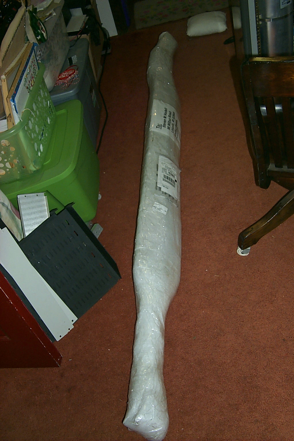
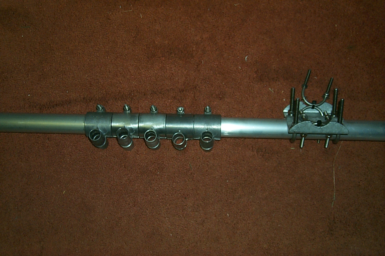
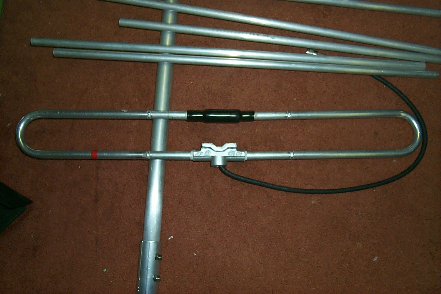
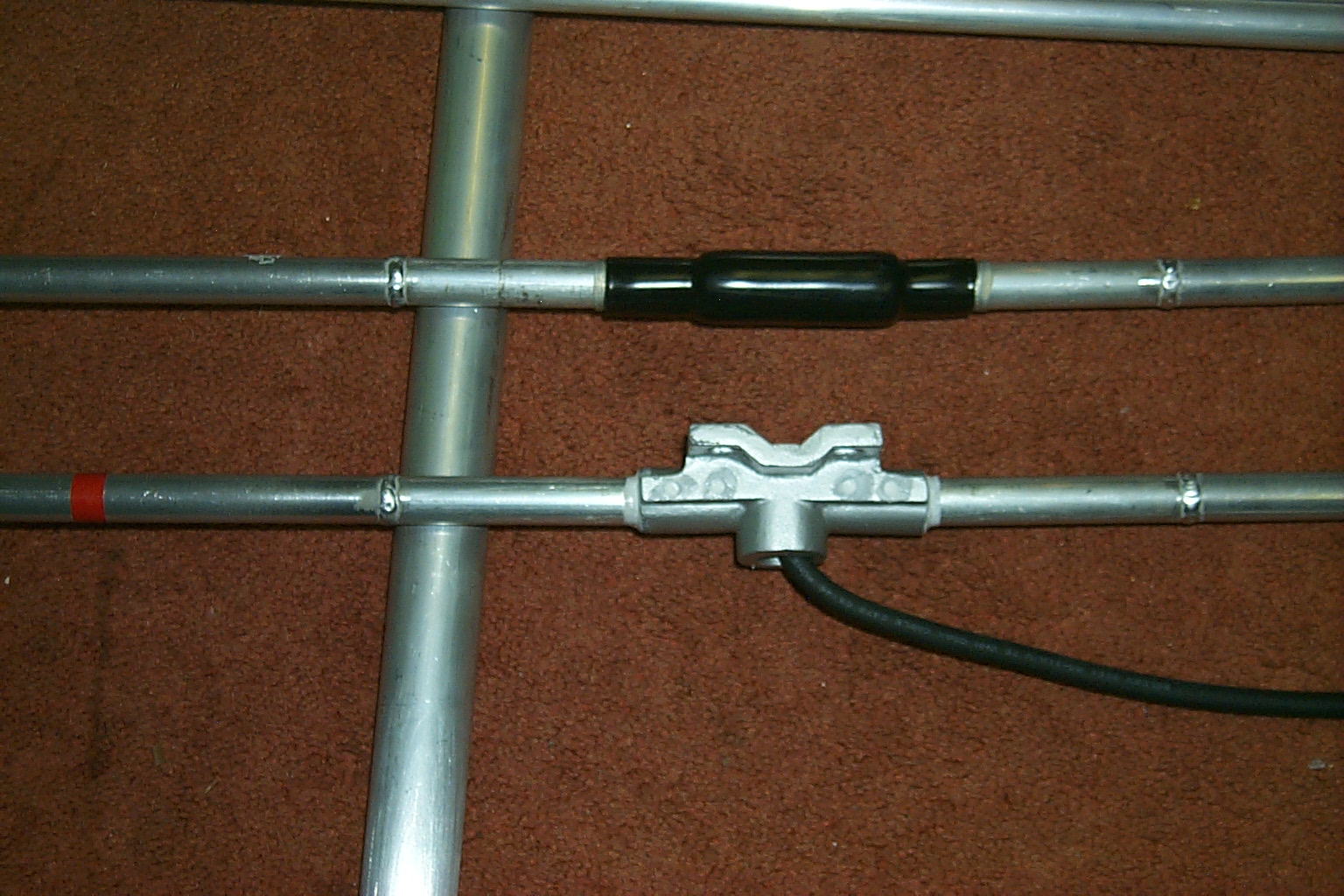
Building the Boomer
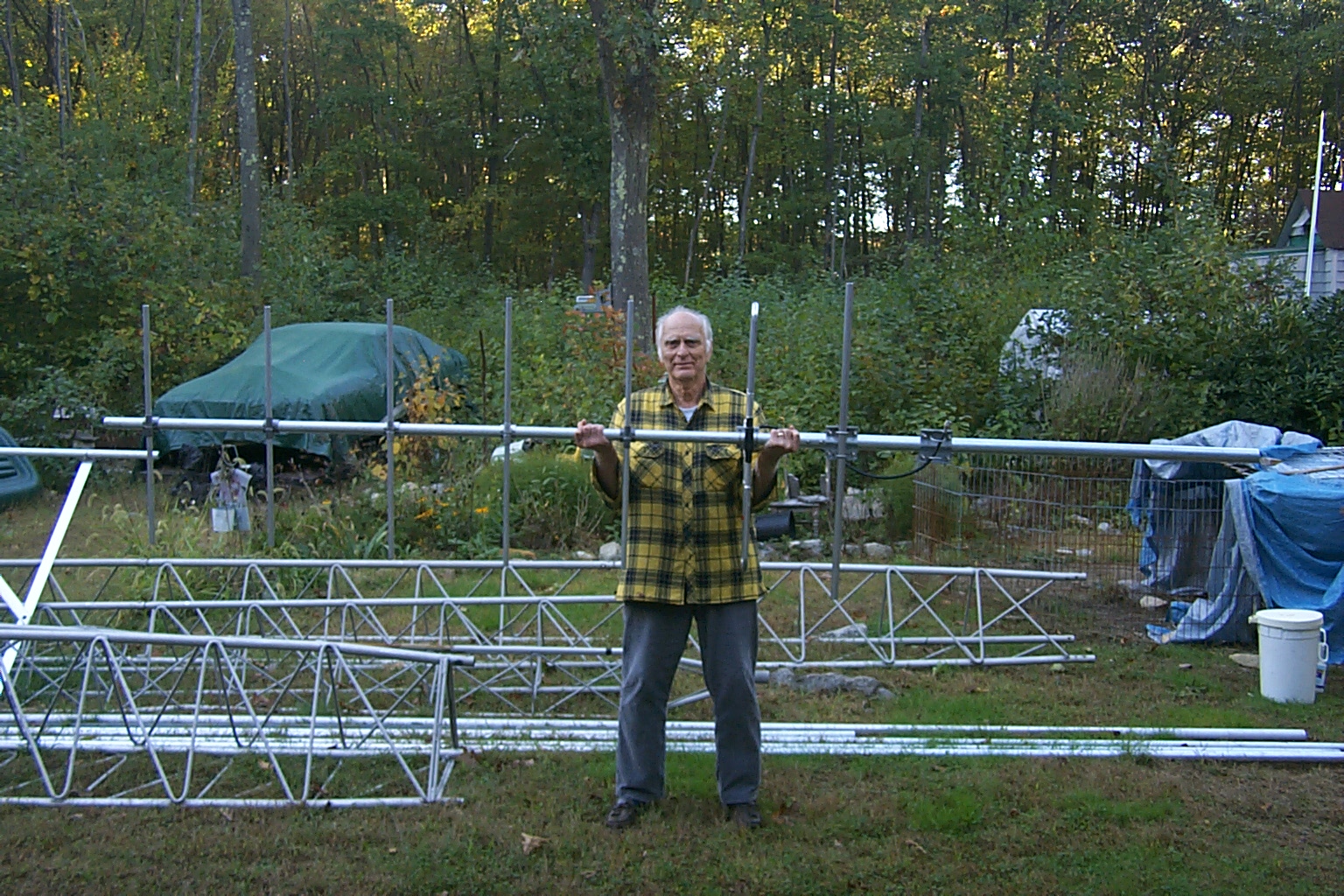
While Dad was raking up the last of the ground cover I was unpacking and building my new custom JAG 144-148 MHz seven element end mounts Yagi antenna. This antenna is very impressive and much bigger than I expected. It did not look so large in the example photo that Jag had send me several weeks ago small but I am very pleased.
(click on images to enlarge)
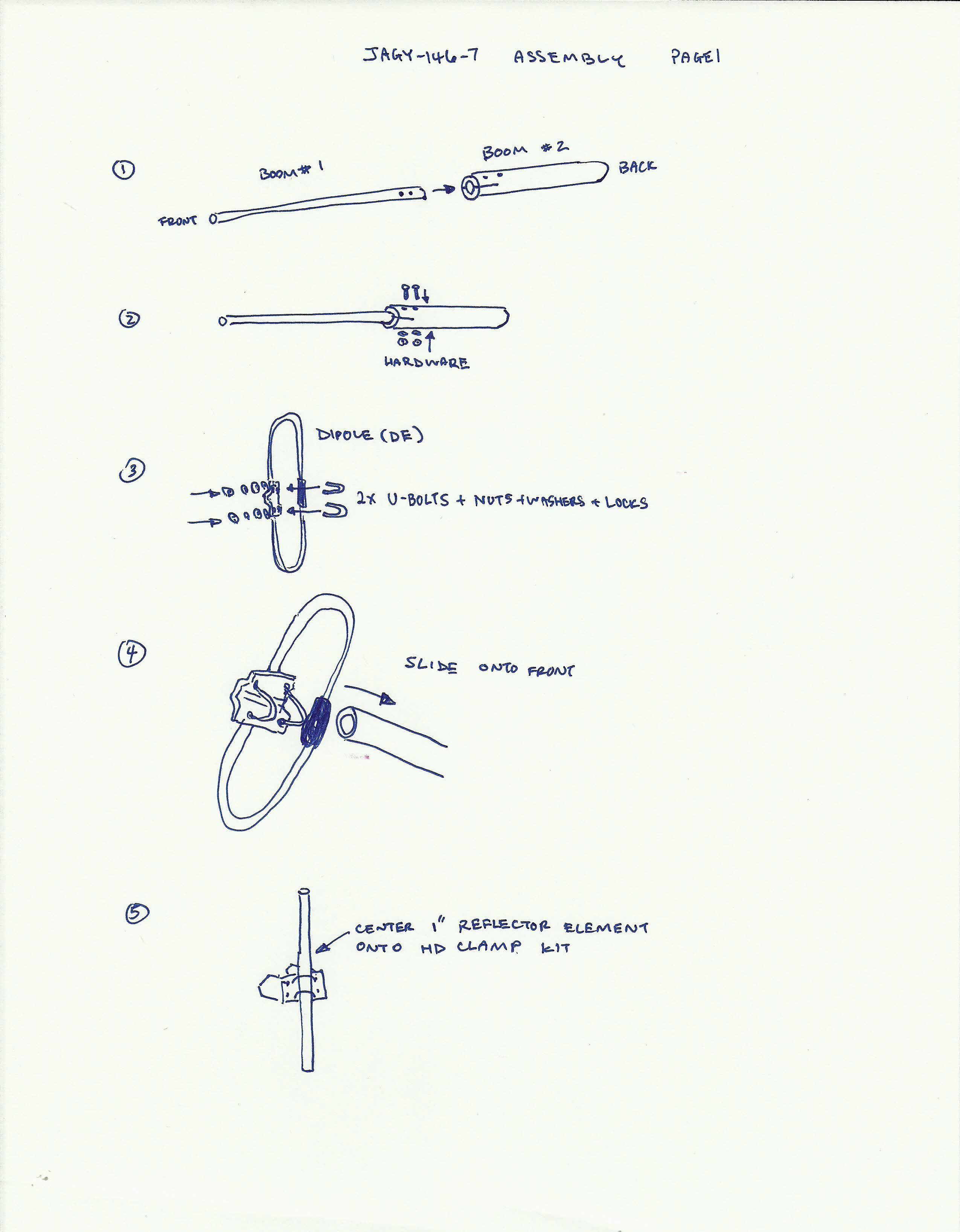
Here are the detailed, hand written, instructions that Jag sent me to assemble my new antenna.
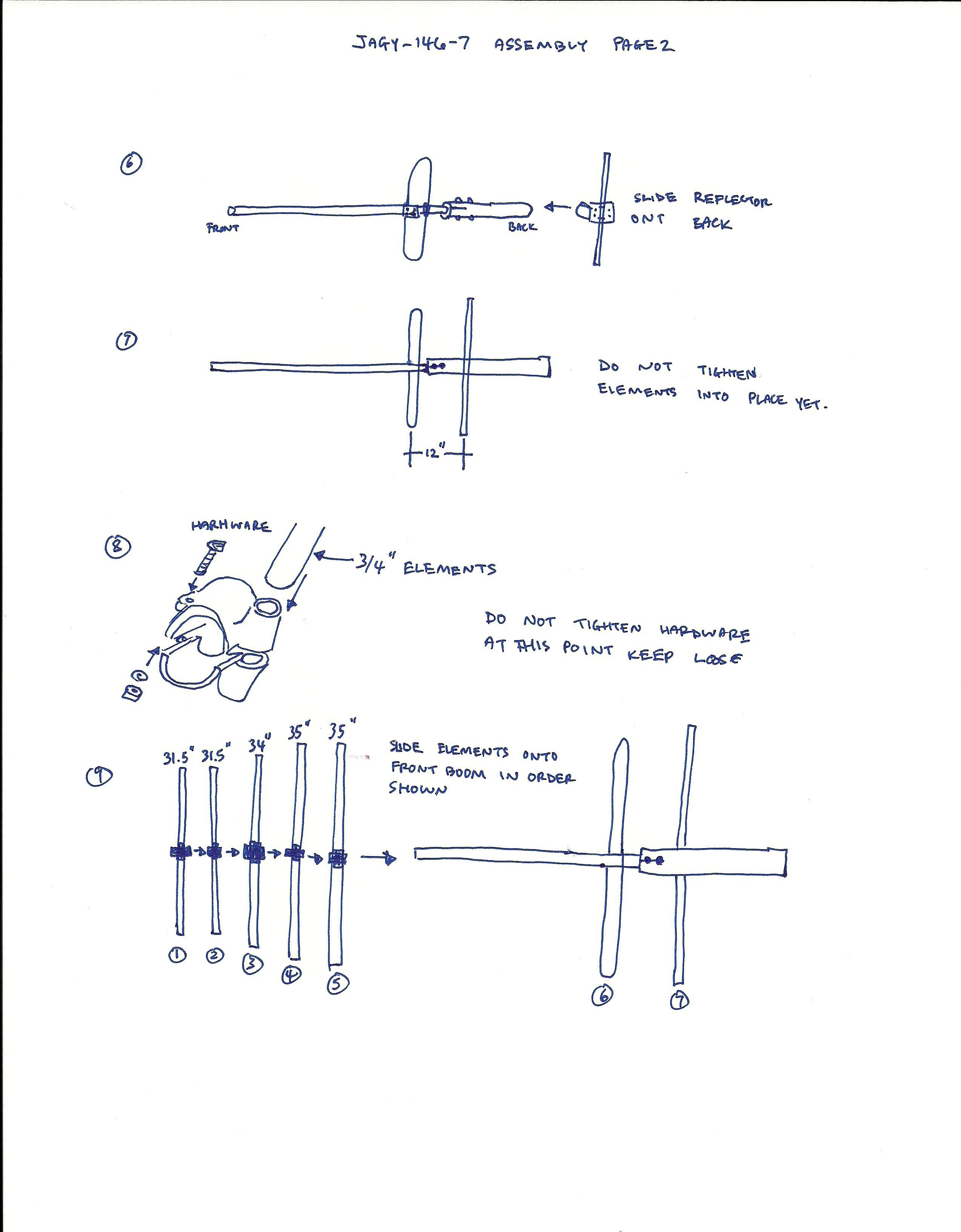
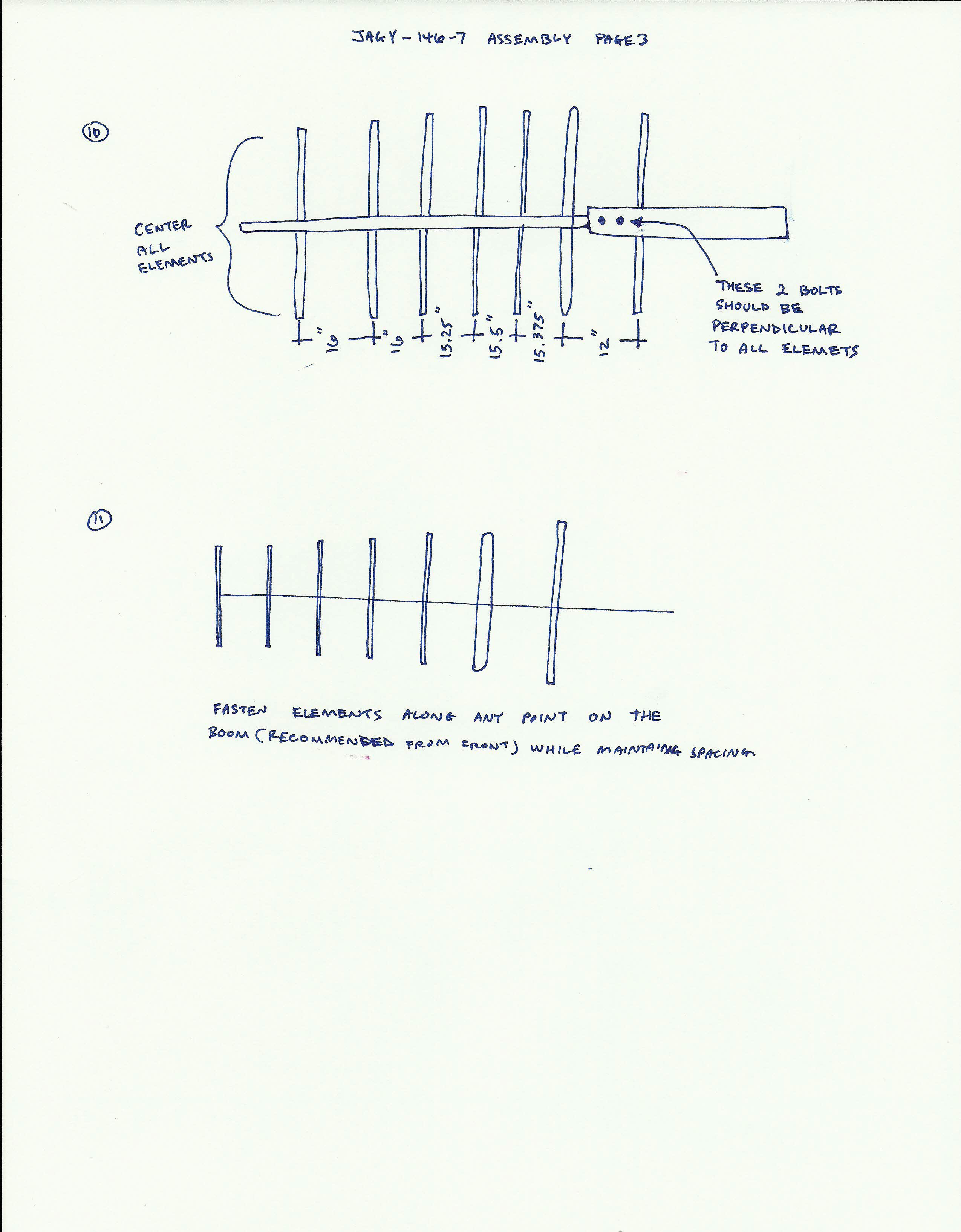
(click on images to enlarge)
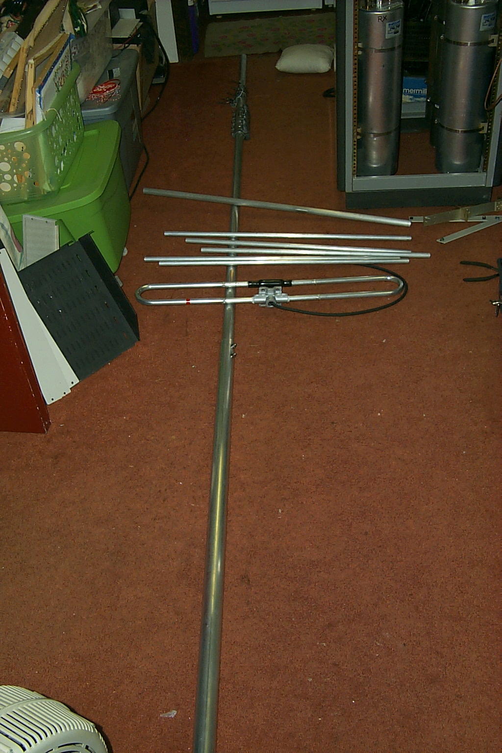
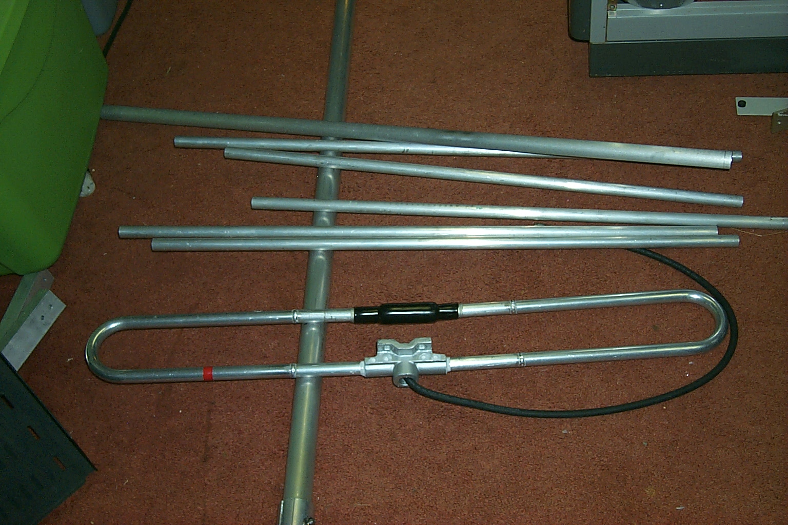
It took me a few hours to unpack and assemble the antenna and it wasn’t until after I was finished (felling a great sense of accomplishment) that I realized that I had just assembled a 13 foot long by 3 foot wide antenna on the floor of a 10 X 15 foot room!
How the hell was I going to get this thing out of the house???
After a few minutes of beating myself up for being
so blonde I was able to jockey the antenna out into the hallway, up the stairs
to the double front doors and get outside that way…
I wonder if the Chief will be able to hear me now?
(click on images to enlarge)
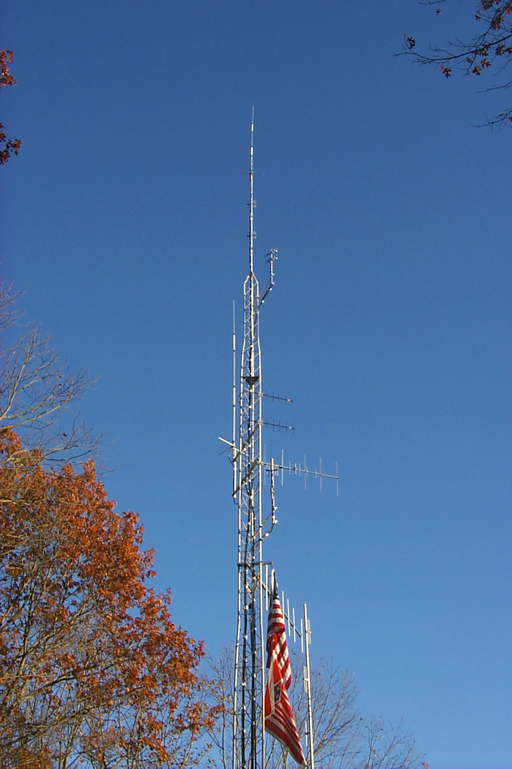
Tomorrow I hope to get started by mounting my new JAG 144-148 "Thunder Boomer" on the tower, cranking up the four sections we have assembled and performing the fine tuning adjustments for the best VSWR. Jag is on "stand-bye" waiting for Dad and I to call if we have any issues getting the new end mounted Yagi dialed in on my tower.
Monday Morning October 11th
Tuning the JAG 144-148 "Thunder Boomer"
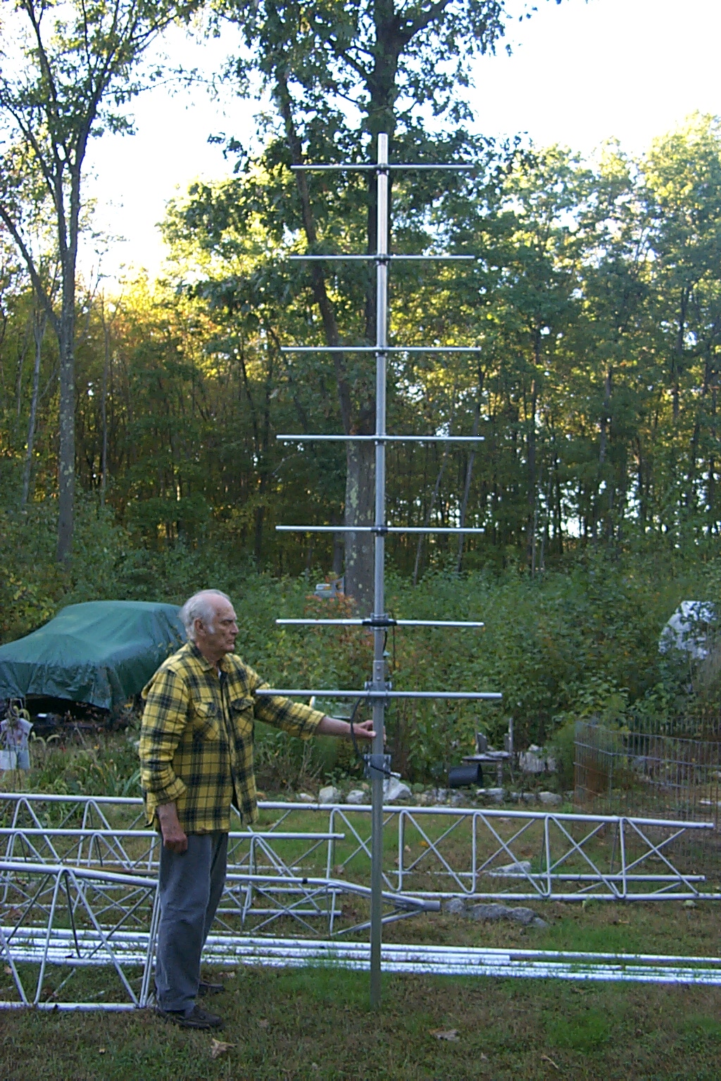
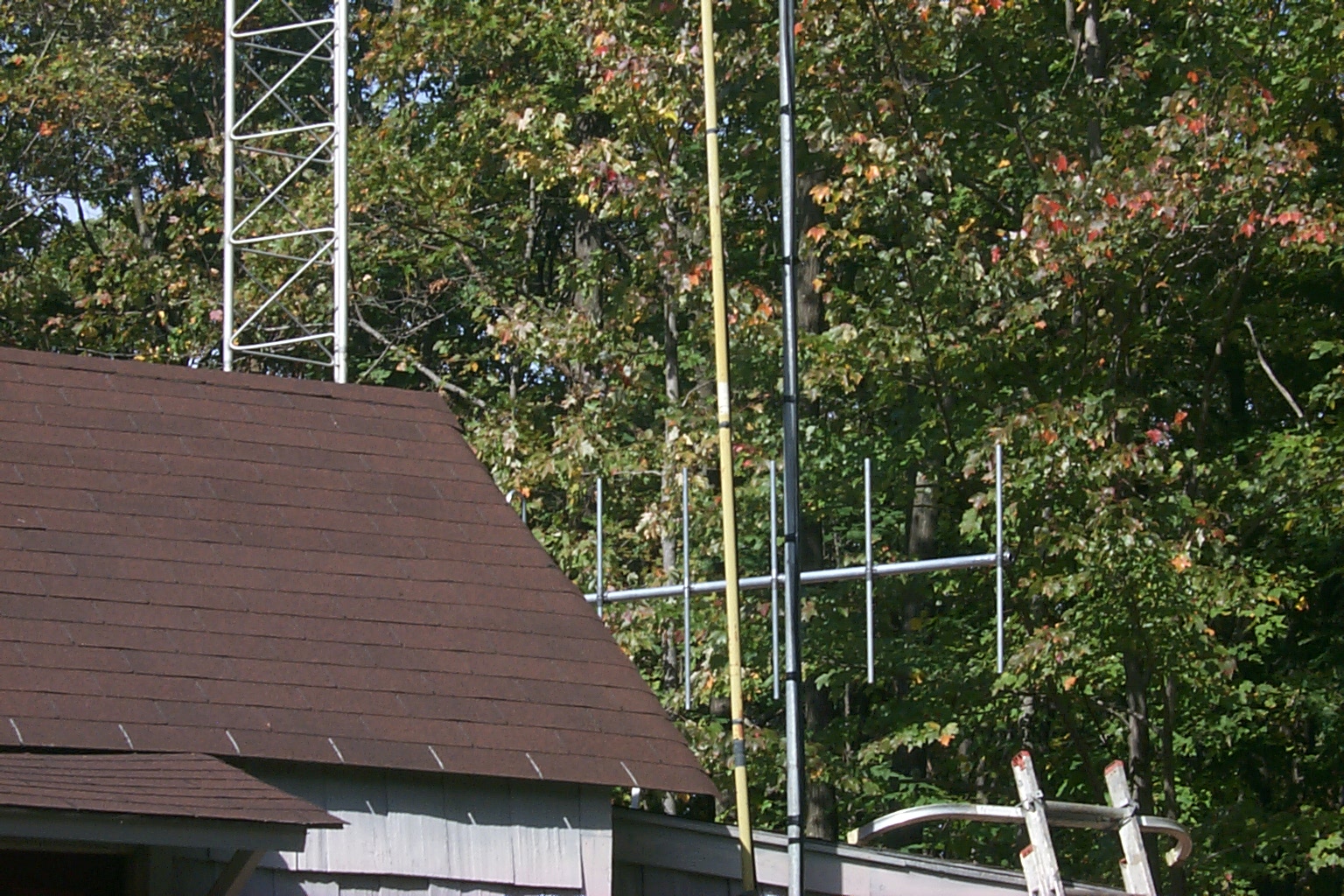
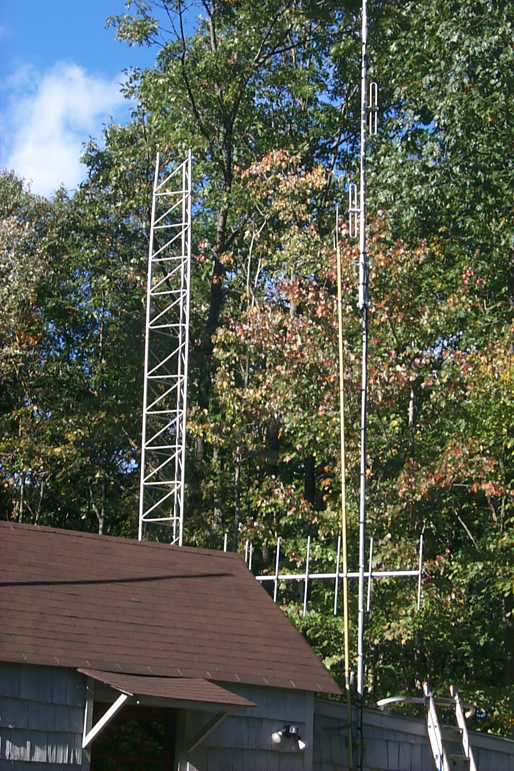
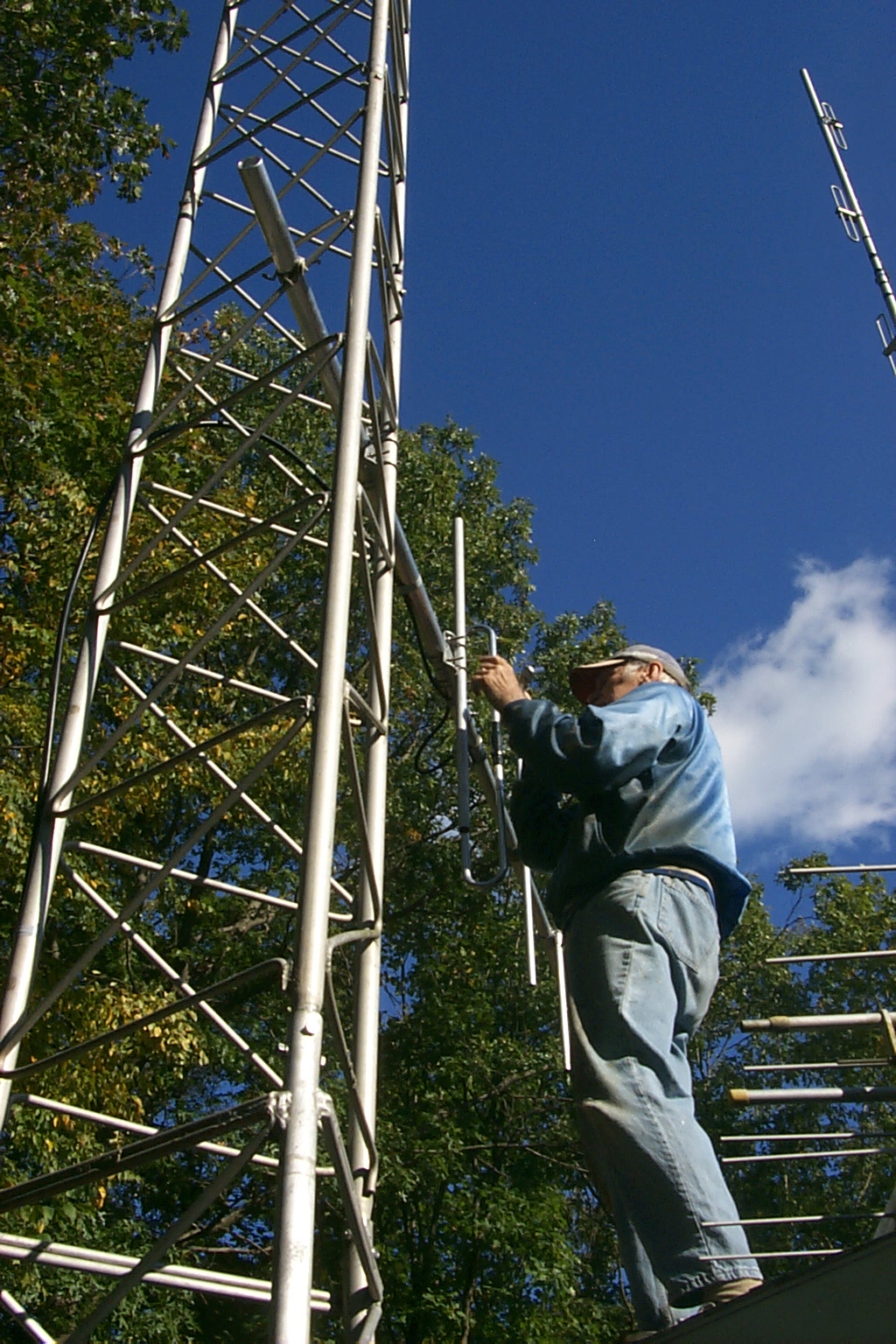
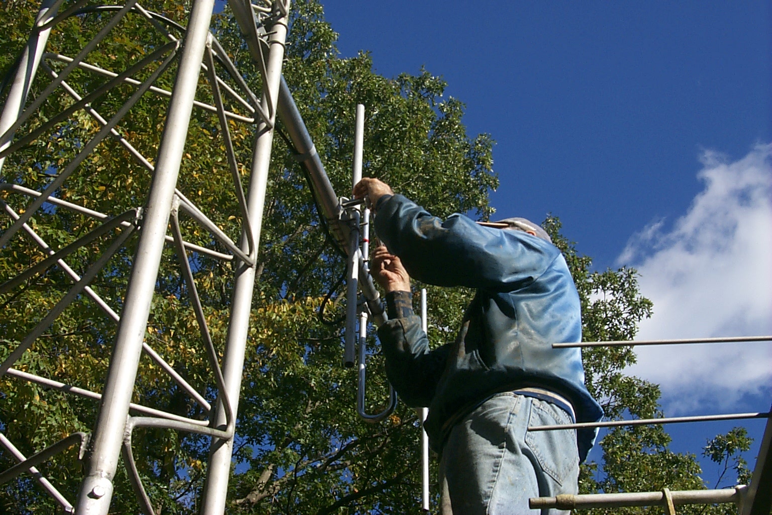
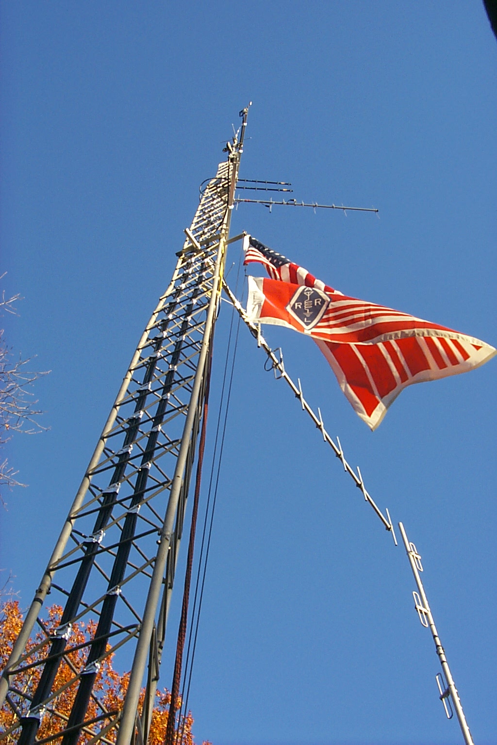
Monday morning the weather was perfect and Dad & I got an early start. We mounted the new JAG 144-148 MHz seven element end mounted Yagi on the tower and cranked the tower up so we could fine tune the new "Thunder Boomer".
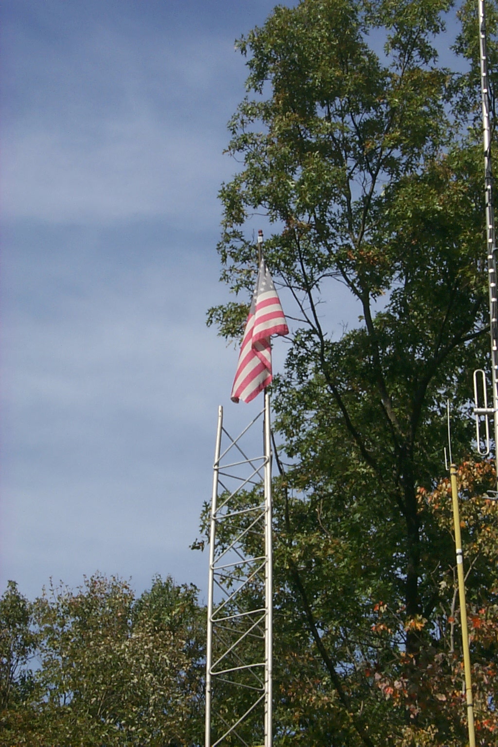
(click on images to enlarge)
We only four sections (half the tower) we are able to crank the tower up and down very easily which allowed us to work on the new JAG antenna down on the ground but crank it up for the VSWR sweeps. In the test location the antenna was only 12 feet off the ground so Dad was also able to stand on the repeater shed and make small adjustments to the various elements as well.
(click on images to enlarge)
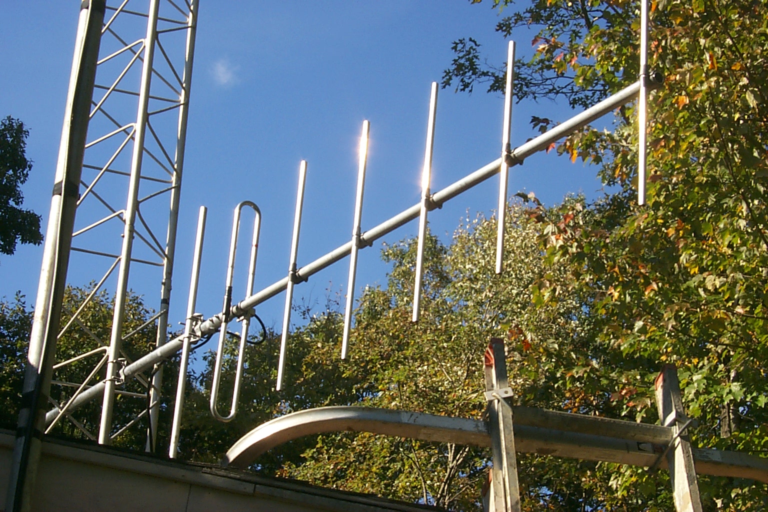
Working with Jag via email, we got the initial rough tuning by adjusting the spacing between Element No. 1 and Element No. 2 at the end of the boom and then dialed in the fine tuning matching the "Thunder Boomer" to my tower by adjusting the spacing between the Driven Element and the Reflector. In this series of VSWR Plots you can see the antenna moving towards the desired frequency as we made the adjustments.
(click on images to enlarge)
This is the last VSWR Sweep of the antenna in the test position; I will post the results of VSWR measurements when the antenna in mounted in the final position and the whole tower has been cranked back up.
| FREQ | Watts Fwd | Watts Rev | VSWR |
| 143.50 | 40 | 4.4 | 1.99 |
| 144.00 | 50 | 4.8 | 1.90 |
| 144.50 | 70 | 5 | 1.73 |
| 145.00 | 80 | 4 | 1.58 |
| 145.50 | 82 | 2.6 | 1.43 |
| 146.00 | 86 | 1.2 | 1.27 |
| 146.50 | 86 | 0.5 | 1.17 |
| 147.00 | 84 | 0.6 | 1.18 |
| 147.50 | 82 | 1.5 | 1.31 |
| 148.00 | 80 | 3 | 1.48 |
| 148.50 | 80 | 5 | 1.67 |
In the first three plots above the
boomer was mounted on the tower at approximately 12 feet above the ground so
Dad could stand on the repeater shed roof and move the various elements. In
the final configuration (third adjustment) we had the end element out 24
inches and the back reflector 21 inches off the face of the tower. That plot
look real good to me and I knew that when we mounted it on the tower in the
final location I could move that back spacing out from 21 inched to 24
inches.
Sunday Evening October 21st
Testing the JAG 144-148 "Thunder Boomer" on the tower
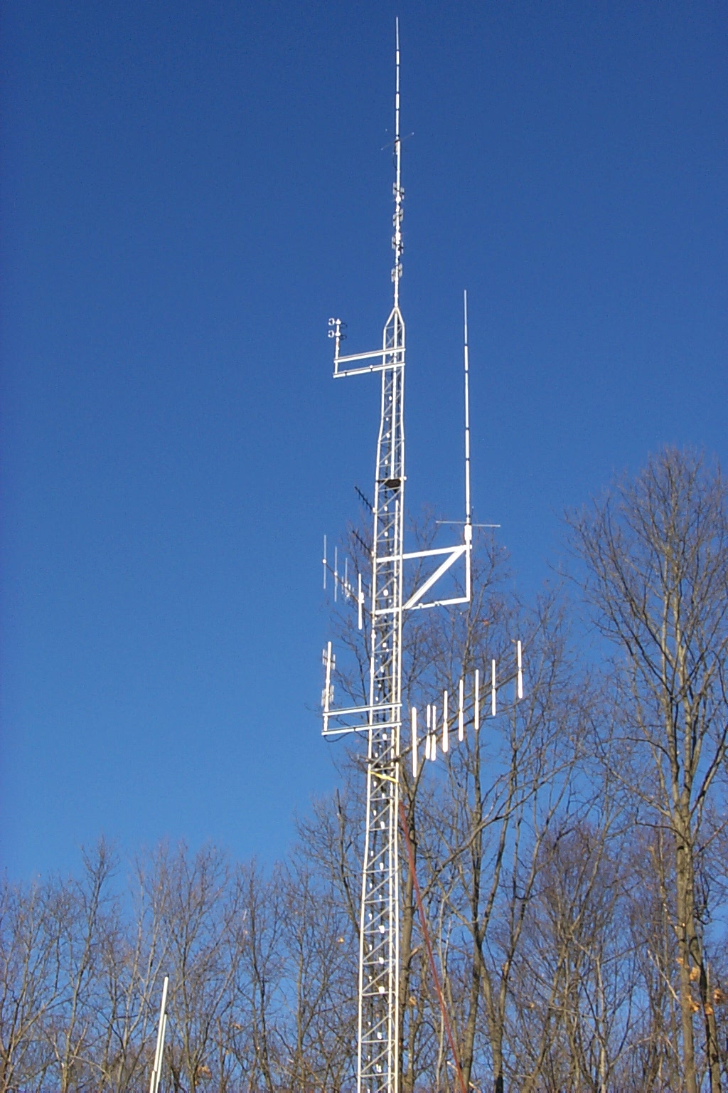
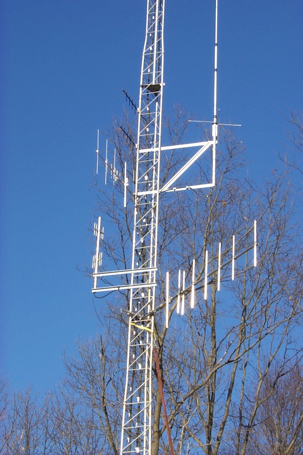
These next two plots below are with the Thunder Boomer in the final mounting
position on the tower at 33 feet above the ground with the back reflector 24
inched off the face of the tower and the front element also spaced at 24
inches. The difference in these last two plots is the 220 MHz dipole array
that was directly in front of the boomer about 21 inches away.
| FREQ | Watts Fwd | Watts Rev | VSWR |
| 144.00 | 50 | 8.6 | 2.42 |
| 144.50 | 52 | 7 | 2.16 |
| 145.00 | 48 | 5 | 1.95 |
| 145.50 | 42 | 3 | 1.73 |
| 146.00 | 38 | 1.6 | 1.52 |
| 146.50 | 38 | 0.72 | 1.32 |
| 147.00 | 40 | 0.4 | 1.22 |
| 147.50 | 42 | 0.7 | 1.30 |
| 148.00 | 44 | 1.6 | 1.47 |
Once we had the 224.040 repeater moved over to the new antenna at the very top of the tower we were able to remove the temporary 220 MHz dipole array that was directly in front of the new JAG "KA1RCI Thunder Boomer"
The final VSWR sweep on my desired
frequency of 147.000 MHz
| FREQ | Watts Fwd | Watts Rev | VSWR |
| 144.00 | 36 | 2.6 | 1.74 |
| 144.50 | 38 | 2.1 | 1.61 |
| 145.00 | 40 | 1.6 | 1.50 |
| 145.50 | 44 | 1 | 1.36 |
| 146.00 | 44 | 0.48 | 1.23 |
| 146.50 | 44 | 0.22 | 1.15 |
| 147.00 | 44 | 0.18 | 1.14 |
| 147.50 | 45 | 0.32 | 1.18 |
| 148.00 | 46 | 0.82 | 1.31 |
You can order your own JAG Thunder Boomer from JAG Electromagnetics
Back to Tower History Home Page
Return to the KA1RCI Repeater Network Home Page
This page was last updated on
02/13/2011 and it has been viewed times.
Send mail to [email protected] with questions or comments about this web site.
Copyright 1995-2011 Steven M Hodell
Copyright in these pages, in the screens displaying the pages and in the information, materials and other content contained in this web site is owned by Steven M Hodell unless other wise indicated and is protected by U.S. and international copyright laws and treaties. The information, materials and other content of this web site may not be copied, displayed, distributed, downloaded, licensed, modified, published, reposted, reproduced, reused, sold, transmitted, used to create a derivative work, or otherwise used for public or commercial purposes without express written consent.