 The KA1RCI Repeater Network
146.625 / 146.025 with PL 67.0 - Established 2002
North Providence - Rhode Island
Trustee - K1RSR
Saturday morning August 30th at 8:00 am ET the Legacy K1RSR analog repeater went back on the air at the new site in North Providence.
The original hardware build by John K1JI
John K1JI built the original repeater in 2002 using a MICOR 110 watt turned down to about 50 watts. It had a serious muffin fan on continuous mounted to the MICOR heat sink right where the finials were mounted. The power supply was a 25/35 amp analog with a serious muffin fan right on the heat sink which never ran it over around 18 amps. The duplexer was a hybrid ring type manufactured by Sinclair.
John also built a custom gated CTCSS circuit that would only encode a tone on the repeater transmitter when the repeater receiver heard one. That allowed users to use cross-band repeat set-ups. John did the same type thing with the W1AQ 147.330 machine so that IRLP network won't hear IDs or beeps, just the mobile transmitting.
Changing of the guard...
In January 2007 the K1RSR license became invalid when the trustee Chris N1RWX let his amateur radio license expire. I contacted Chris to assist in getting his license renewed however he was no longer interested in the hobby and did not want to renew his license, so I worked with Perry Green at the ARRL Headquarters, and we were able to transfer the license to Scott N1RWW correcting the expired license issue. In June of 2010 Scott decided that he no longer wanted to be the trustee of the K1RSR license so it was transferred to Steve KA1RCI. Then in the March of 2011 when the original hardware that John K1JI had built disappeared under mysterious circumstances, Scott N1RWW asked me to build a new repeater.
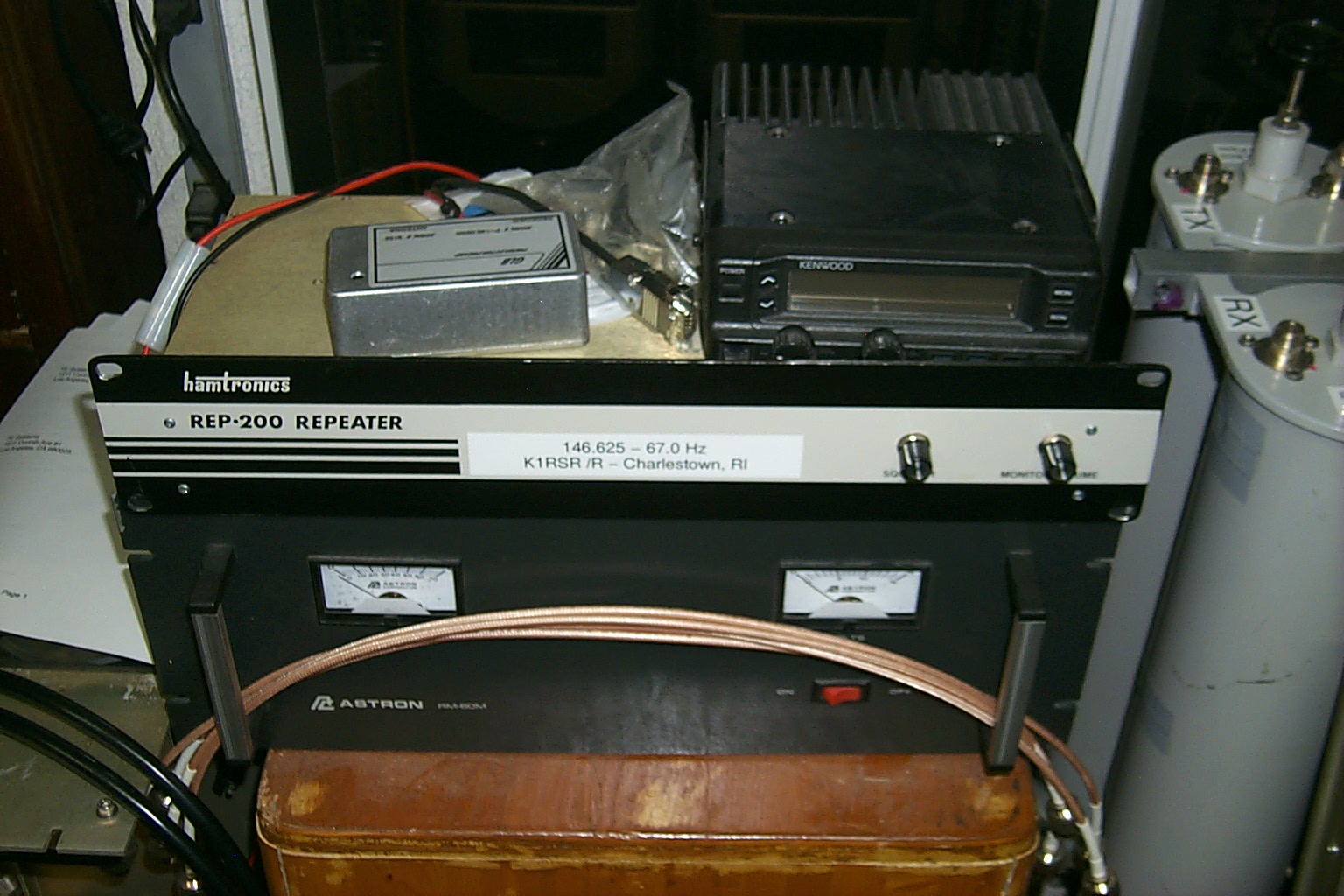
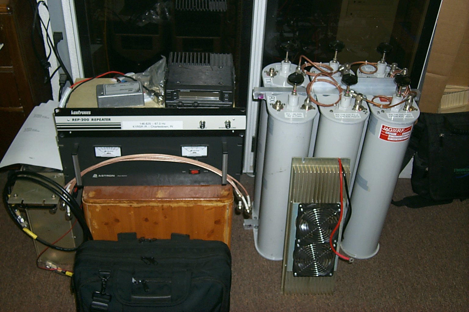
I had a temporary split site 146.625 repeater online in less than 24 hours and started the hunt for hardware to build a new repeater.
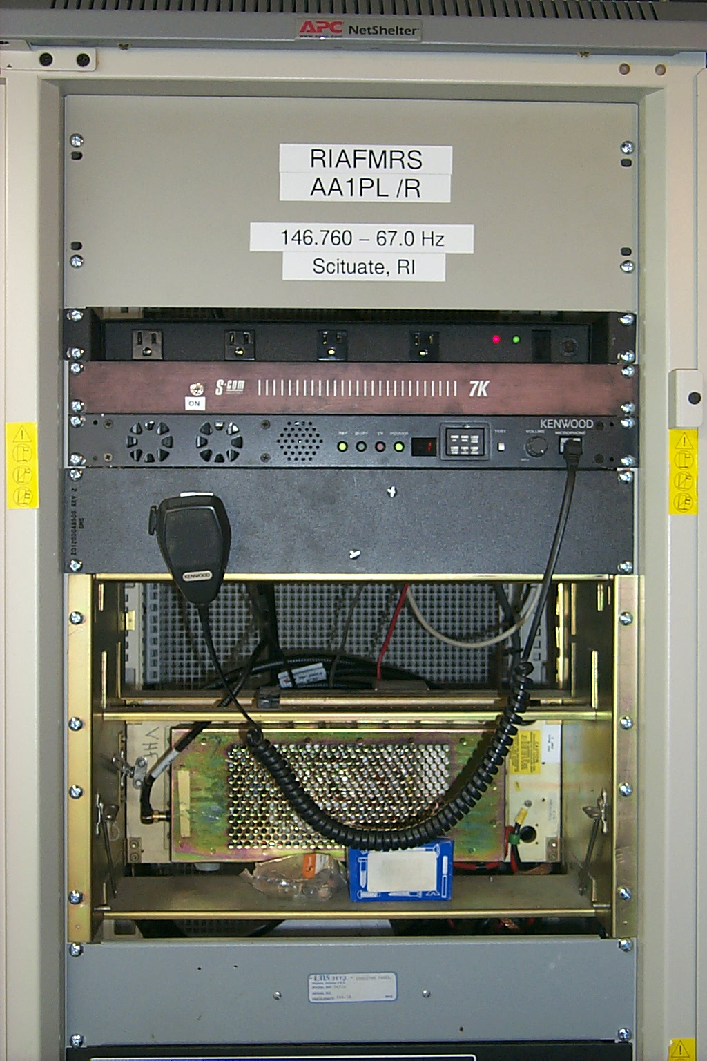
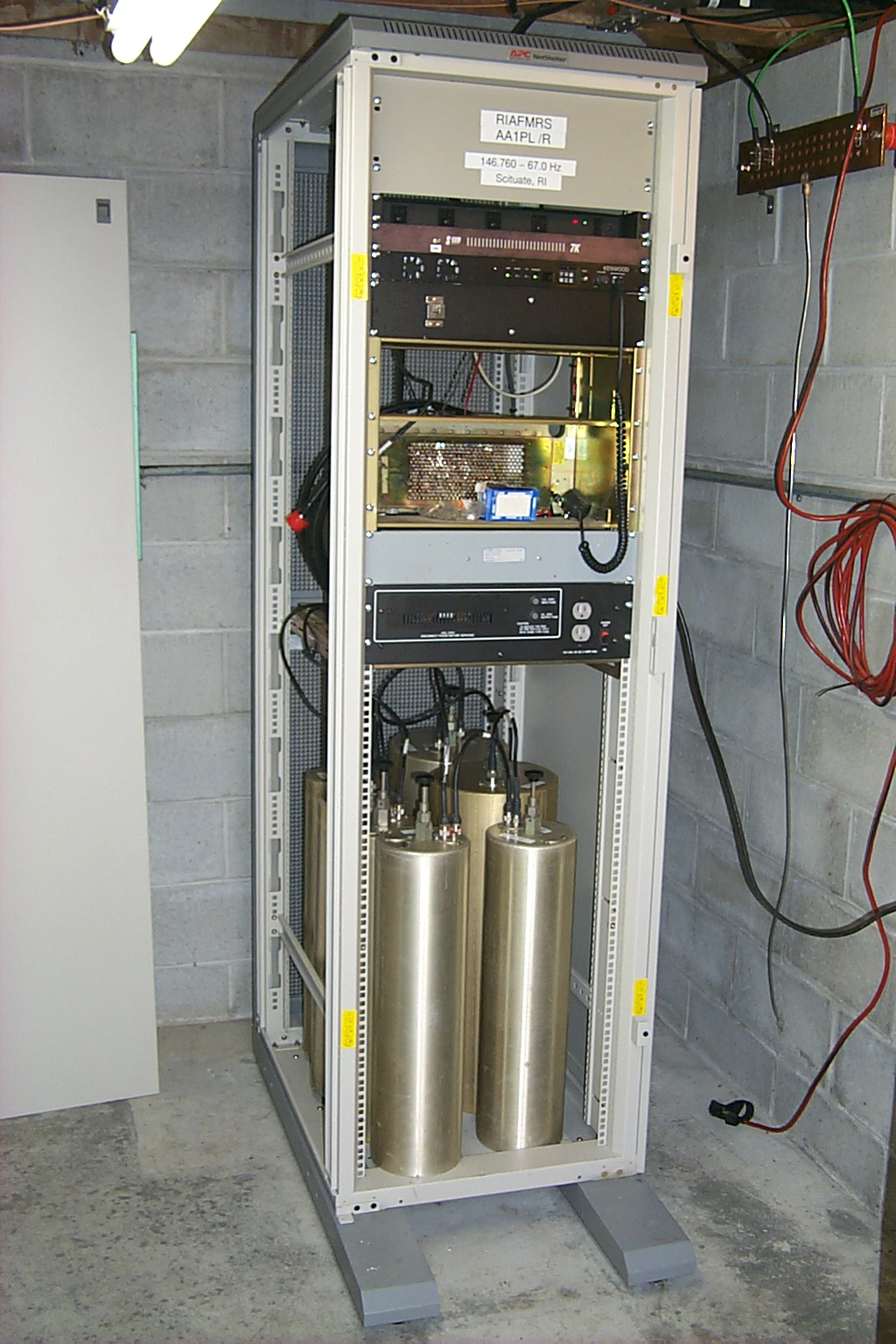
The temporary hardware on the air in 2011
Collecting all the parts...
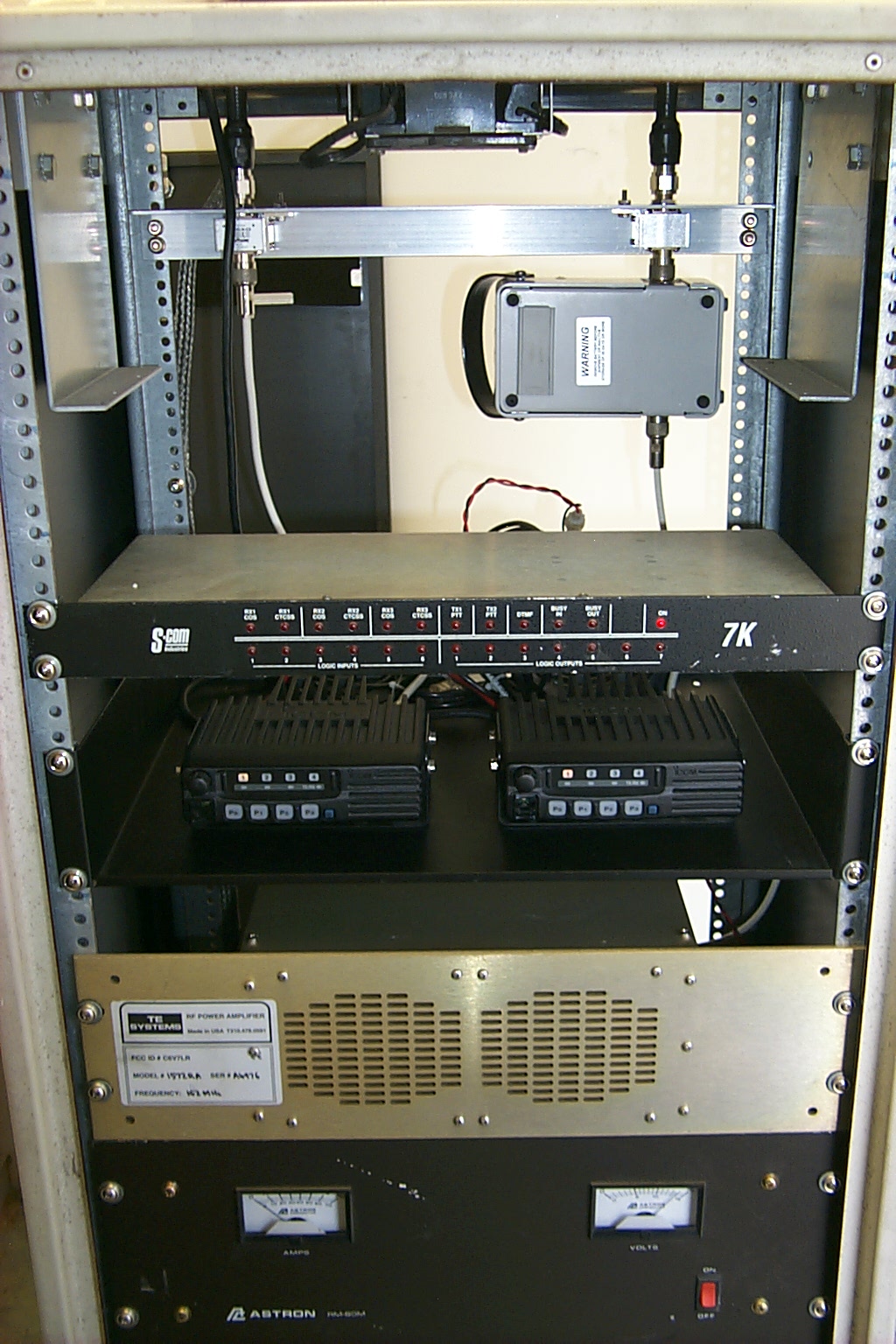
First I started collecting the necessary hardware, RF deck, Link Radio, Controller, Power Amplifier, Receive Preselector / Preamp, Power Supply, Rack Cabinet, and all the other fun stuff you need to build a big box that goes BEEP!
I was able to find everything that I needed in the spare parts pile, one of the benefits of having so many repeaters is there are always "extra" parts!
The RF deck and GLB Preselector were originally purchased in 1992, I would just need to change the frequencies and retune the hardware. I had dozens of Kenwood TK-30 series radios that could be used for the link radio. The RC-210 controller that I ended up using was purchase in 2004 which I had replaced with a new S-Com 7330 controller. The filter cavities for the duplexer had been purchased back in 1987 or 1988 for the 145.170 repeater which I upgraded to a larger Sinclair duplexer in 2011.
It turns out that I had everything needed for this project sitting in storage.
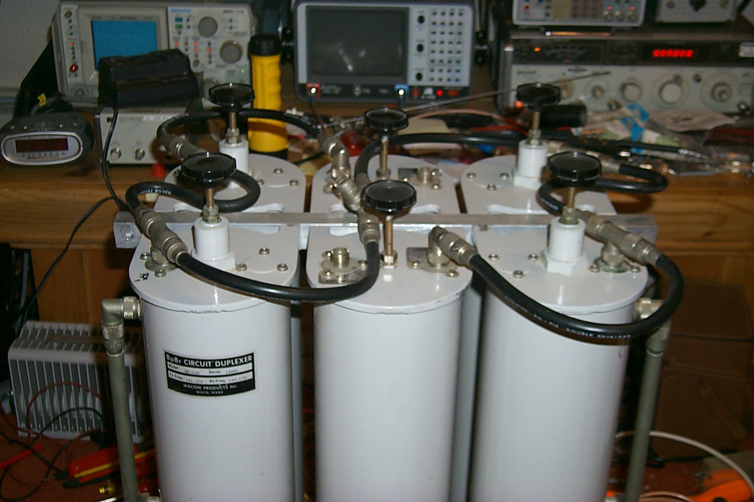
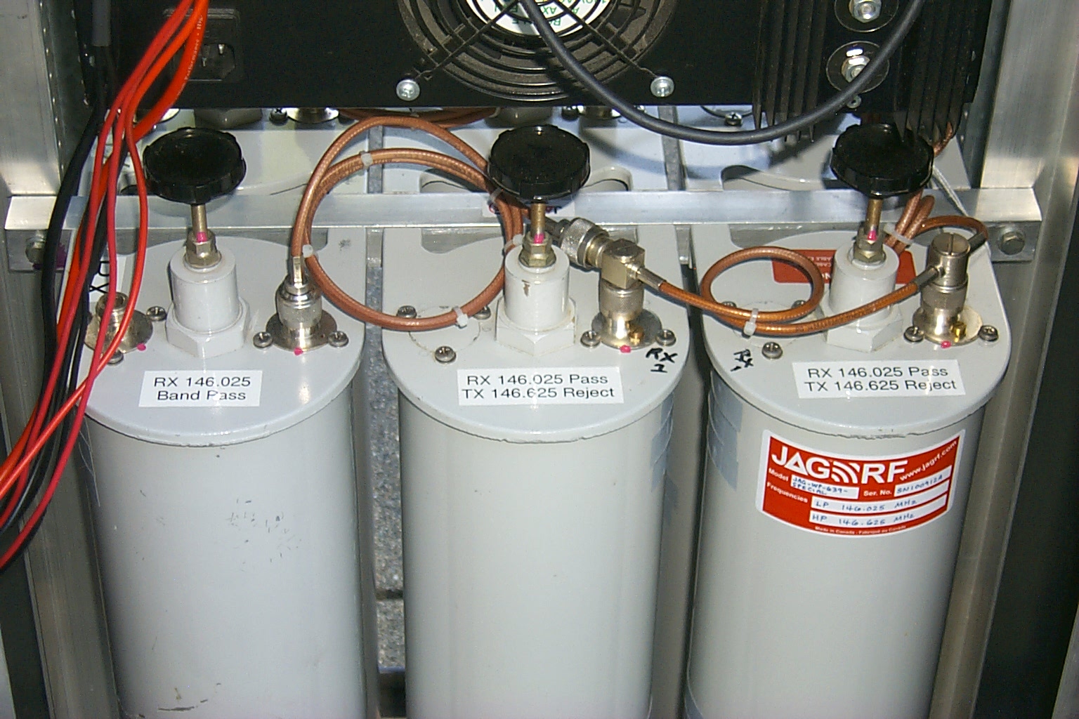
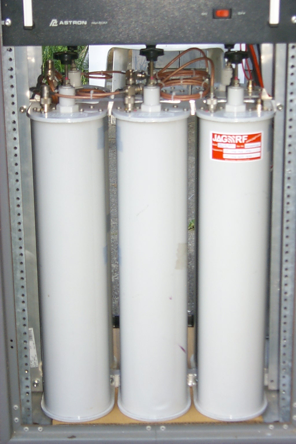
Building the duplexer...
I decided to use the old Wacom cavities that I had replaced several years ago from the 145.170 repeater. These cavities originally had SO-239 connectors and the external side tube for tuning the reject notches. After removing the external reject tubes I covered the holes with two layers of copper foil tape and then covered the copper foil with gray electrical tape to protect the foil.
(click on images to enlarge)
Lets get loopy!
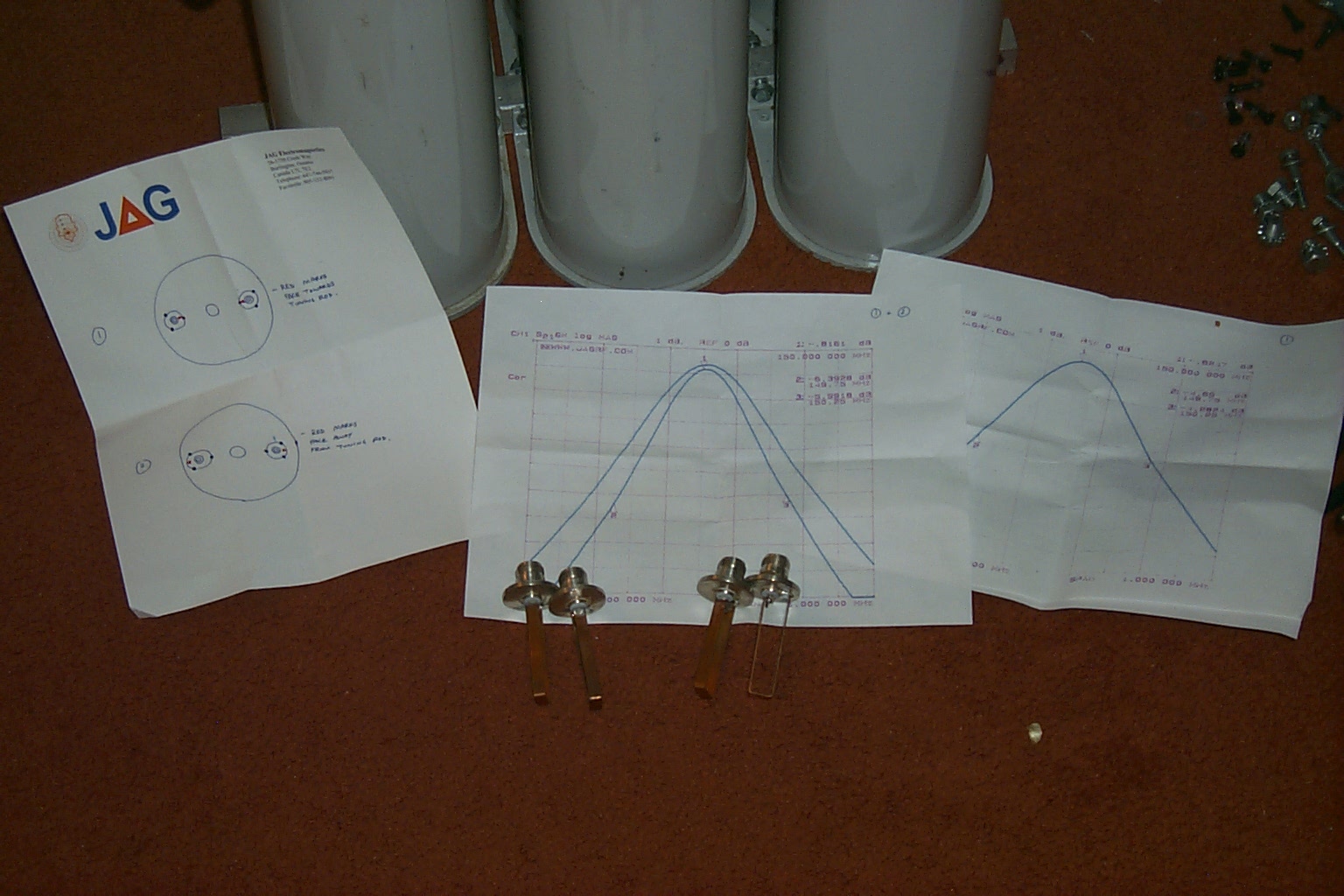
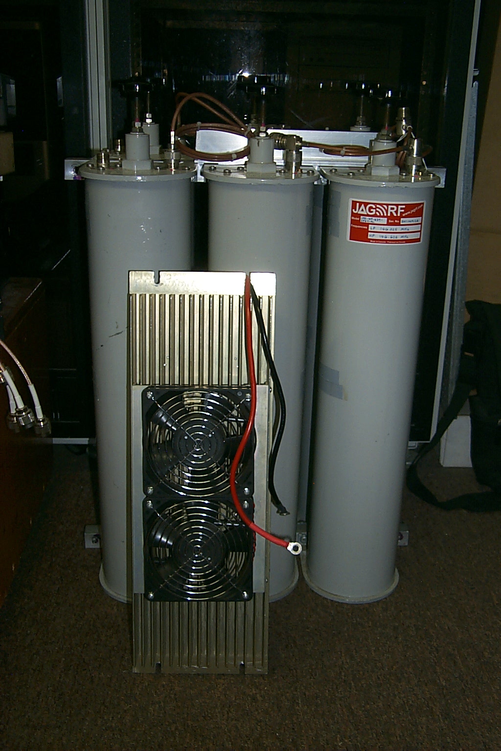
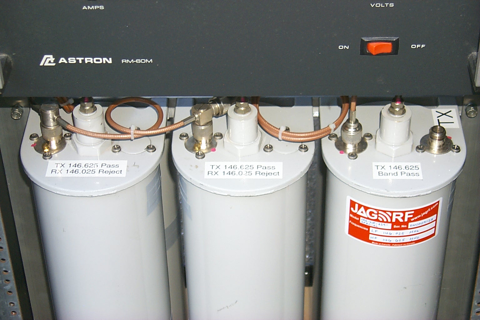
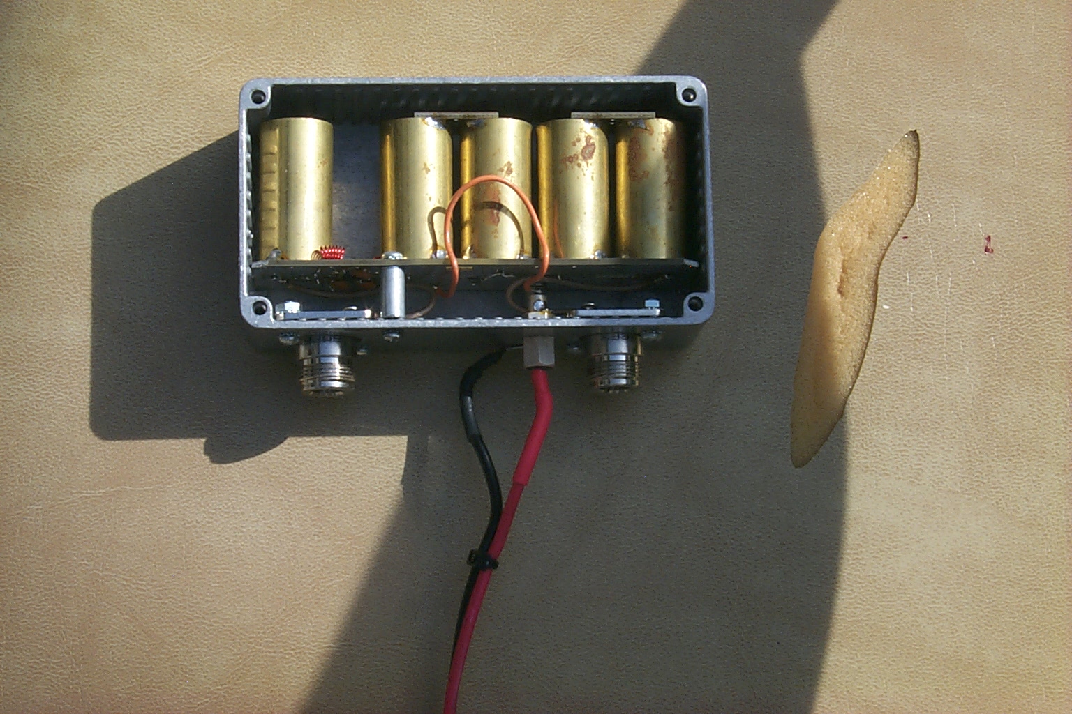
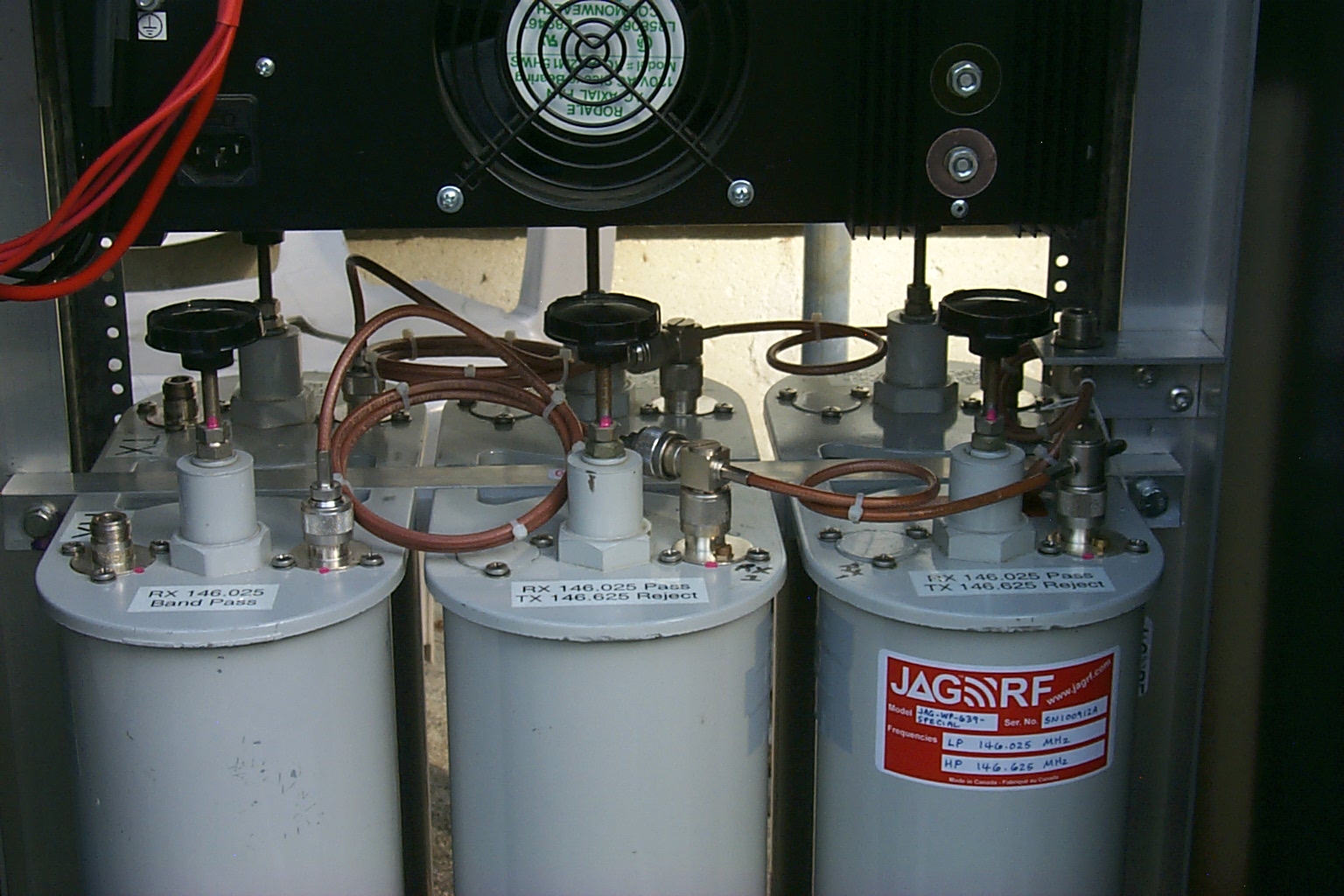
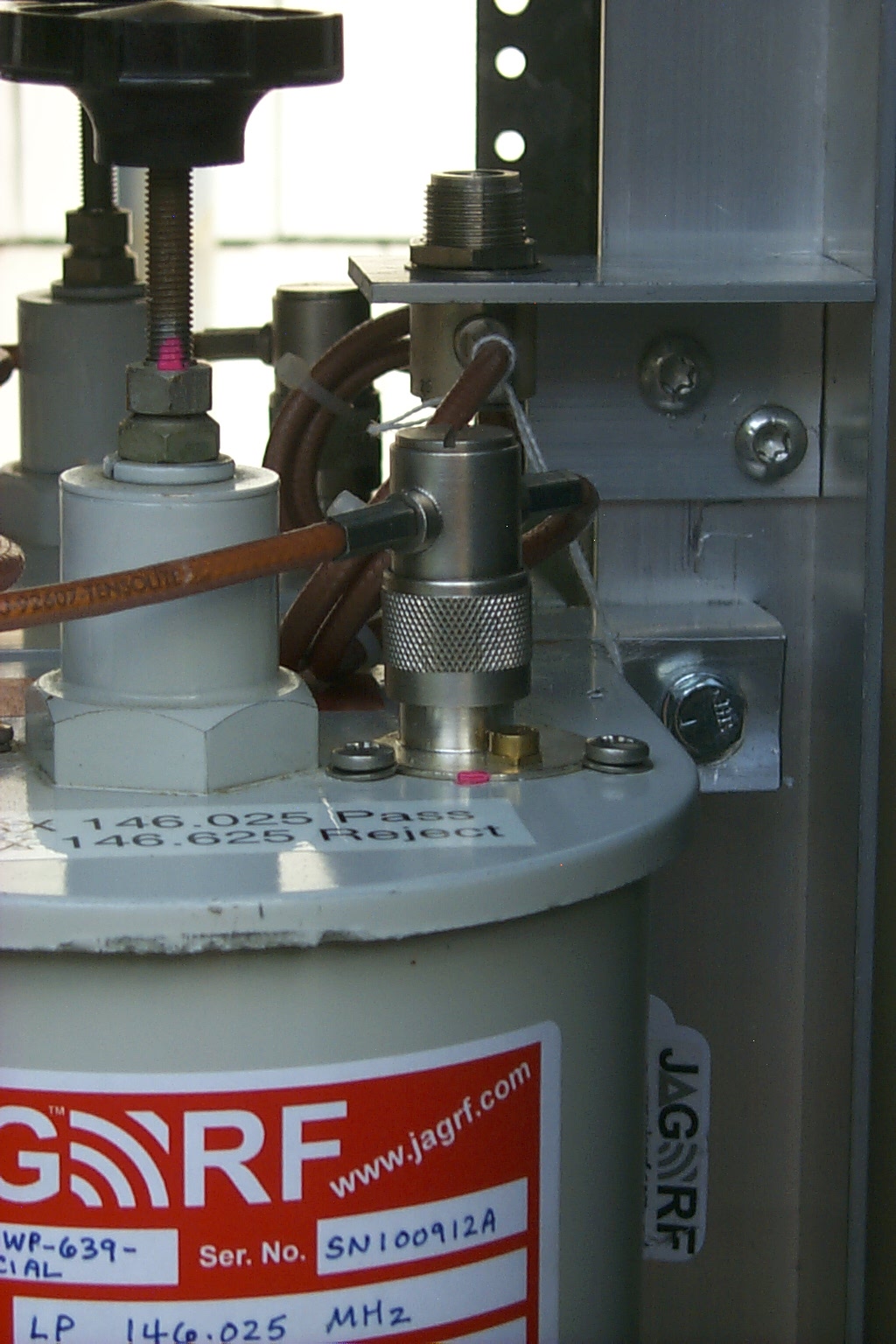
I had also added two additional bandpass cavities to the four cavity BpBr duplexer converting all of the cavities from SO-239 couplers to Type-N couplers. My friend Jag from JAG Electromagnetics helped out with some custom coupling loops and a custom phasing harness.

(click on images to enlarge)
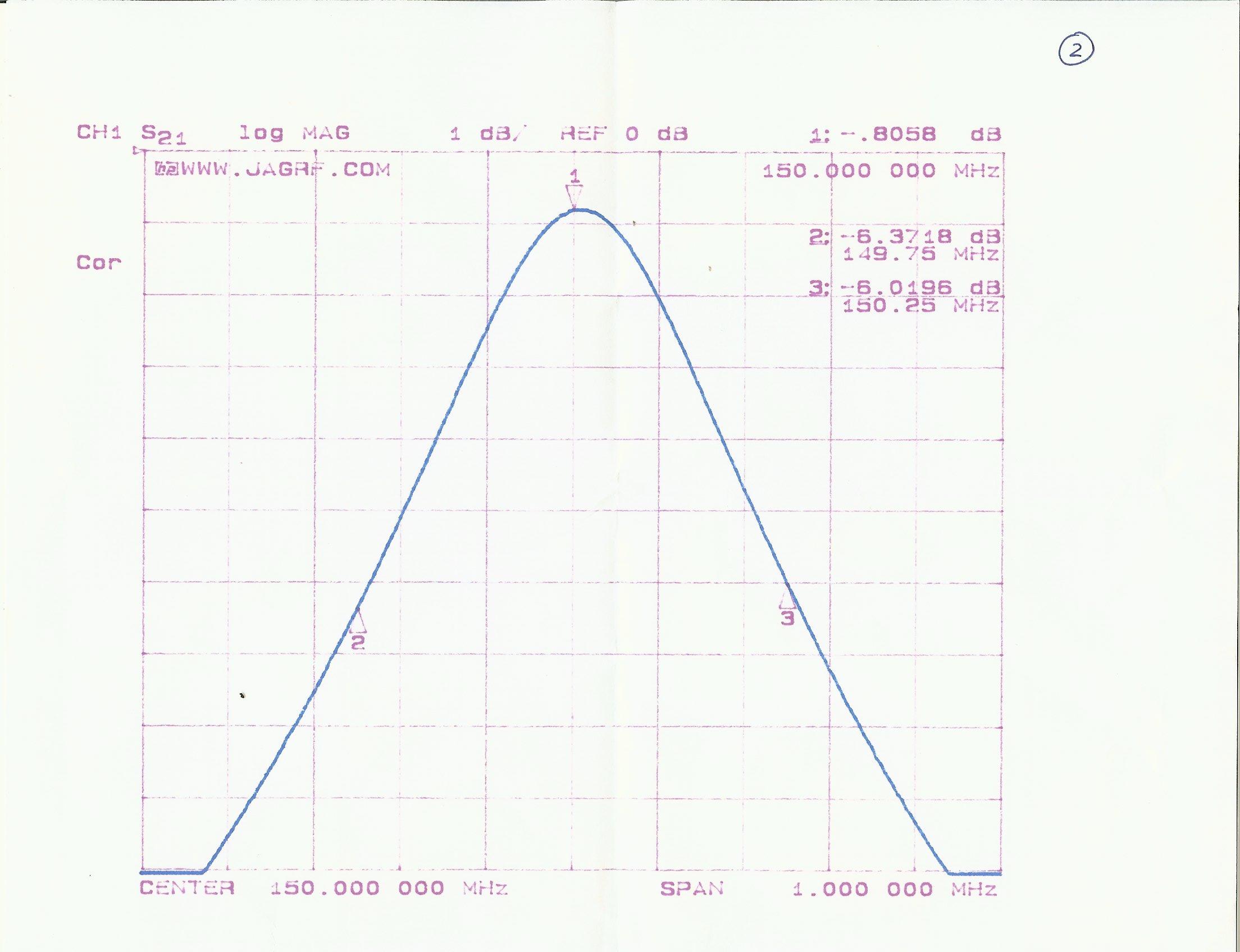
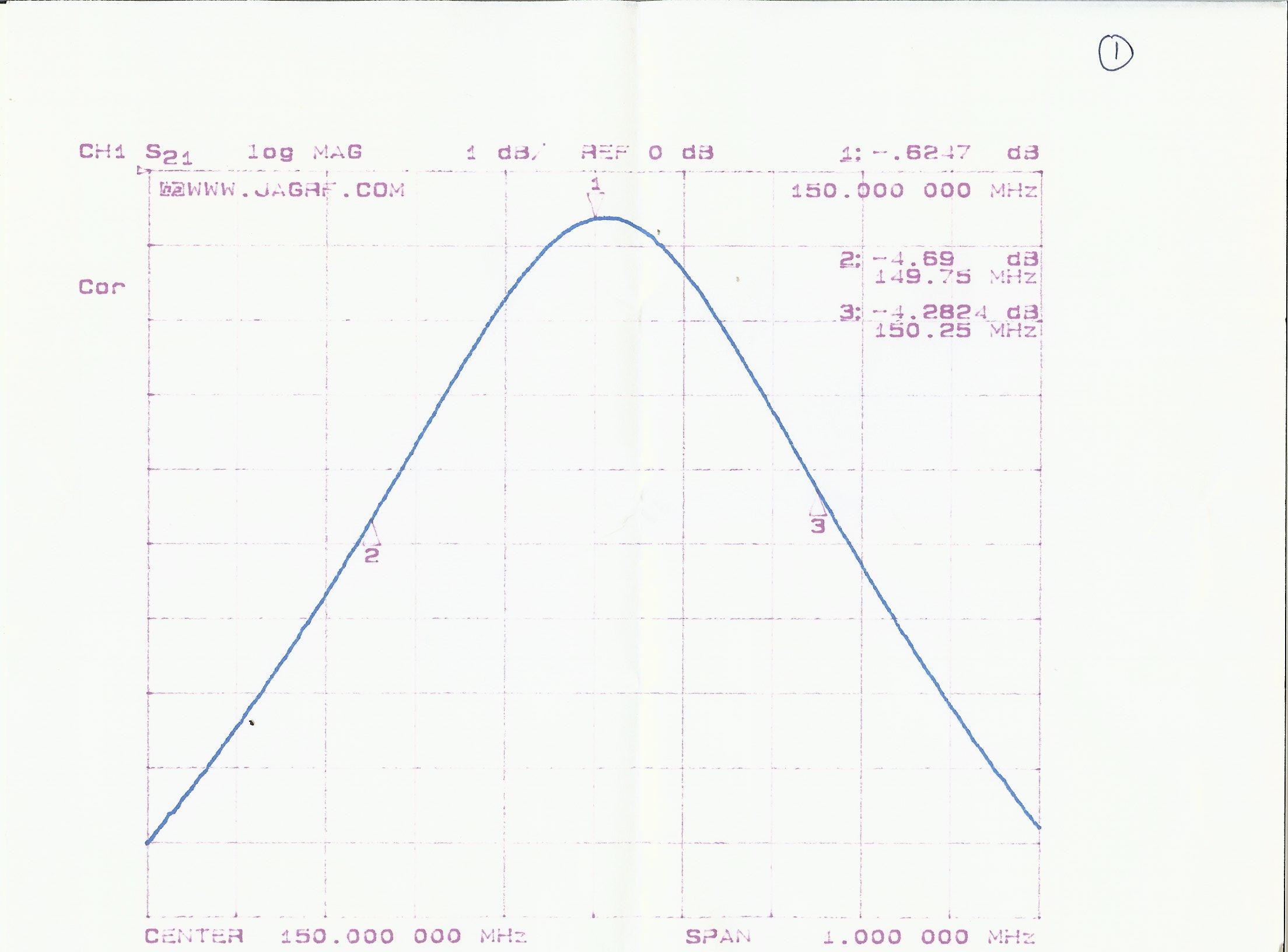
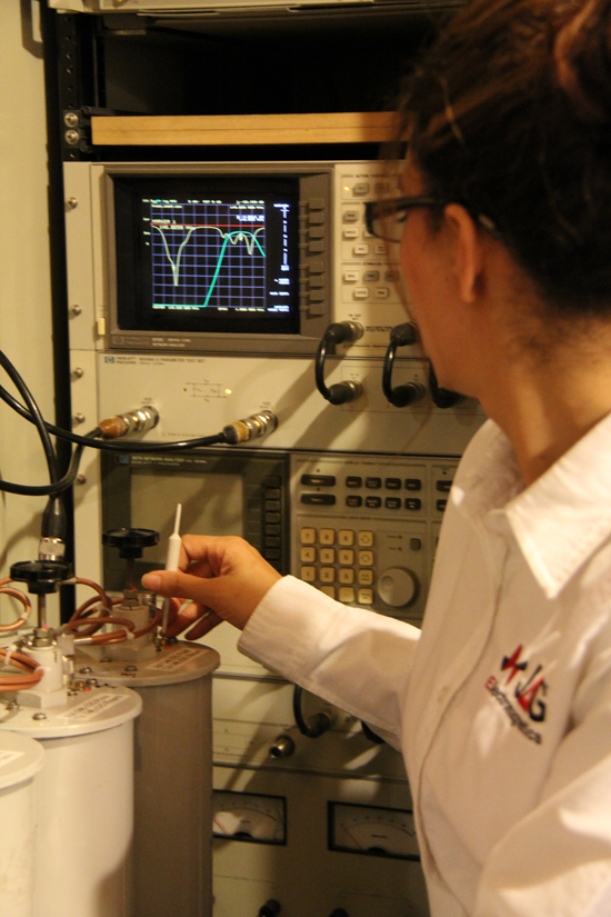
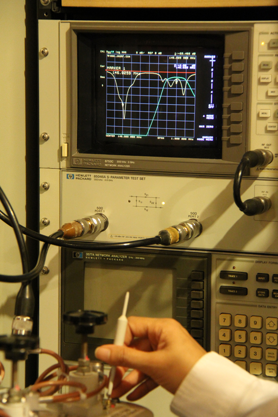
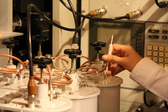
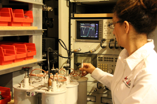
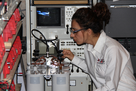
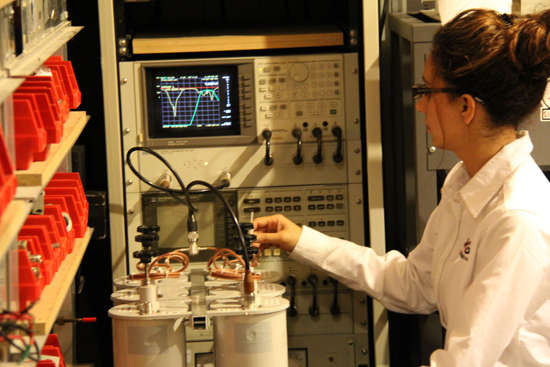
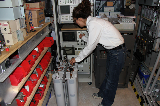
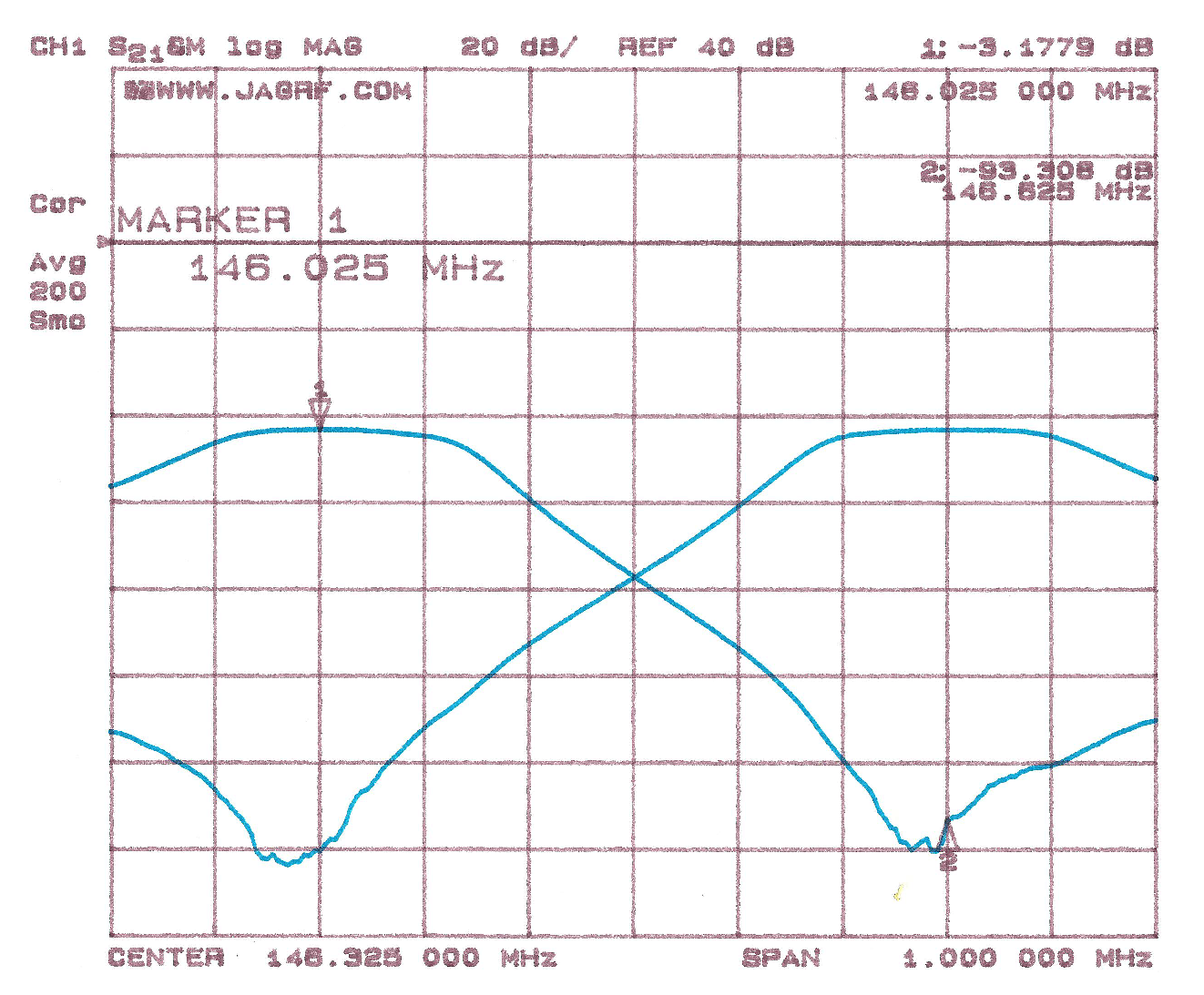
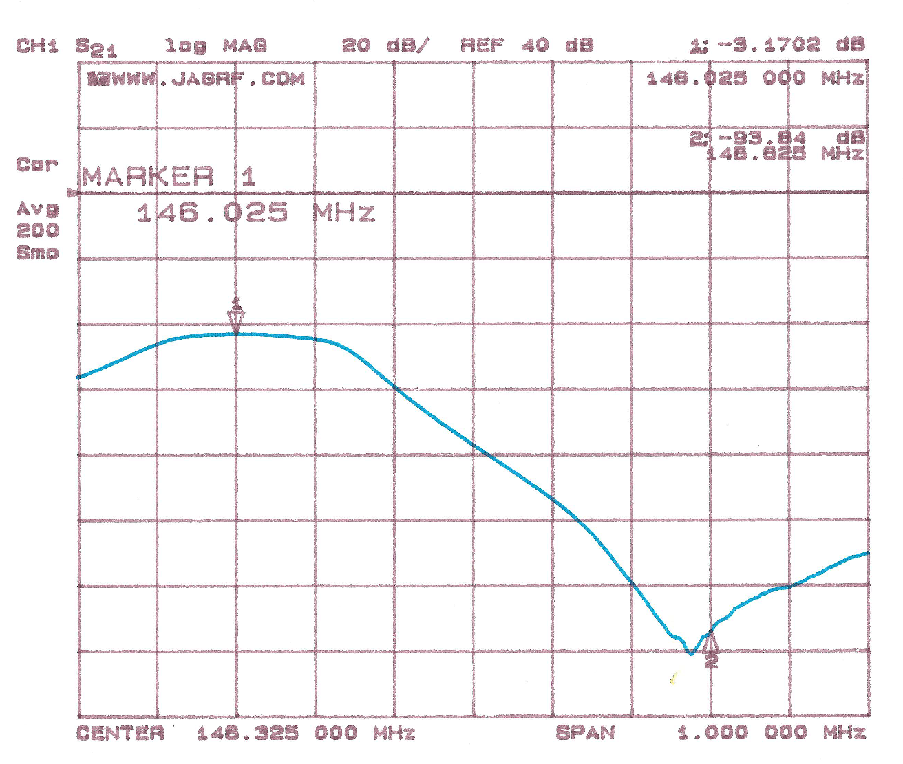
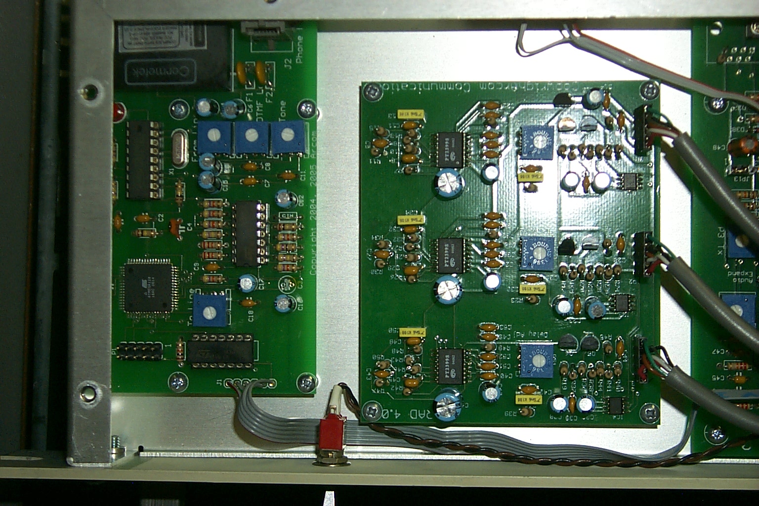
Tuning the Cavities...
Jag and his wife Amandeep did an awesome job tuning up the cavities in their lab with the custom loops and phasing harness. The rebuilt six cavity duplexer tuned up very well, with approximately 3 dB of insertion loss and close to 100 dB of isolation.
![]()
(click on images to enlarge)
The Boy gets sick...
Not long after the project to build a new repeater got started I was diagnosed with advanced stage four male breast cancer and went into the hospital for extensive treatment. All of my repeater projects were put on
indefinite hold while we focused all efforts on my illness. Sixteen months later, with 12 surgeries, 38 radiation treatments, 52 chemotherapy
treatments, countless doctor visits, and $770,000.00 in medical bills behind me I got back to work.
During my treatment
(click on images to enlarge)
The parts are all gathered, lets get this party started...
After the last chemotherapy session in mid April 2014 the doctors told me that I would be in a 90 day period of "Rest & Recovery" so my body could heal from the 15 months of hell they had just put me through. In my mind that translated into time to go back to work on all the repeater projects...
...With all the hardware collected and tuned up for the 146.625 / 146.025 frequency pair it was time to build the box that would go BEEP!
(click on images to enlarge)
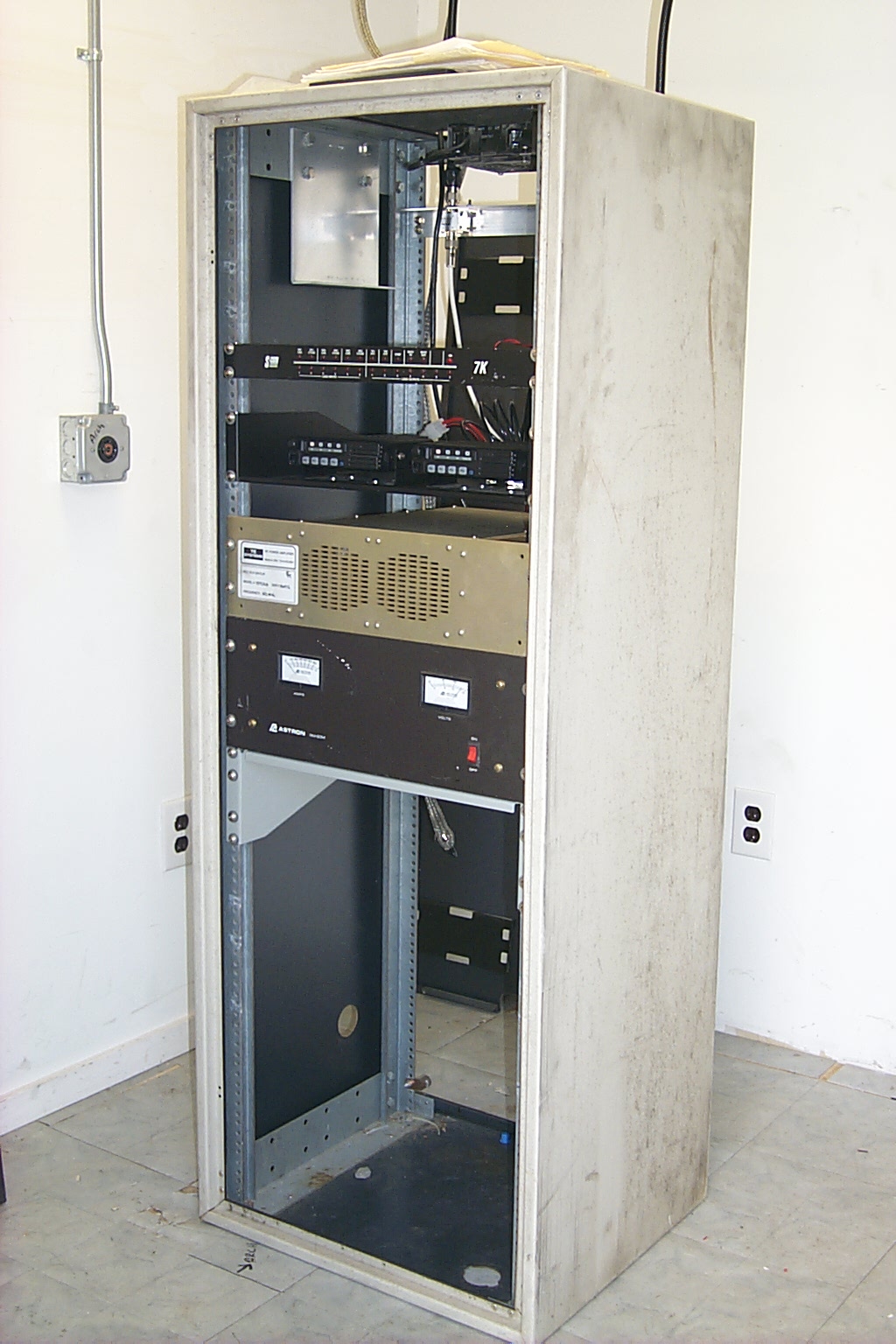
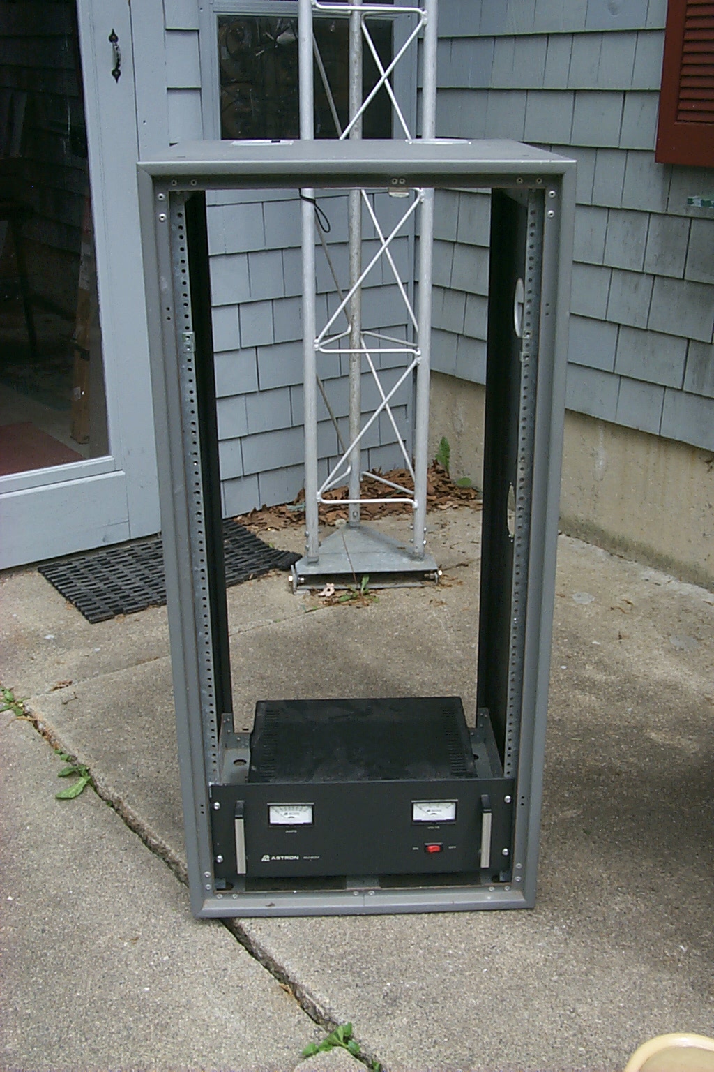
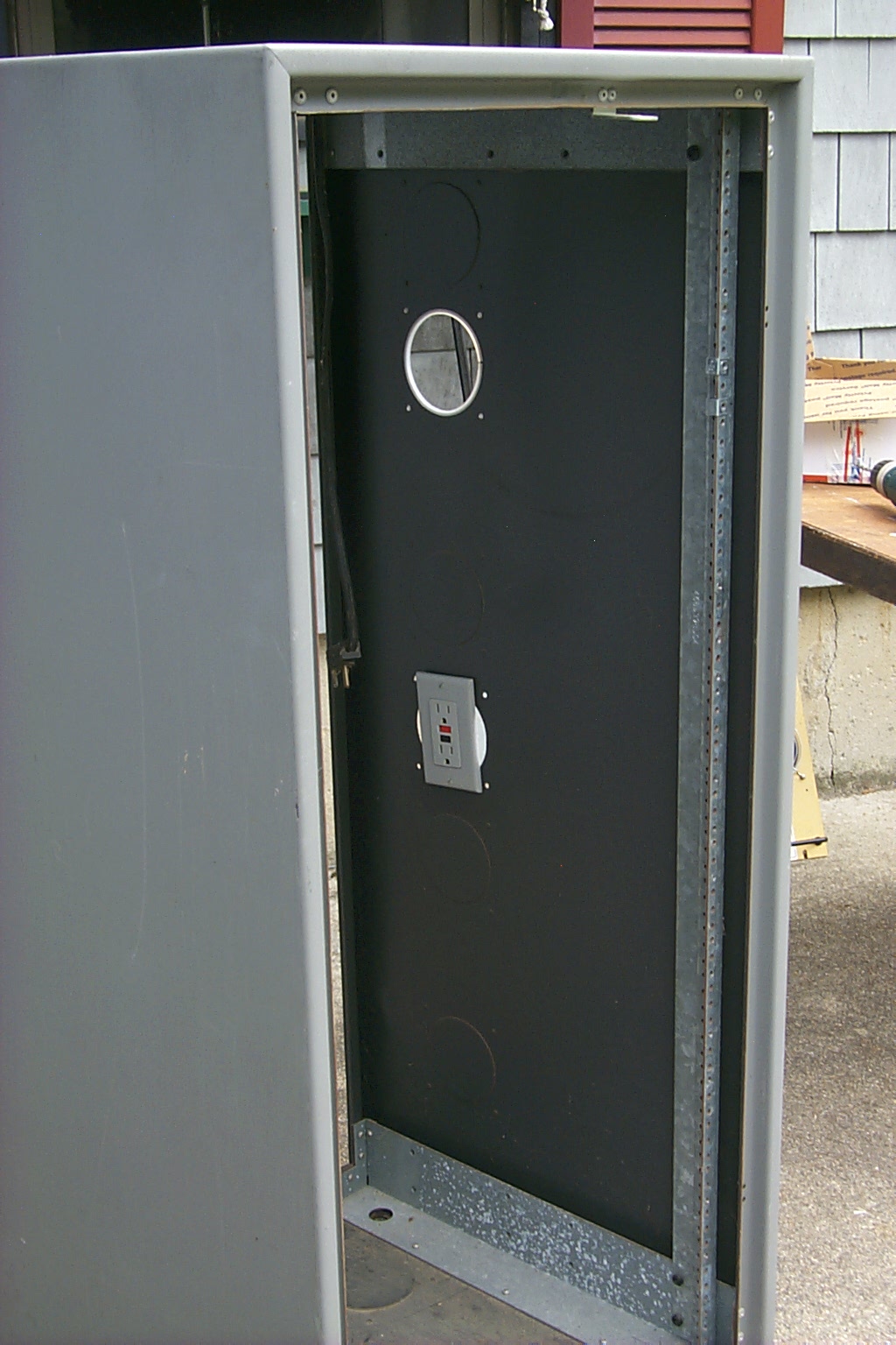
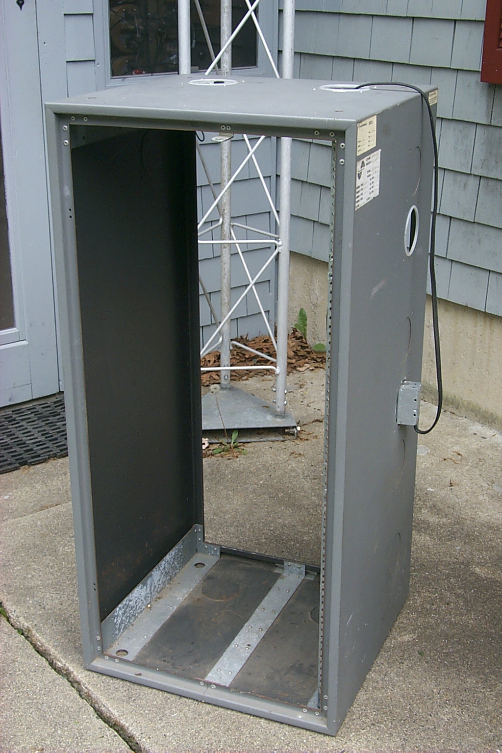
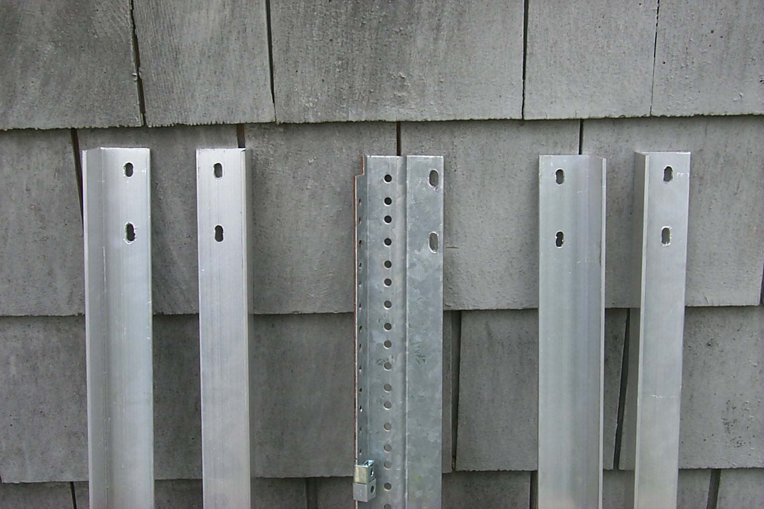
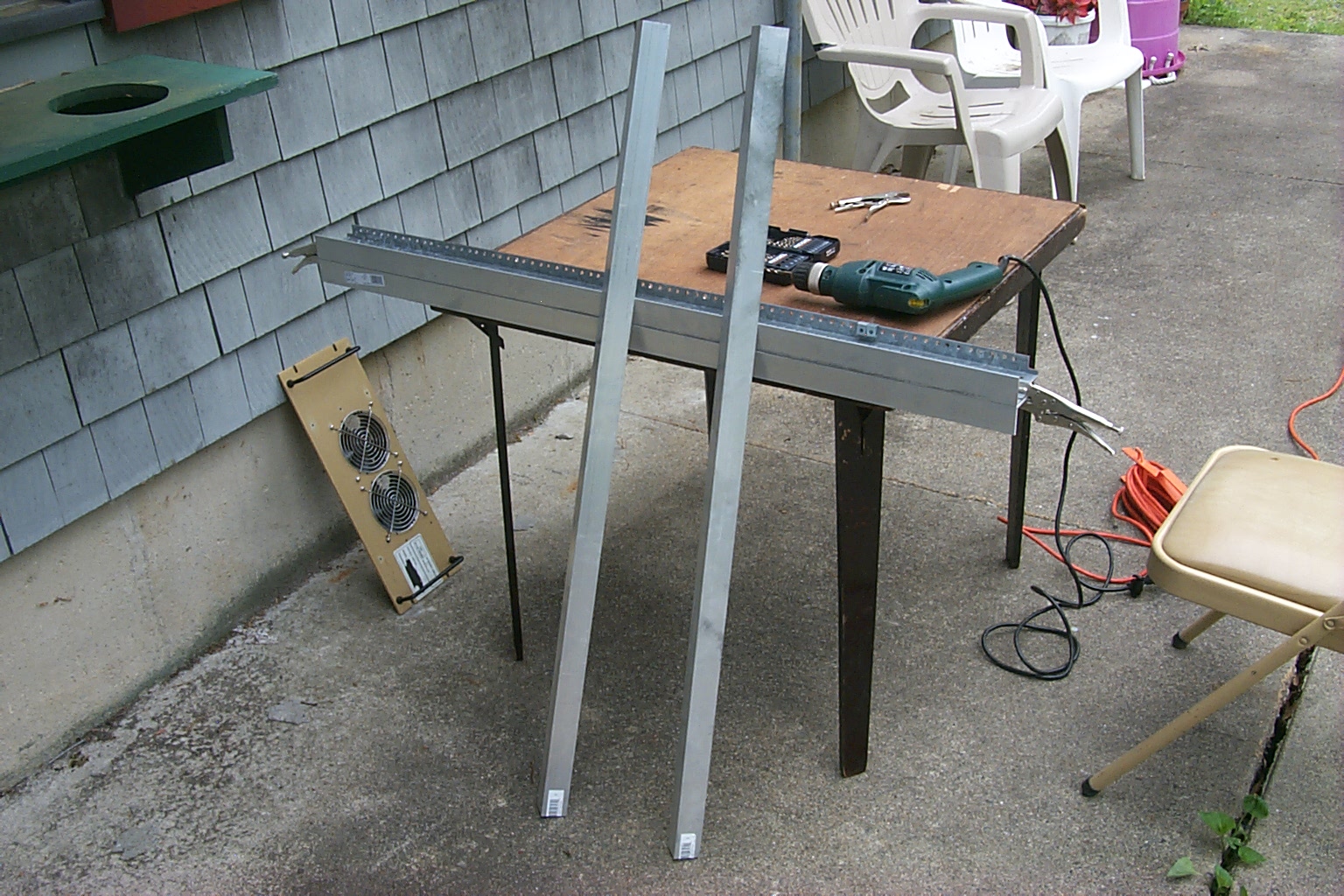
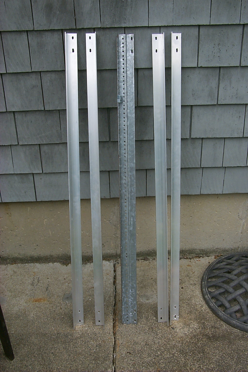
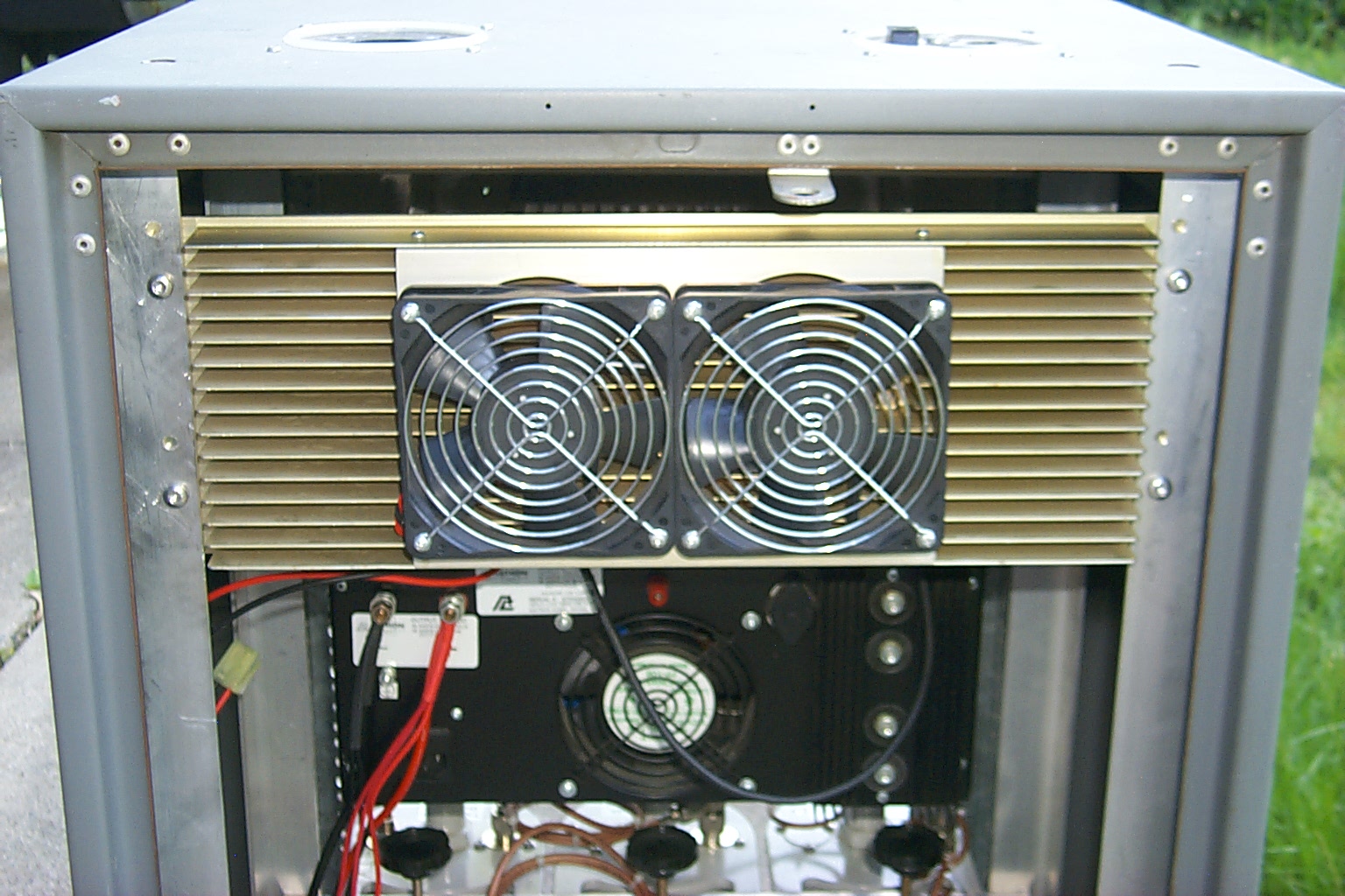
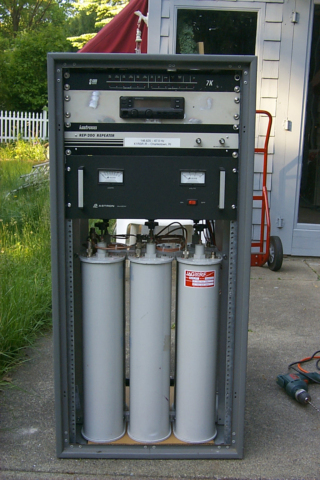
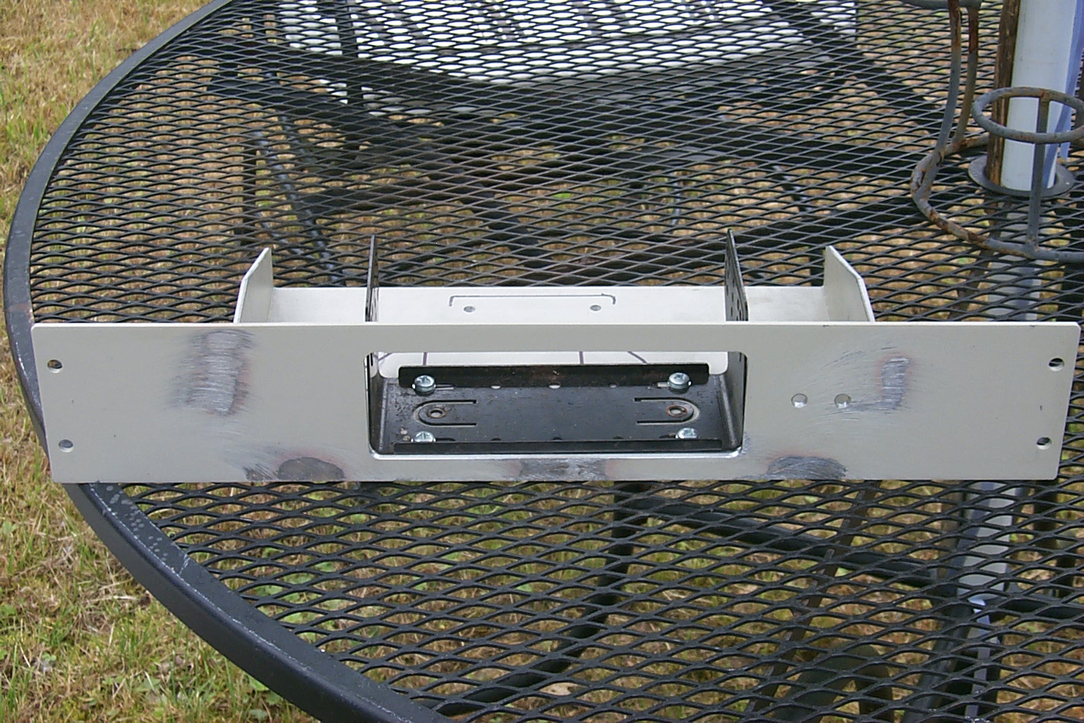
Preparing the rack cabinet...
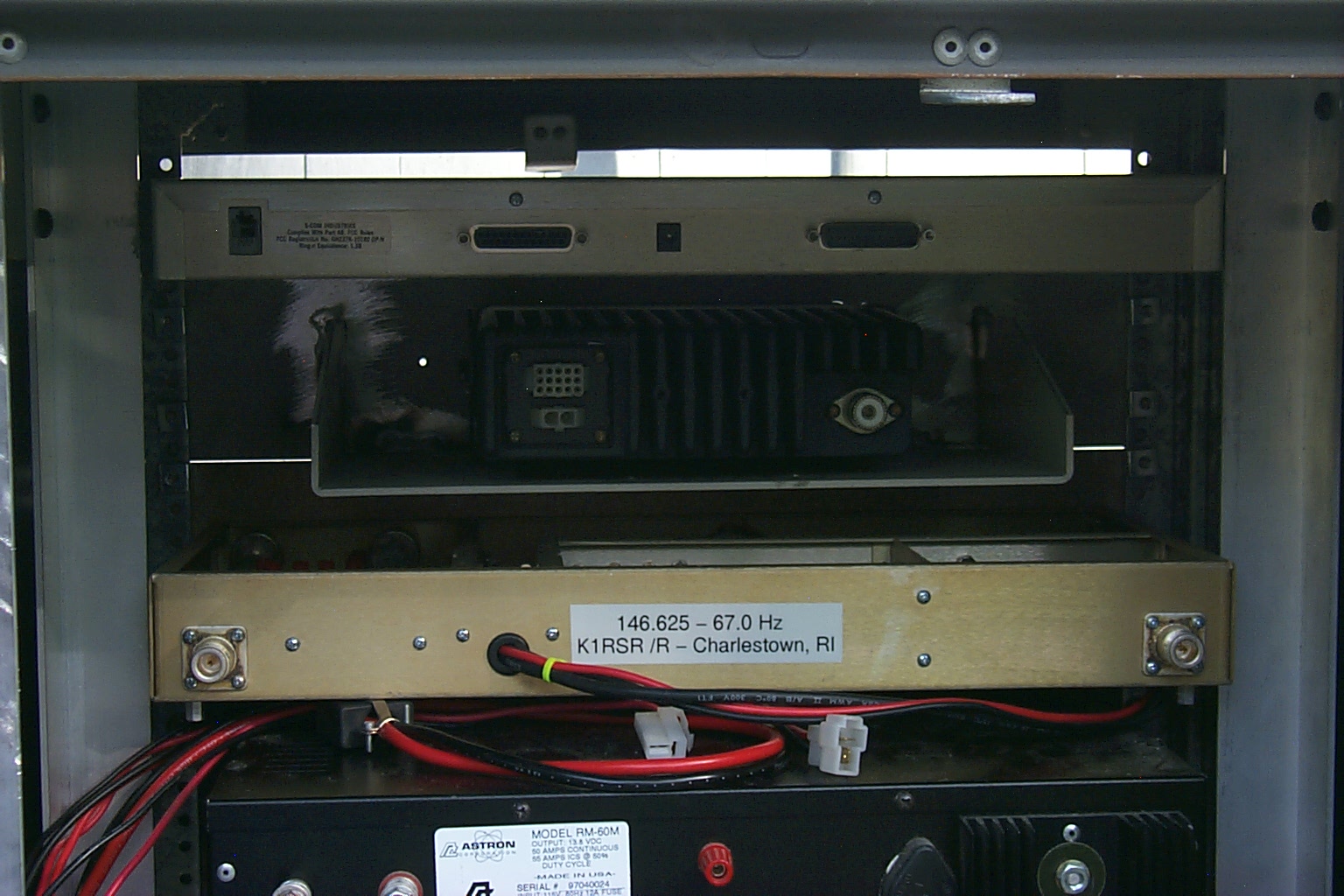
The Motorola cabinet only had one set of mounting rails along the front so I had to make custom rails to mount the duplexer in the middle of the rack, and custom rails to mount the power amplifier and receive preselector / preamp in the back of the rack.
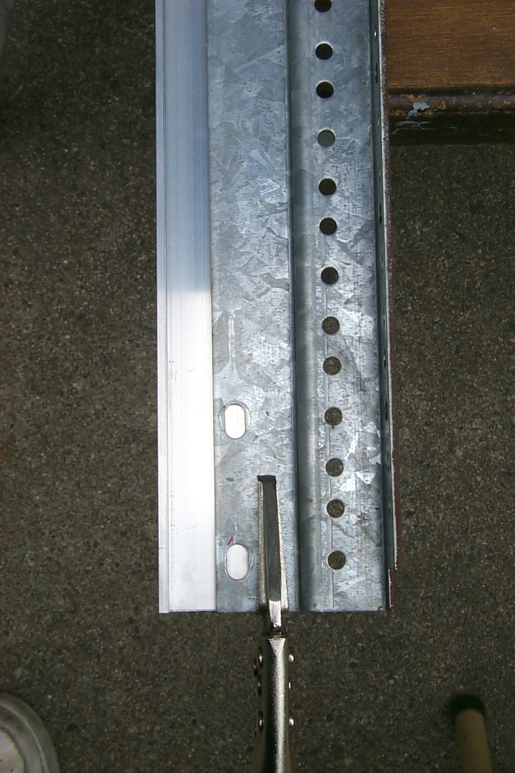
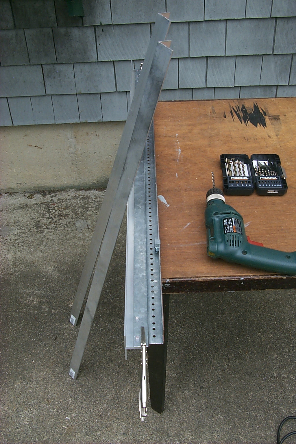
(click on images to enlarge)
More custom radio rack mounts.
My brother-in-law made me some more custom rack mounts for the Kenwood TK-30 series radios that I use for link radios and all of the hardware fit very nicely in the rack cabinet.
(click on images to enlarge)
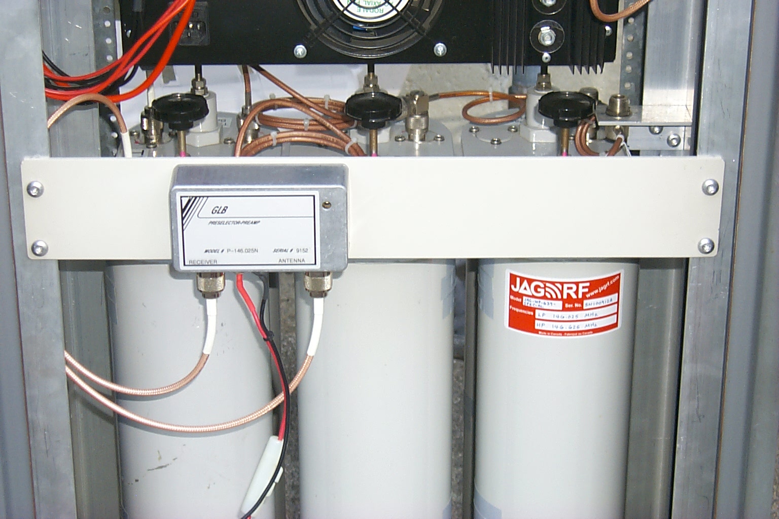
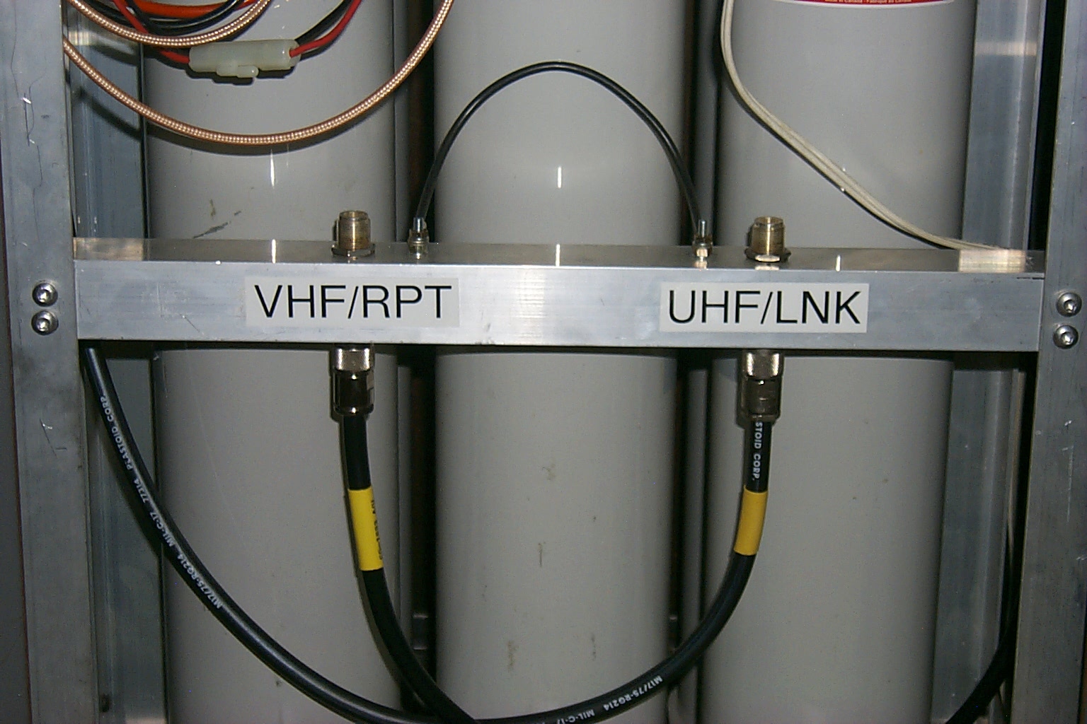
Next I made a custom mount for the GLB Preselector / Preamp and a custom bracket to support the antenna TEE connector on the duplexer phasing harness.
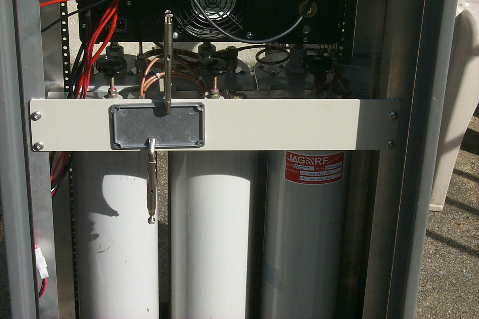
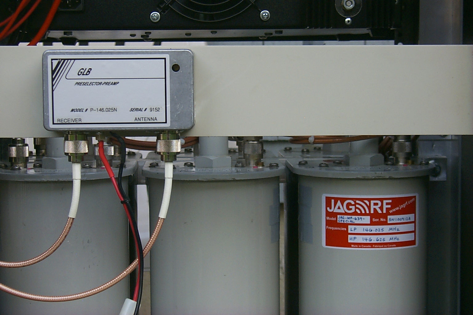
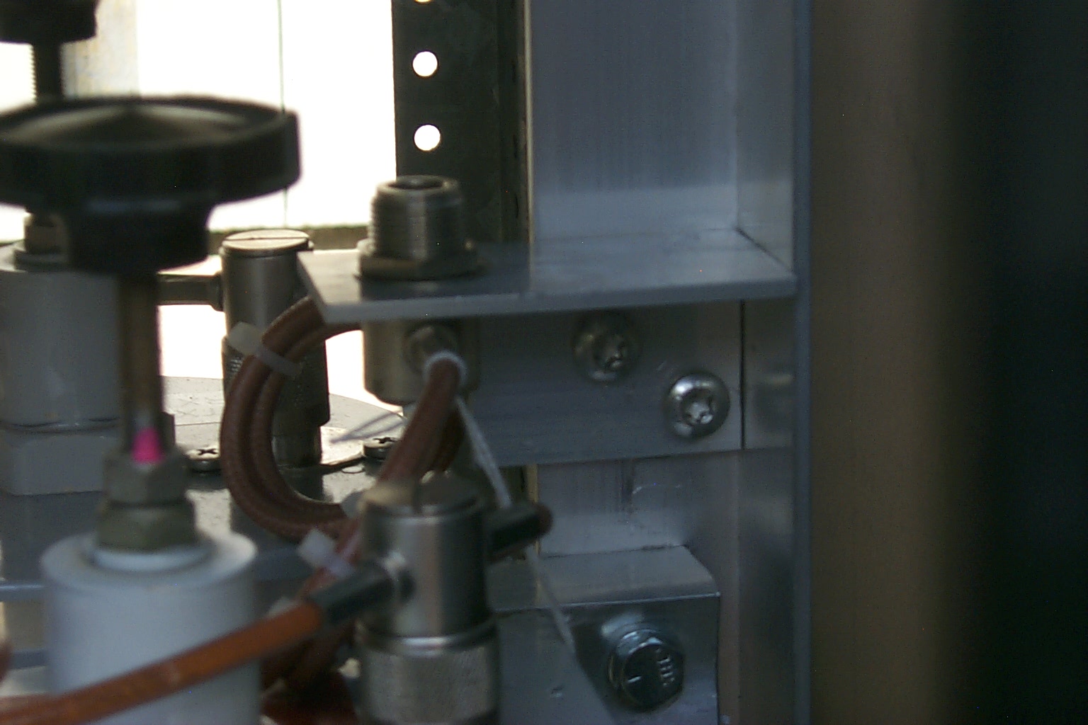
(click on images to enlarge)
With all the components mounted in the rack cabinet it was really starting to look like a big box that goes BEEP! I made some 1/2 wave jumpers to interconnect the RF using MilSpec RG-142/U double shielded coax which matched the custom phasing harness that Jag made. All that was left was to made the COS, CTCSS, and Audio modification to the Kenwood TK-830 UHF link radio and make the S-Com 7k controller cables.

(click on images to enlarge)
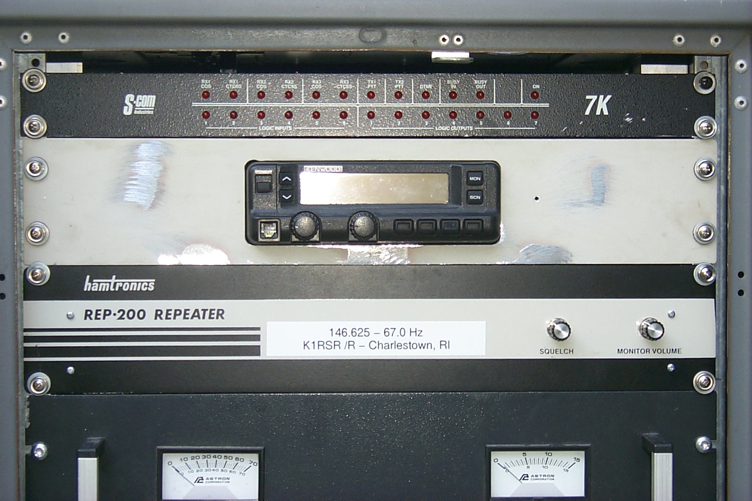
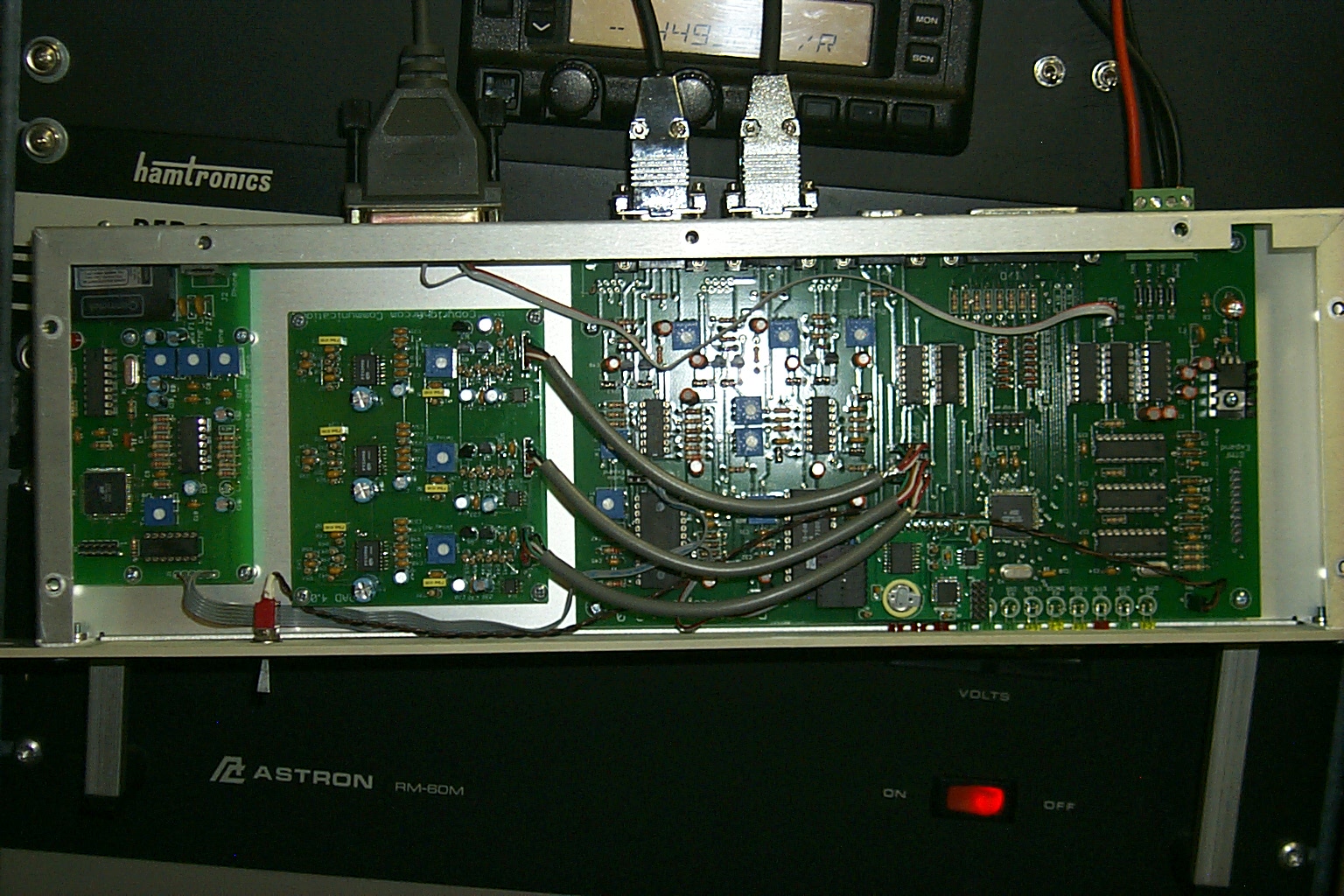
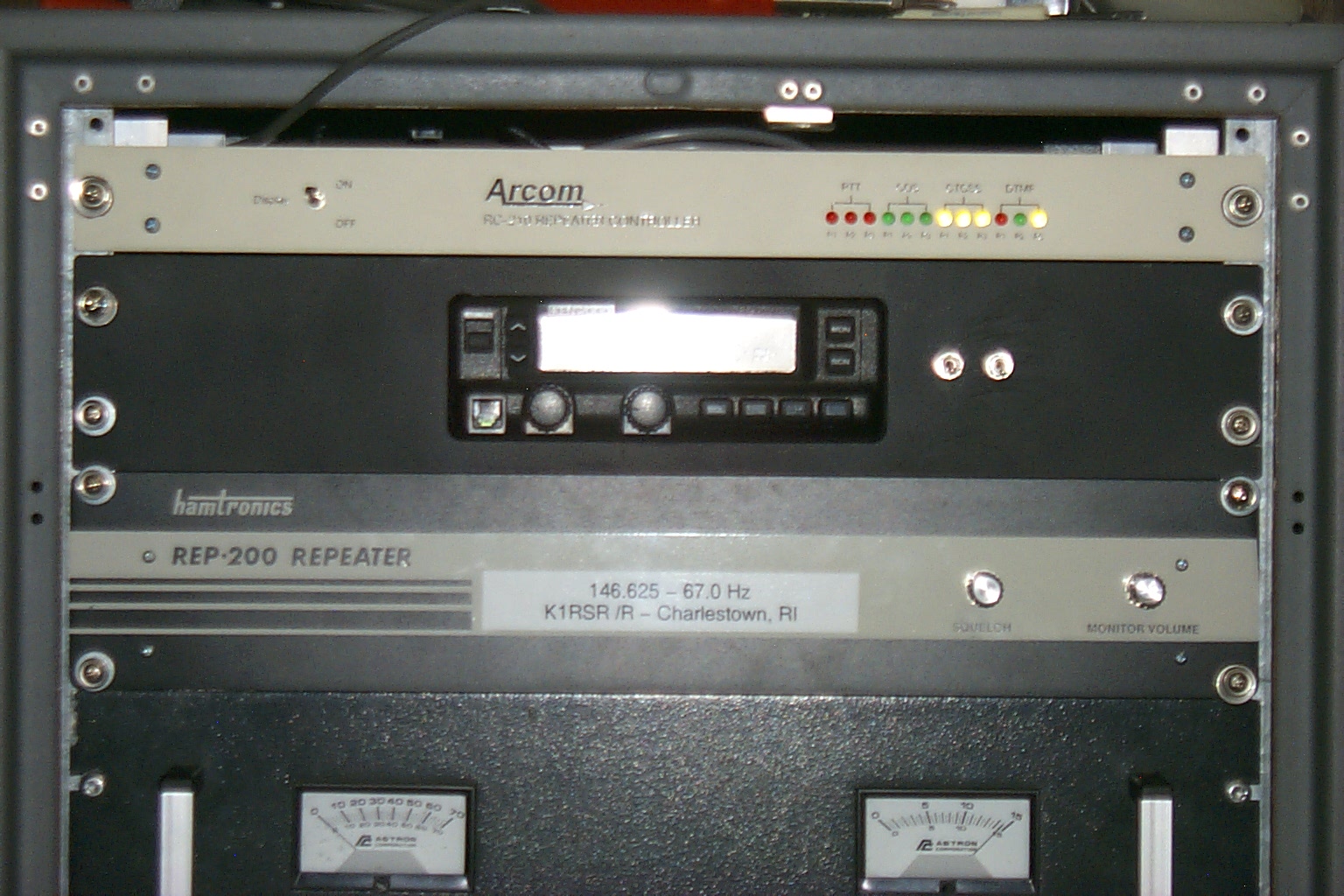
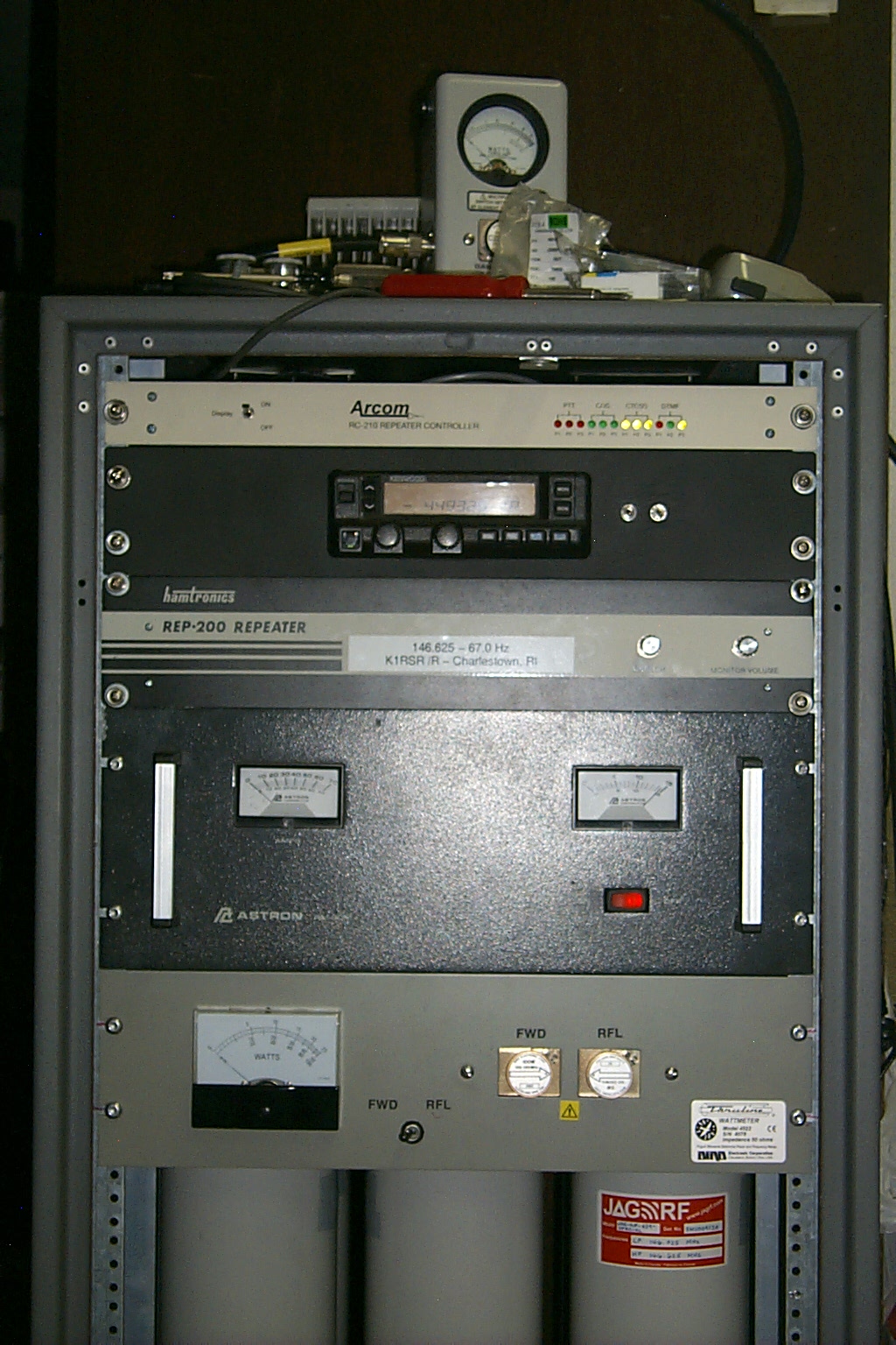
The big box goes BEEP!
With all the hardware fabrication completed and all the components mounted in the rack cabinet I dragged the repeater into the shack to finish up the controller cables and modify the UHF link radio. While digging in the parts pile I uncovered one of my RC-210 controllers that had been on the Johnston repeaters until I upgraded them to a new S-Com 7330 controller. This Hamtronics RF deck was already wired up for the RC-210 controller so I plugged it it and pressed the power button... BEEP!
(click on images to enlarge)
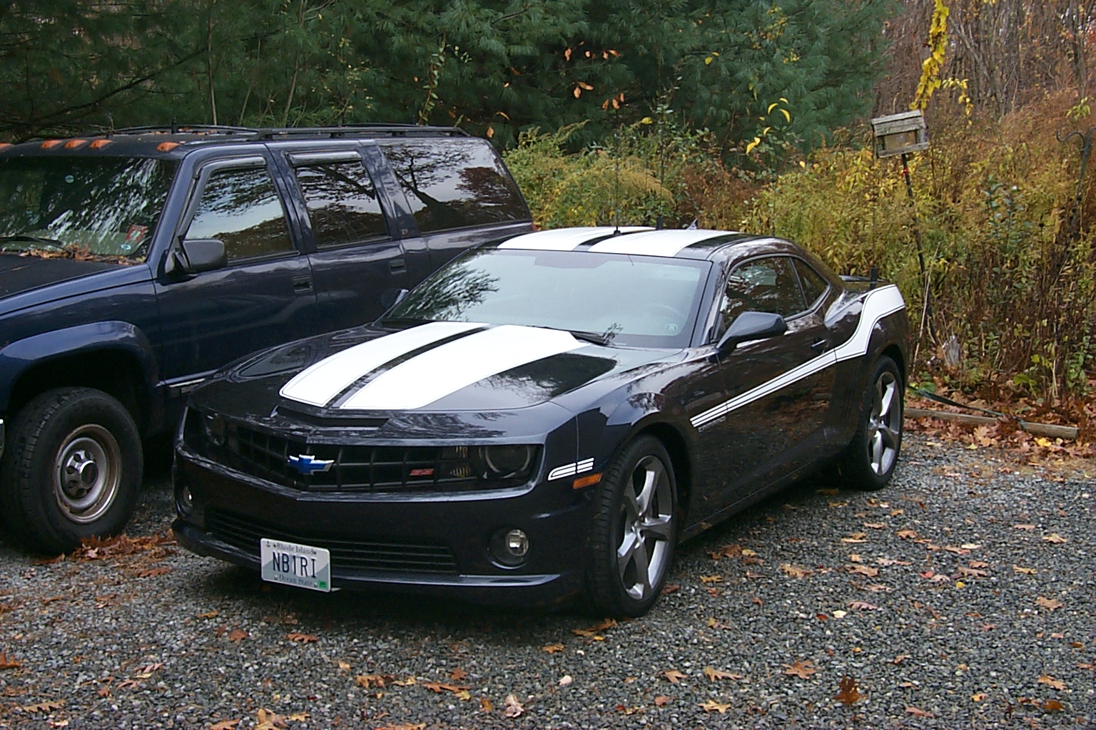
Running on a temp antenna the repeaters power output was 68 watts forward with .6 watts reflected for a VSWR of 1.21 : 1 which is very good. Sandy and I took a ride in the Shiny Blue Super Sport (NB1RI) to do some testing...
(click on images to enlarge)
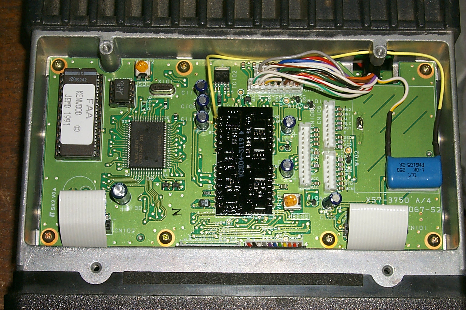
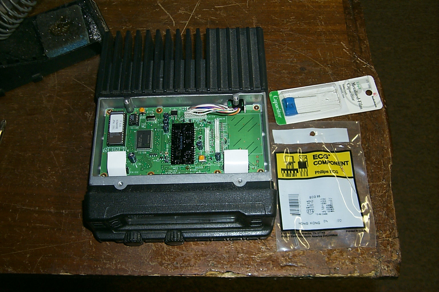
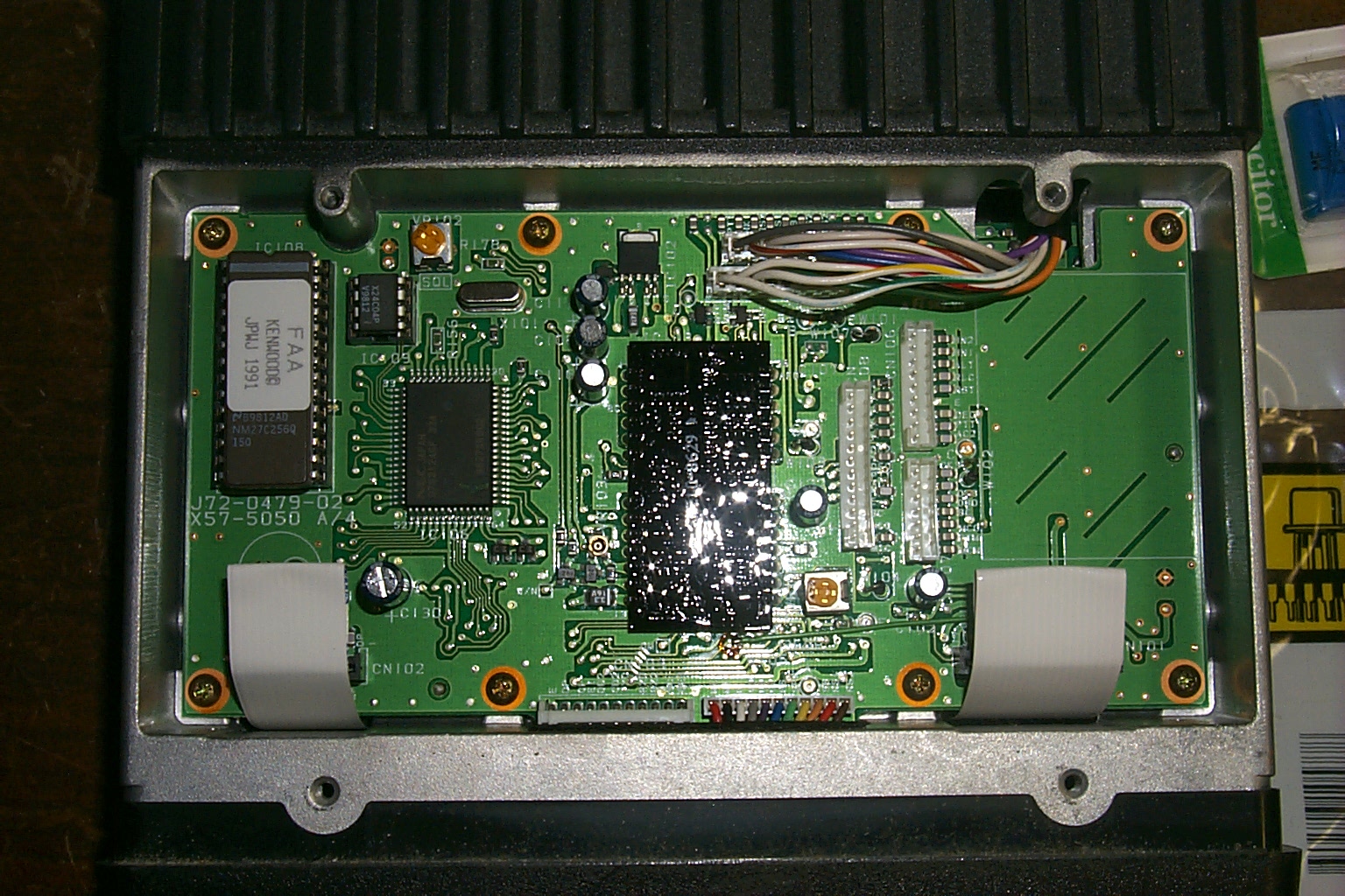
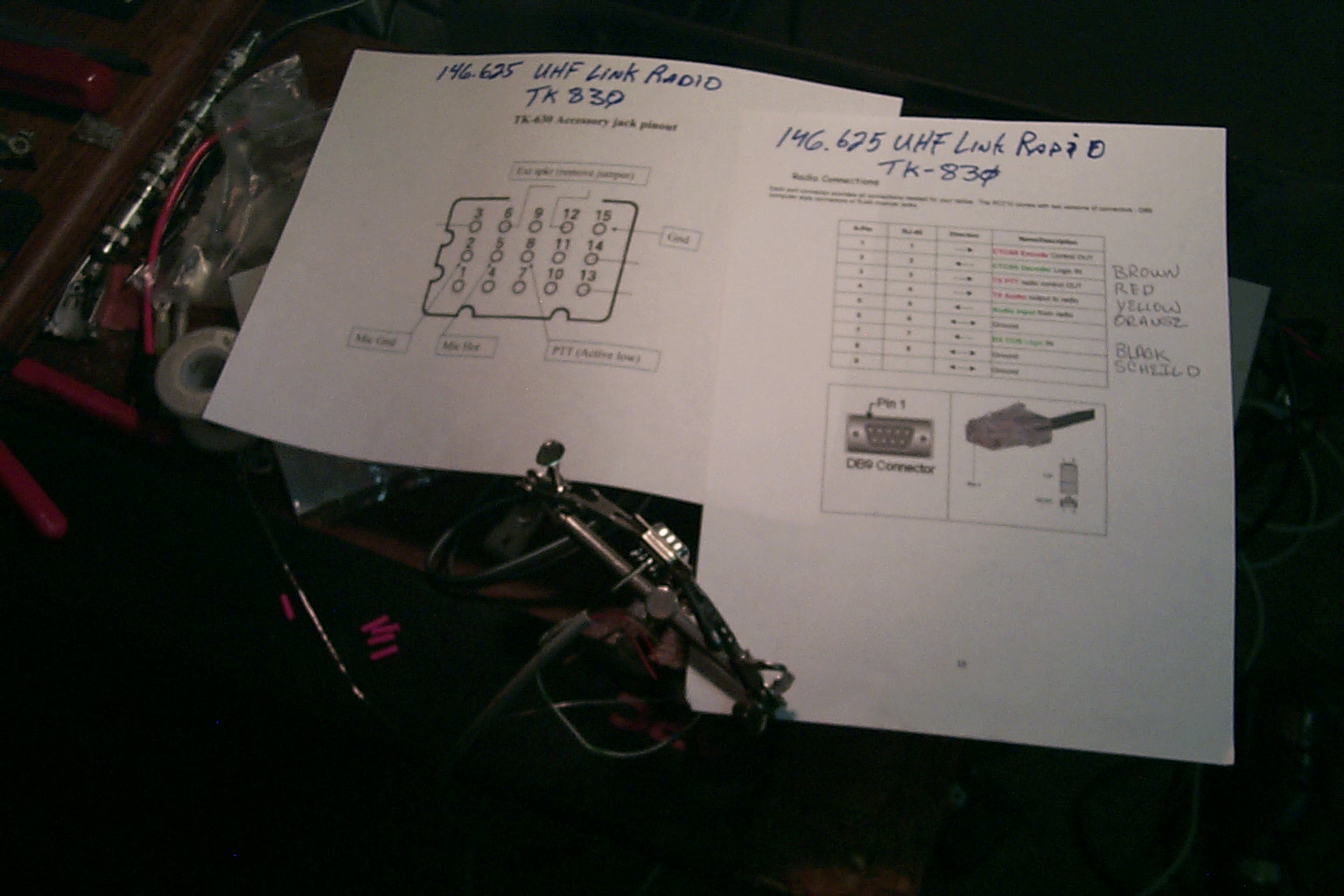
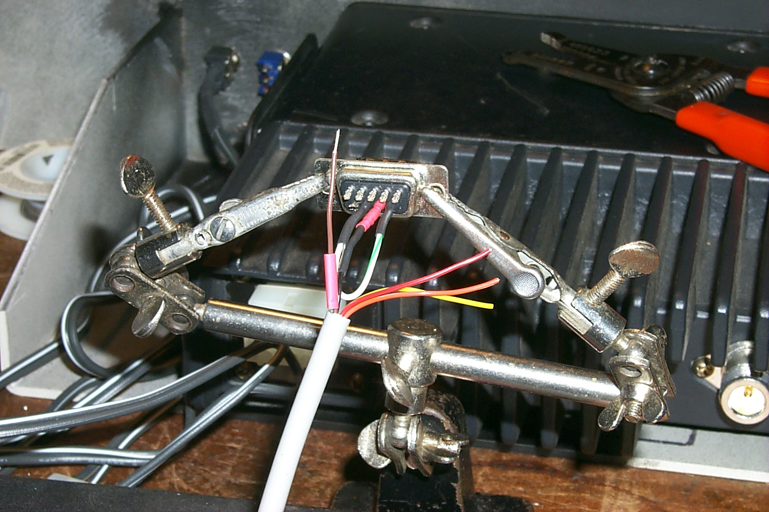
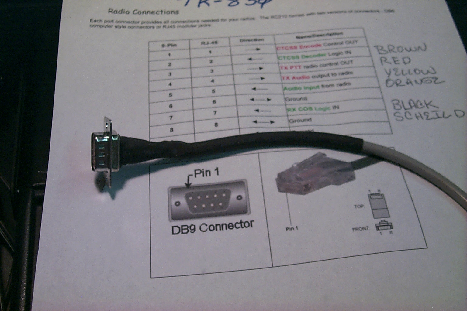
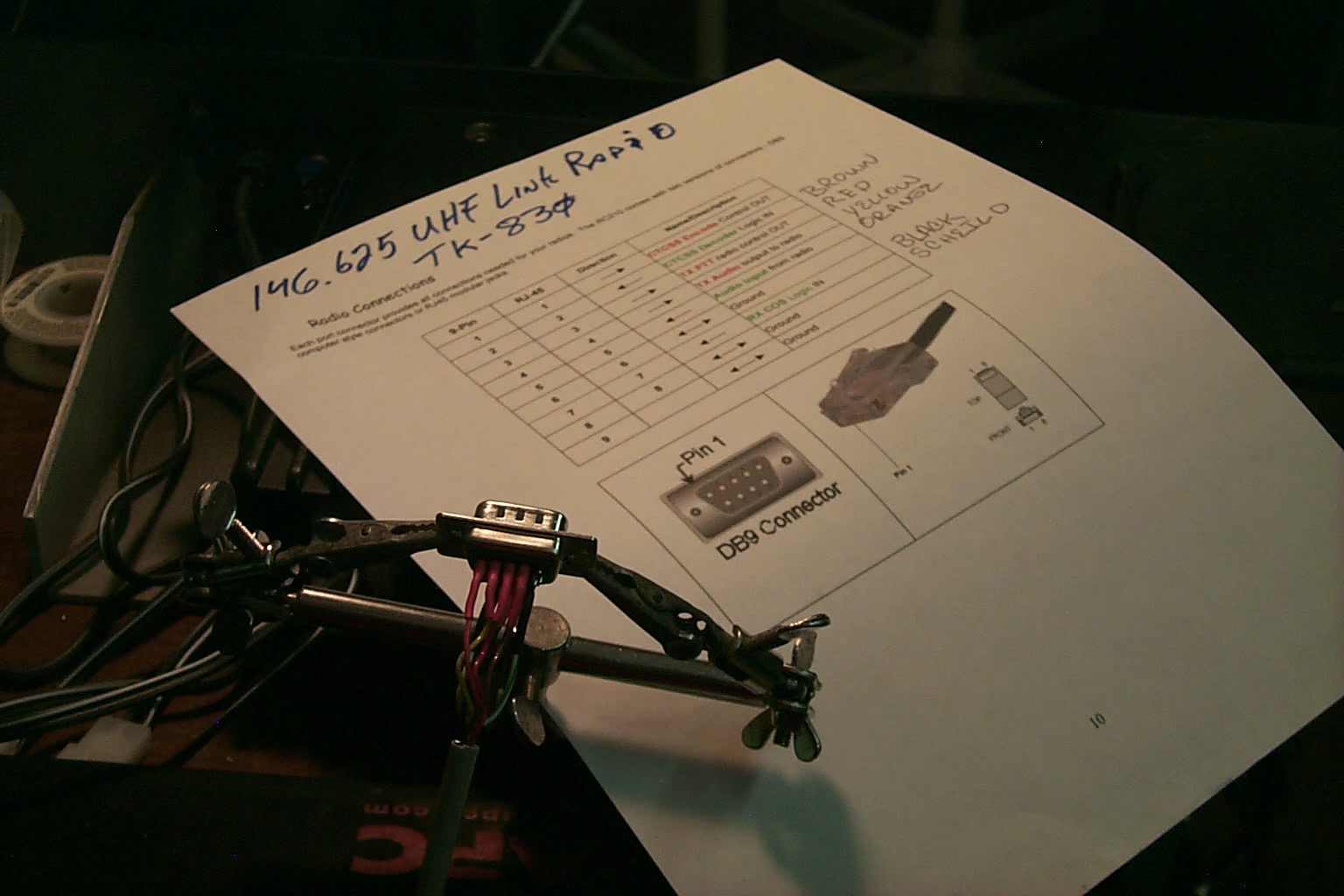
Modifying the Kenwood TK-830 UHF link radio.
I have been using the Kenwood TK-30 commercial series radios for many years now, all of my repeaters have TK-30's for either the primary transmitter and receiver, link radio, or in some cased both. Most of the radios came from eBay via government auctions or two way radio shops that had taken them in trade upgrading various police and fire departments. In this case my friend Lee N3LEE who works for a radio shop in New Hampshire donated several of these TK-30 series radios for the repeater network, one of them was a very clean TK-830 that I used for this project.
The modifications are very simple and I have done them so many times now that I can do them in my sleep.
My friend John WA1ABI took some time with an audio probe and found a good location to get the receiver audio, he also found a good location to get the CTCSS decode signal for the controller, and I was able to identify a good location to get the COS signal for the controller as well.
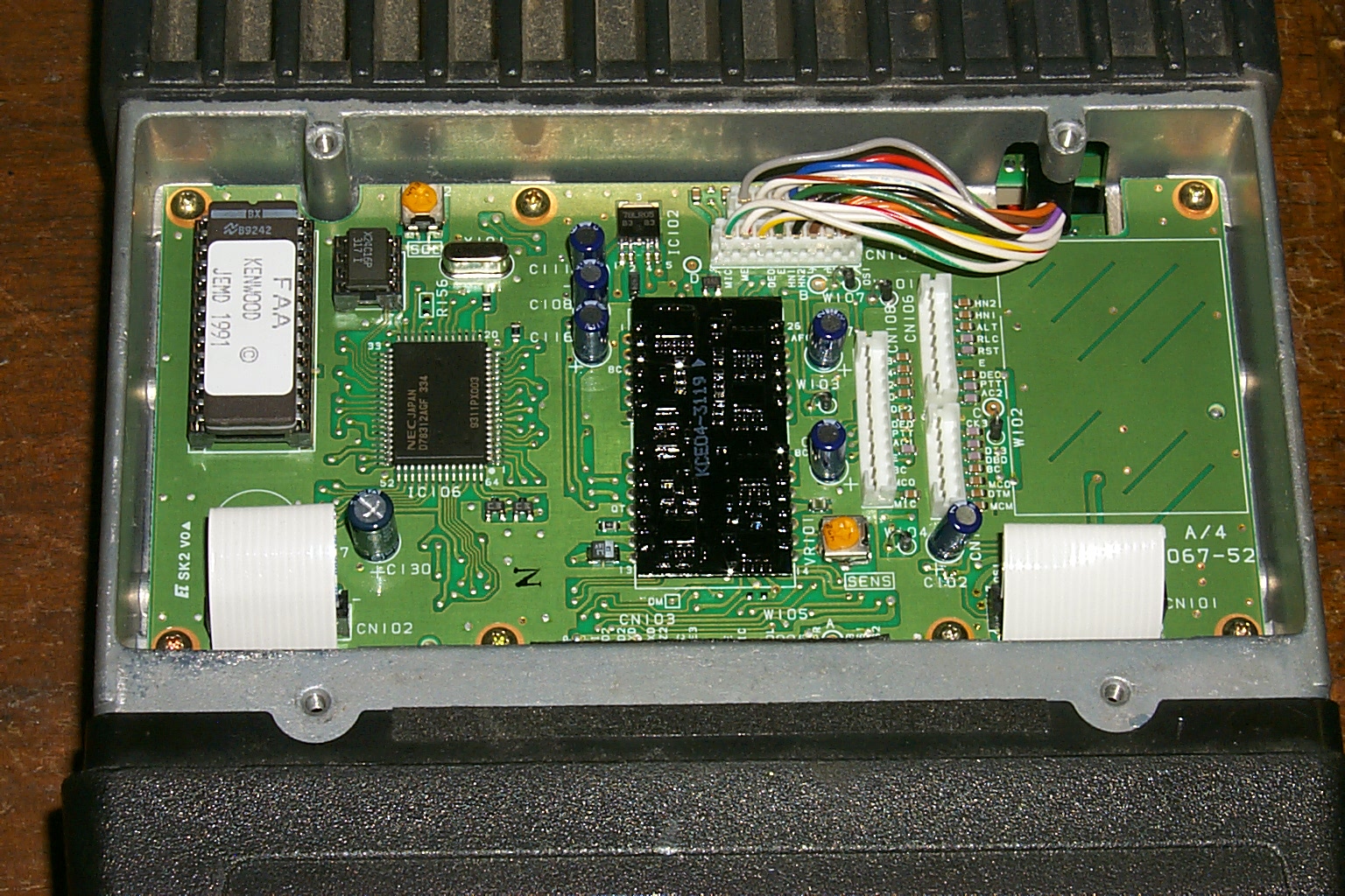
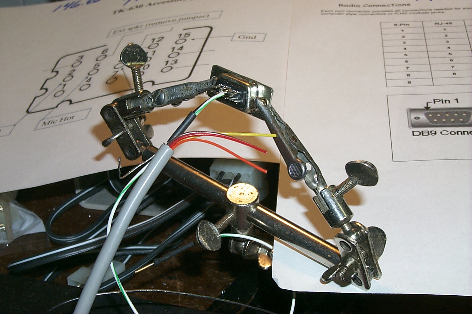
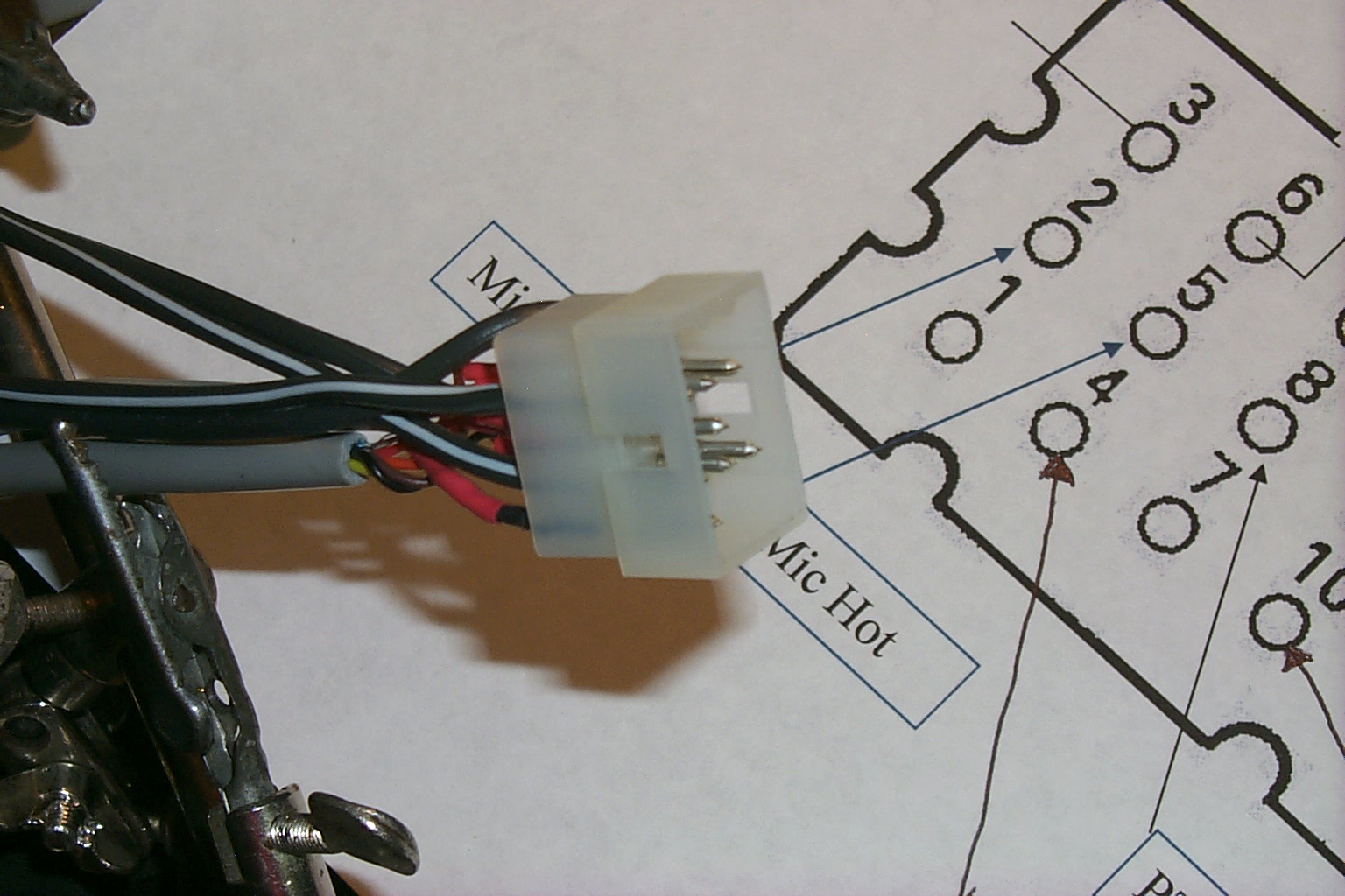
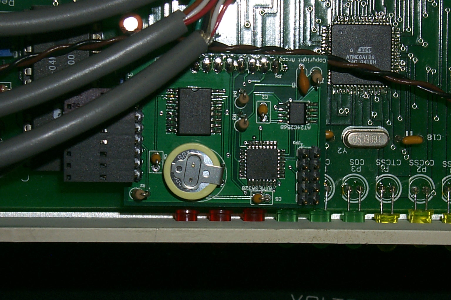
The Audio mod is really simple, just connect a wire to PIN 1 on the main IC in the center of the radio, pass it through a good quality CAP, and route it out to the back 15 pin Molex connector using the white/yellow stripe wire...
(click on images to enlarge)
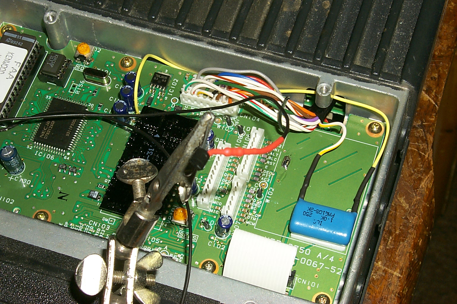
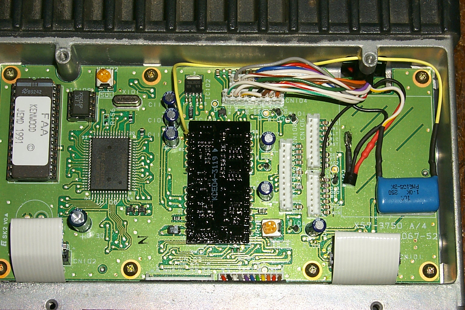
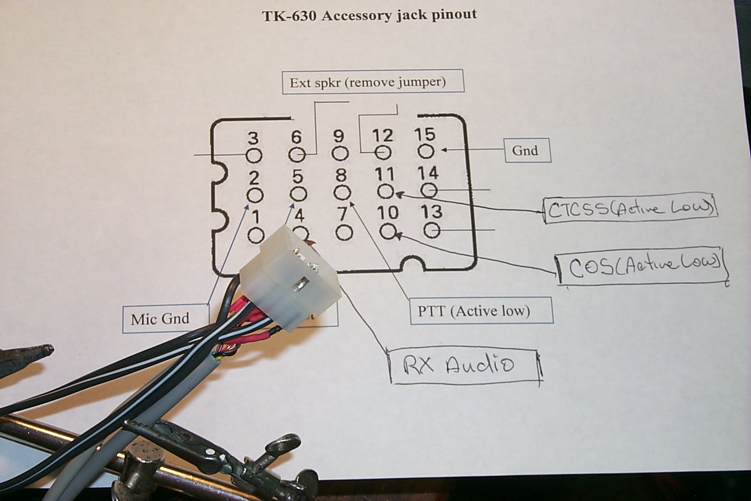
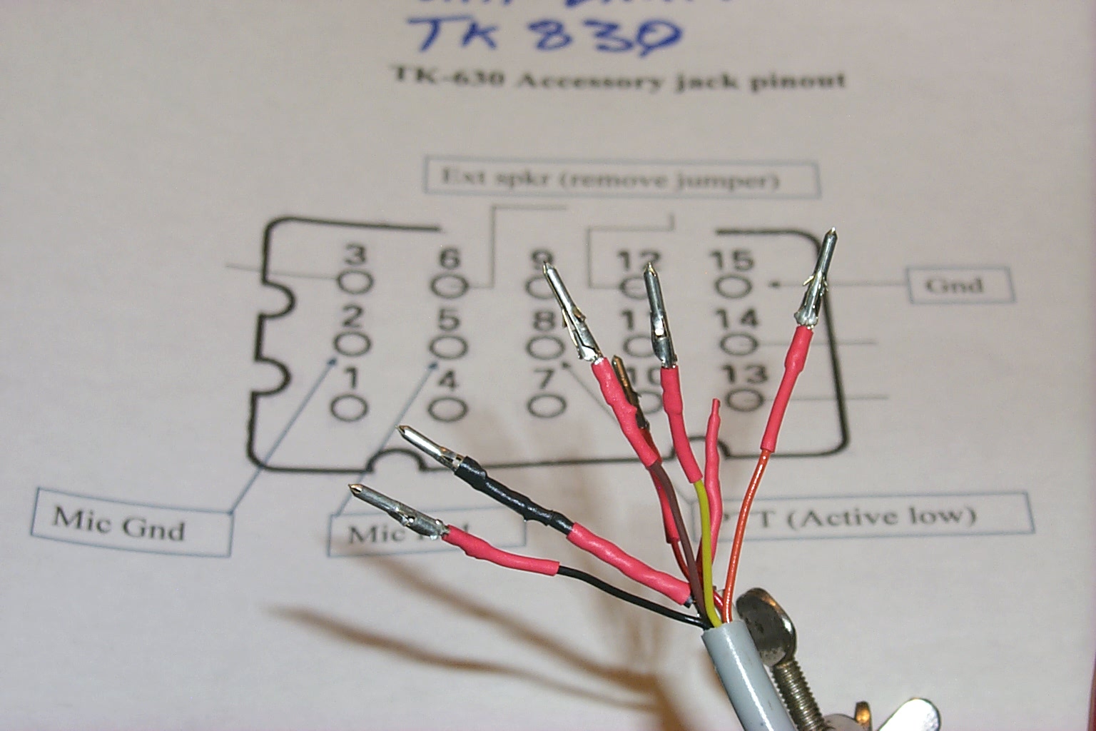
You add a wire to PIN 4 of the main IC in the center of the board to a transistor (just to protect the radio from anything the controller might do wrong) and I cut the brown wire running to the 15 pin connector on the back of the radio to pass the CTCSS signal to the controller. You can then program the software for CTCSS or DPL decode and this line will signal the controller when the correct tone has been decoded by the receiver.
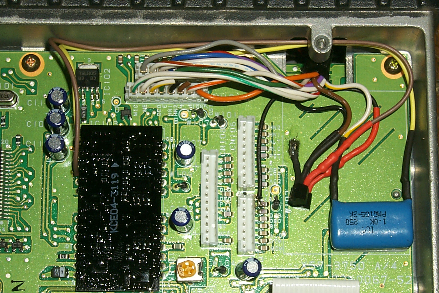
(click on images to enlarge)
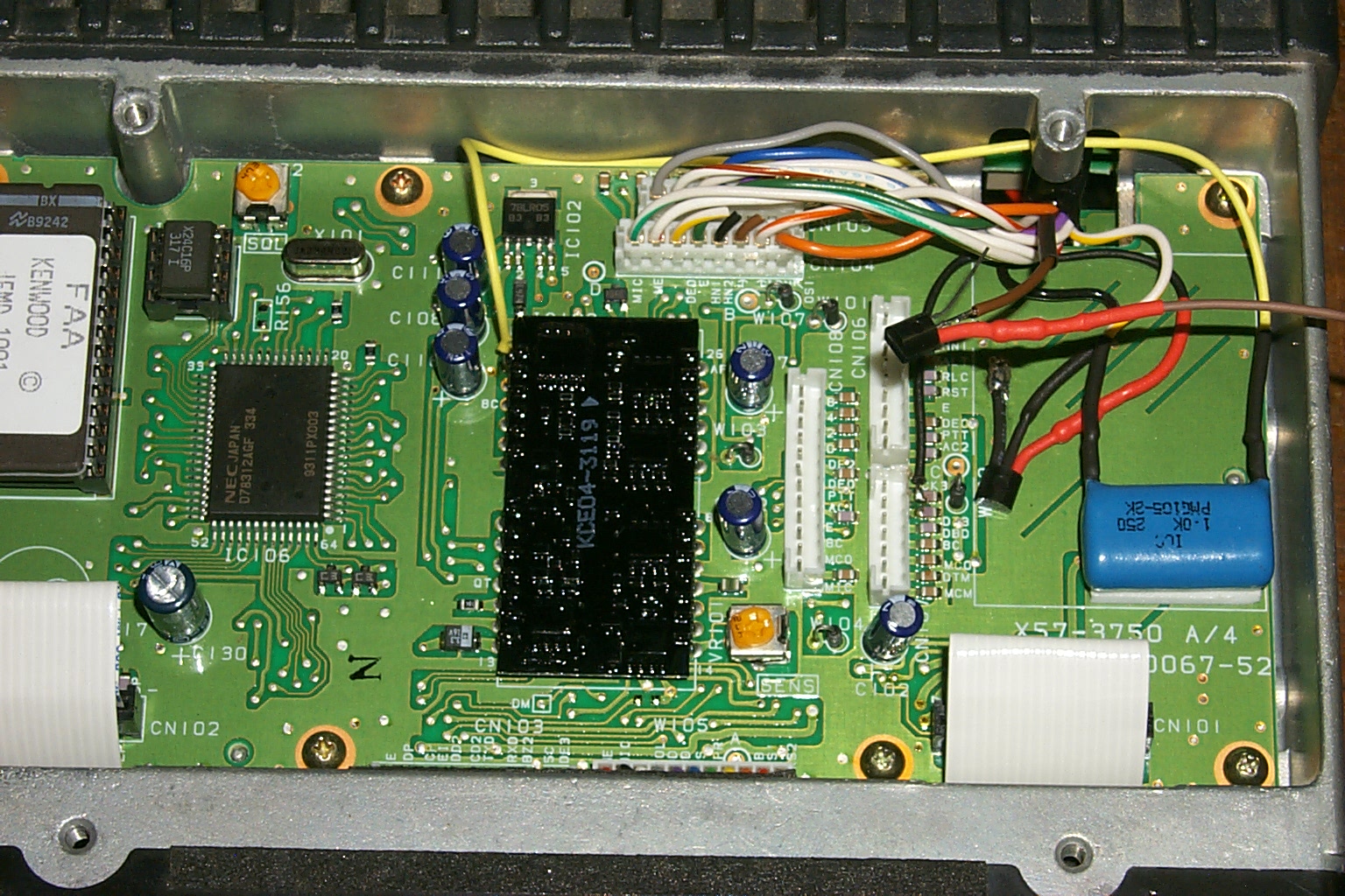
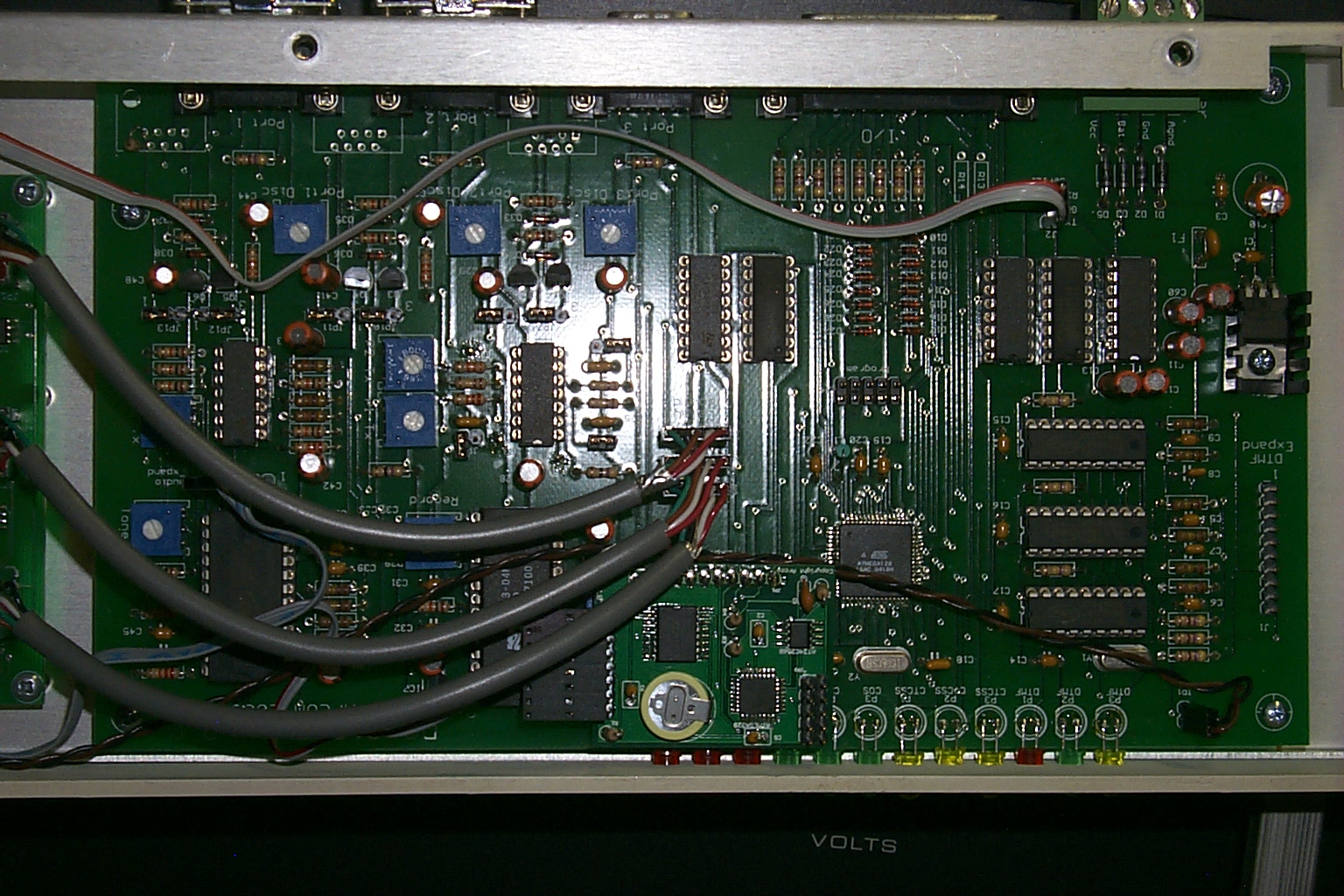
The COS signal is the same simple transistor circuit connected to top pin of Molex header CN107 (CK3) where I used a black wire and routed the signal to the 15 pin connector on the back of the radio using the black wire. This will signal the controller when there is a signal present on the receiver independent of any CTCSS or DPL tones programmed into the radio.
ABILAB's Notes: For the CTCSS I mounted an external transistor in the unused space as shown. There's enough space there to mount a whole lot of stuff, and the wires that you see entering the compartment are (conveniently) the wires from the Accessory connector on the back of the radio. The added resistor is 51K and the transistor is any NPN. The emitter is grounded (that's the scraped area in the picture.) The resistor connects pin 4 of the lump-like "IC" to the transistor's base. The collector is your logic output. If the controller doesn't have a pull-up, you'll need a second resistor from the collector to 5V logic VCC. Same for COS on CN107 (CK3)
(click on images to enlarge)
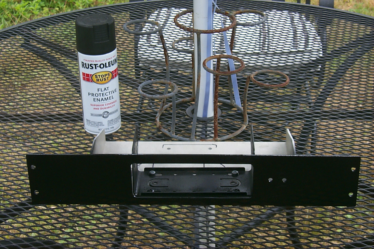
Making it fancy...
A little flat black Rust-Oleum goes a long way to make the custom rack mount for the UHF link radio look very nice. After drilling holes for two toggle switches that will control the link radios PTT line and external speaker I washed the rack mount and gave it two light coats of flat black paint.
(click on images to enlarge)
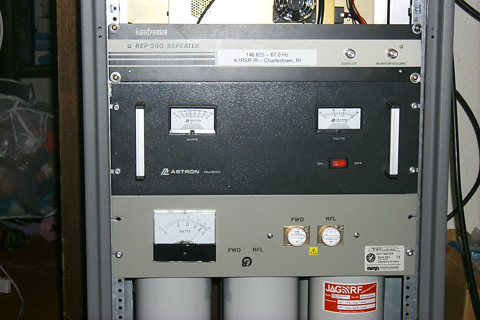
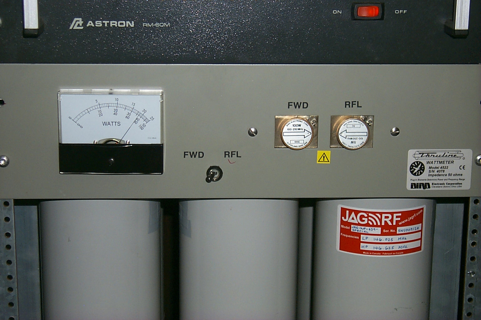
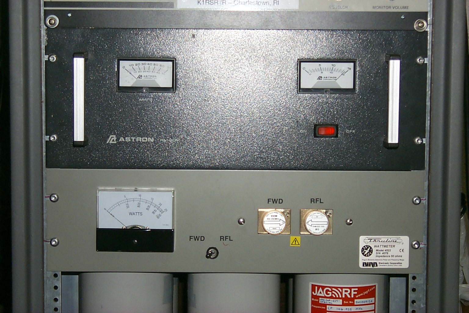
We need more power captain!
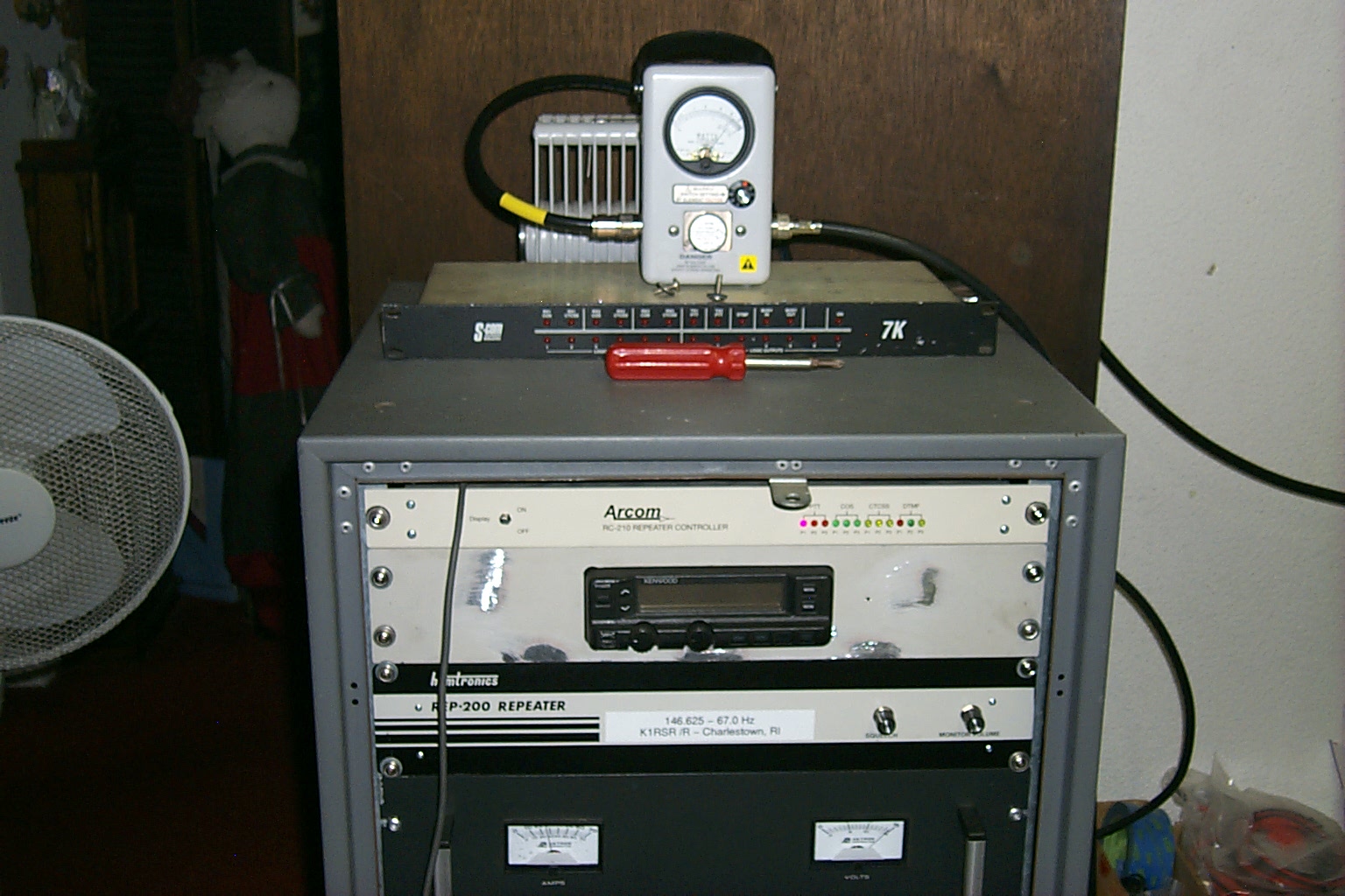
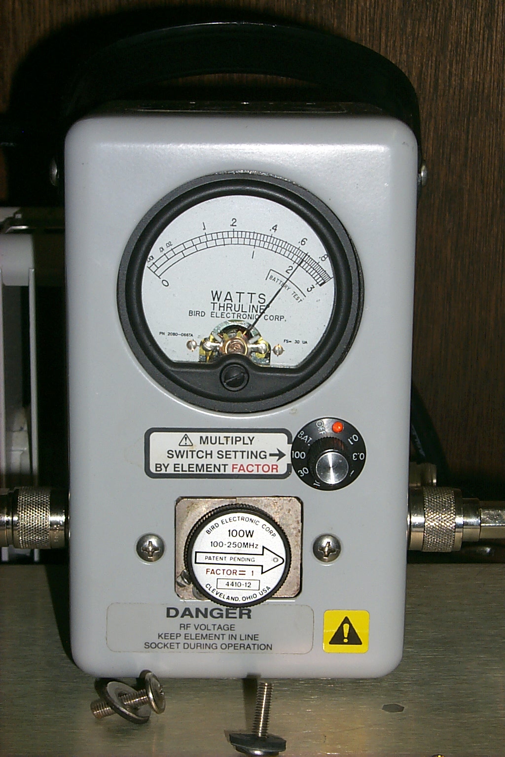
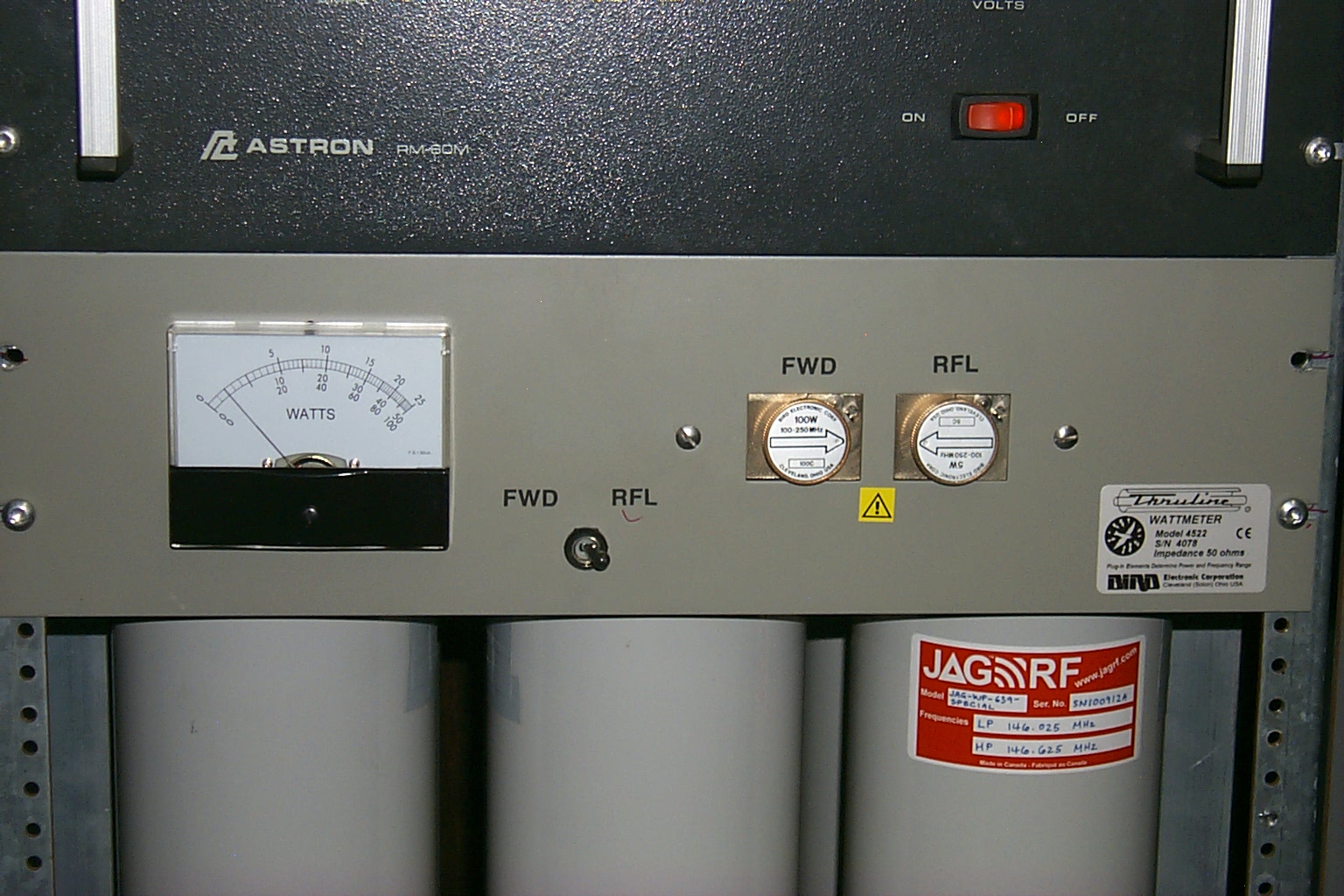
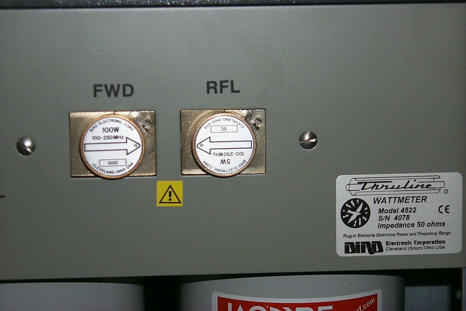
While the paint was drying on the UHF rack mount I also installed a rack mounted Bird VSWR bridge in the cabinet that will monitor the antenna systems performance at a quick glance. The Bird 4522 Dual Line Section Panel Mount with both 5C and 100C Type 43 elements will indicate the repeater forward and reflected power into the repeater antenna.
(click on images to enlarge)
I made a 1/2 wave jumper at 146.625 MHz to connect from the output of the duplexer TEE connector to the input of the Bird 4522 meter in an attempt to keep the impedance as close to 50 ohms as possible. With the 1/2 wave jumper the meter was reading 72 watts forward power with .2 watts reflected power for a VSWR of 1.11 : 1 which is the best match that I have seen on any of my repeaters.
(click on images to enlarge)
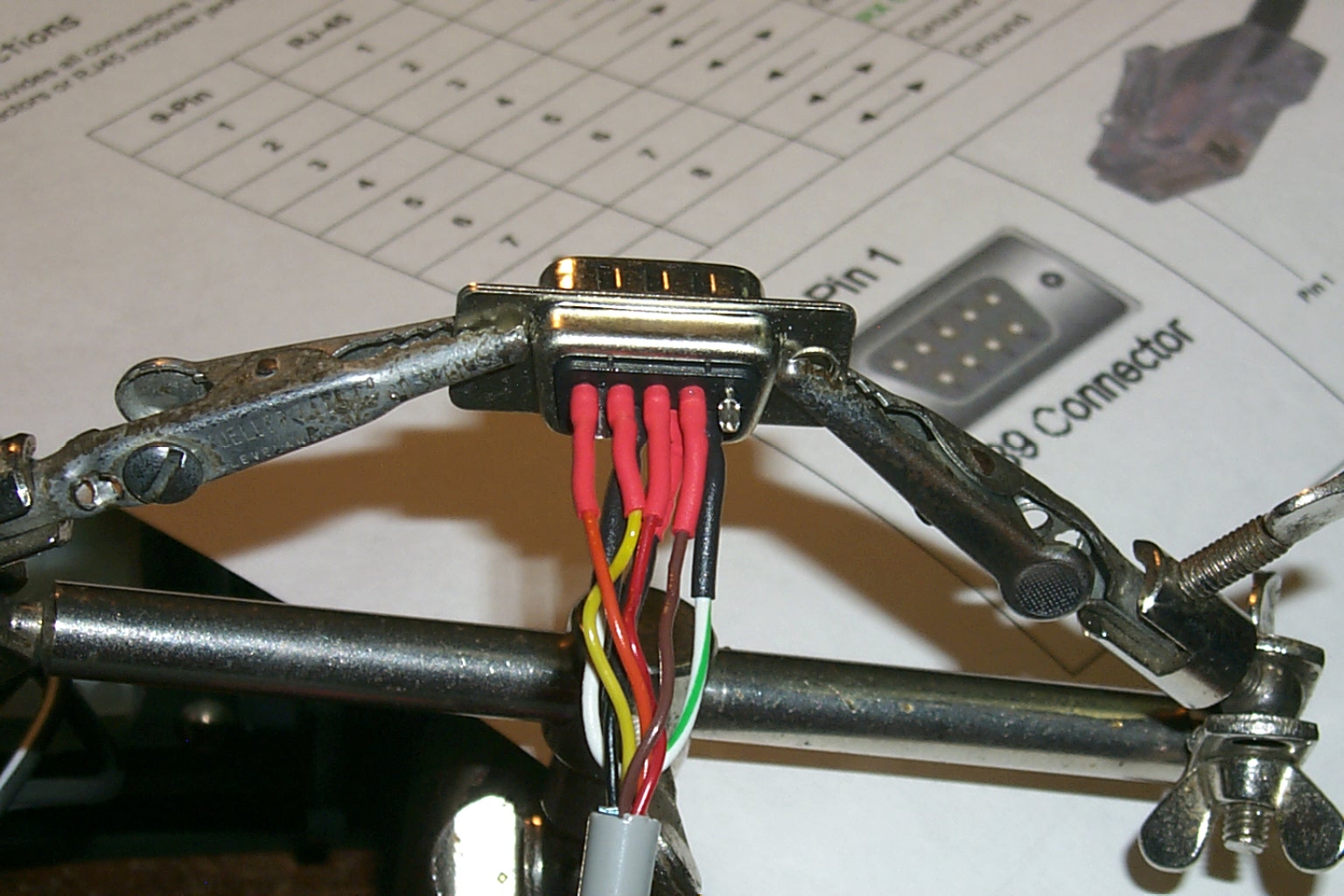
Link me baby...
Making the controller cable for the UHF link radio was very simple, just connect all the goes ins with the goes outs, and all the goes outs with the goes ins. I also configured two toggle switches to control the UHF link radios receiver speaker and PTT line for transmit locked on (test mode), transmitter disable, and transmit via the controller (normal mode).
(click on images to enlarge)
Clock Not Set...
One of the exciting "features" of the RC-210 controller, it does not retain the time and date in non-volatile memory when the power is turned off. After hearing the controller announce "clock not set" a few dozen times I ordered the RTC option which is a real time clock for the controller. Once installed the RTC retains the current time and date when the controller is powered down.
(click on images to enlarge)
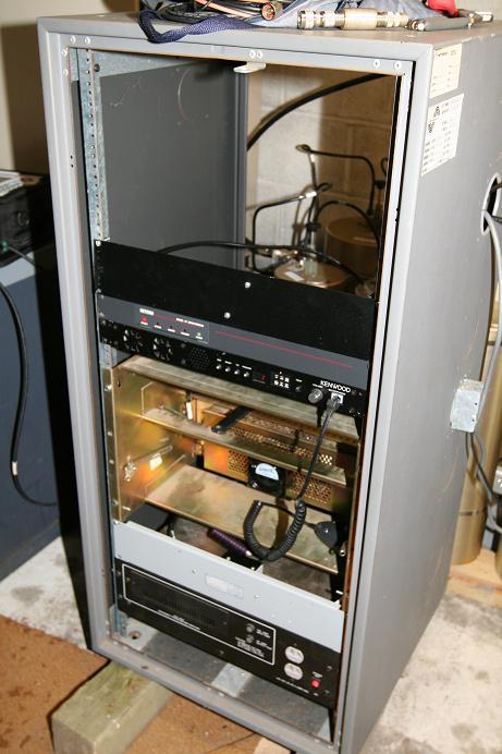
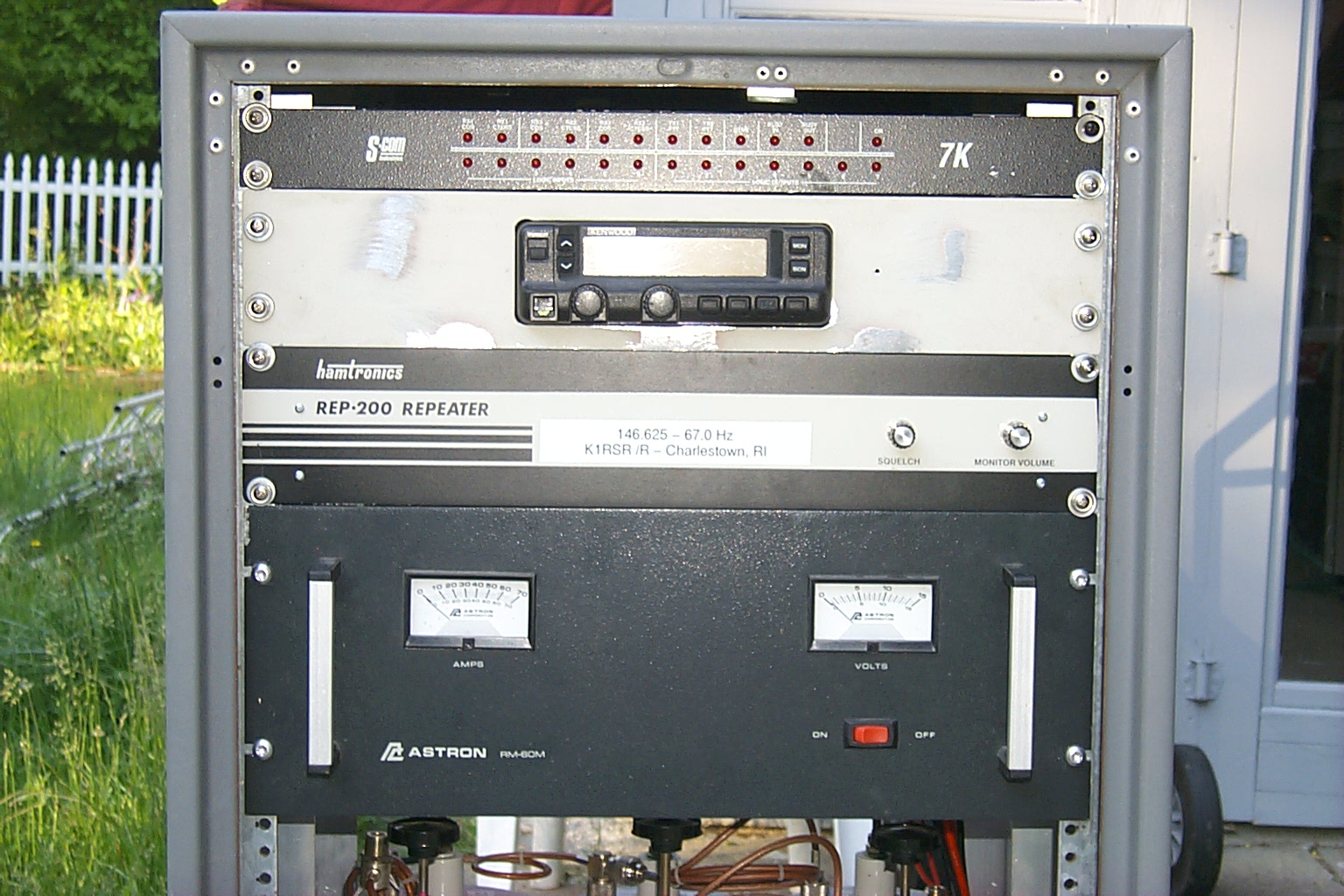
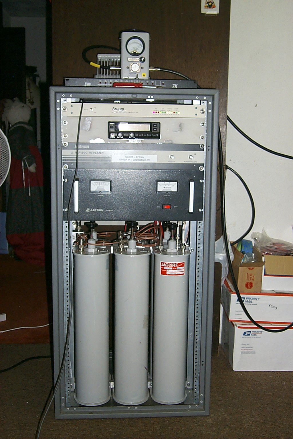
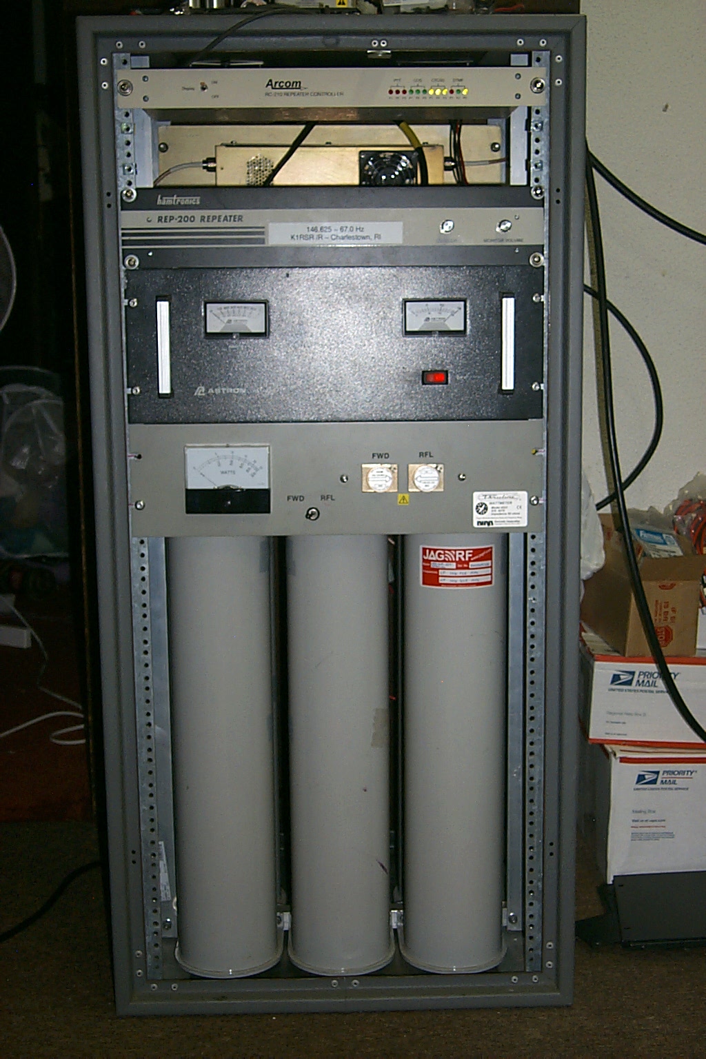
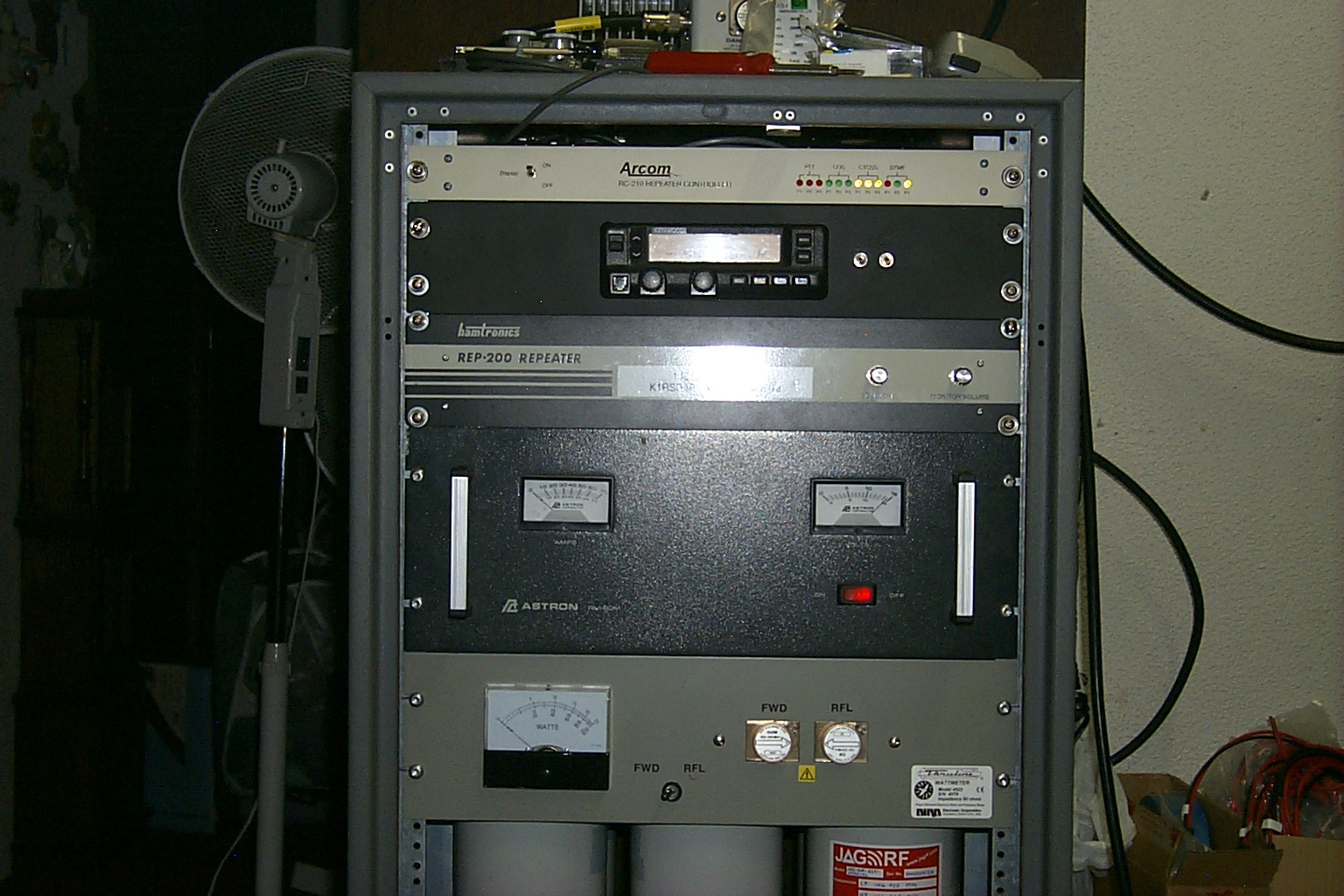
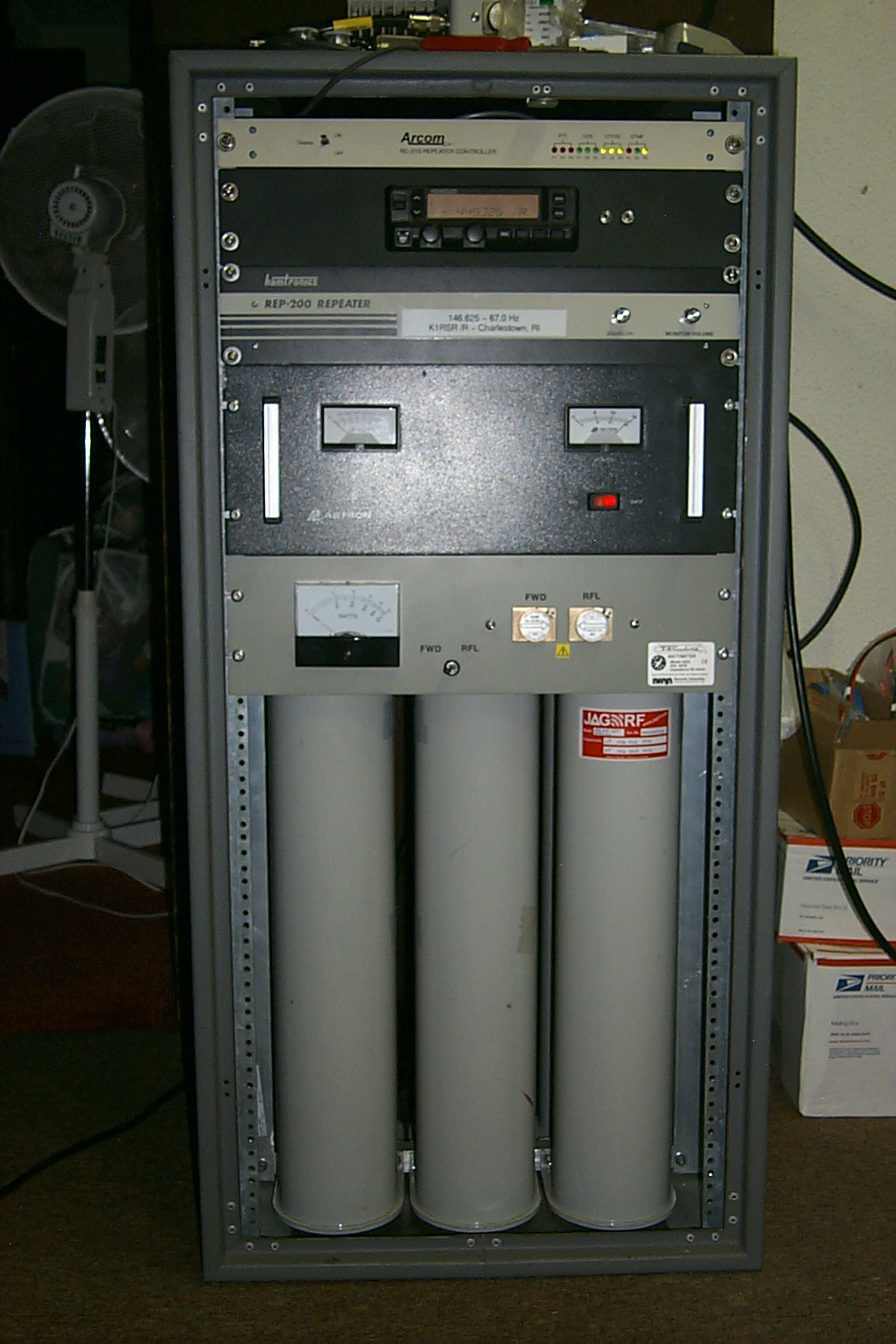
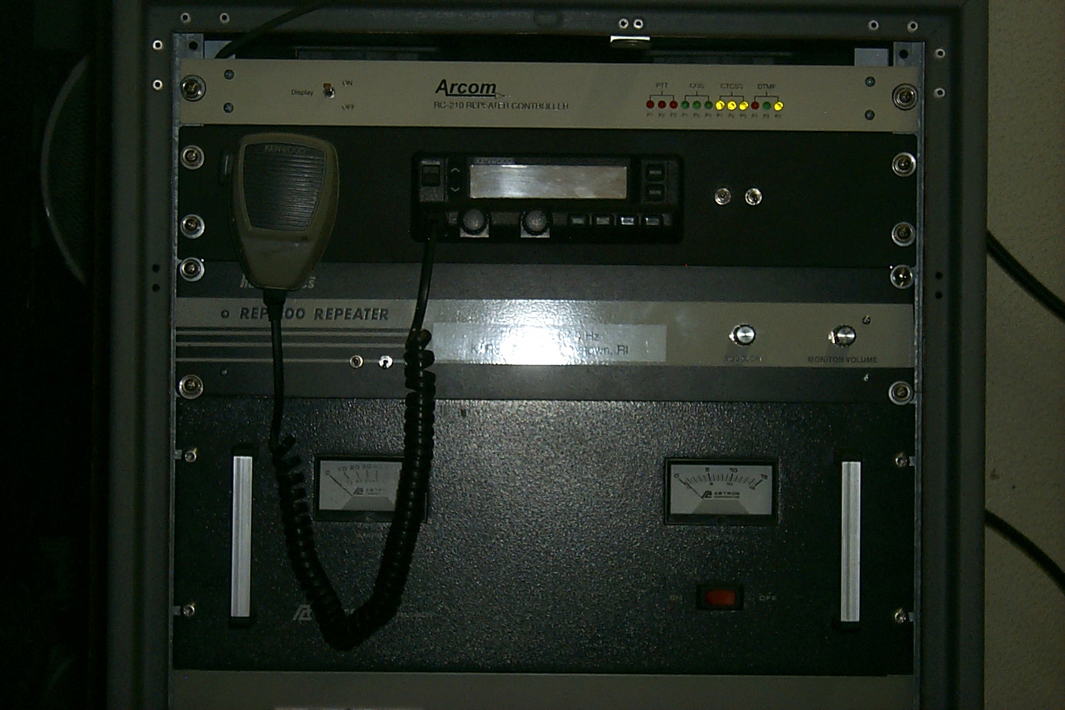
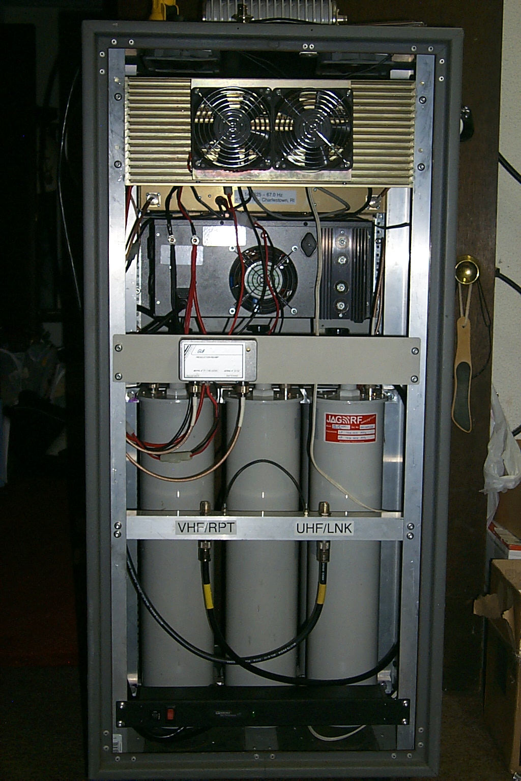
The big box that is going beep...
With the UHF rack mount painted, and everything bolted into the rack cabinet, the beeping box is starting to look like the real deal. The repeater has been on the air now for a month and initial testing has been very successful. Only a few more items to complete, mounting the Poly-phasers for lighting protecting, a surge protected plug strip for power in the cabinet, and a final audio adjustment with a spectrum analyzer to make sure all the levels are within specifications.
(click on images to enlarge)
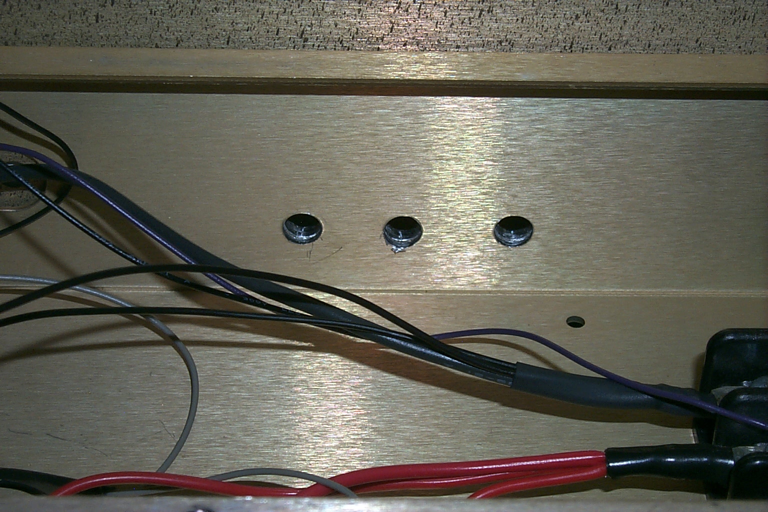
The last few things...
I drilled three holes in the front of the Hamtronics RF deck and installed toggle switches to control the PTT and CTCSS encode on the transmitter, and the CTCSS decode on the receiver. I also installed a clip to hold the microphone for the UHF link radio.
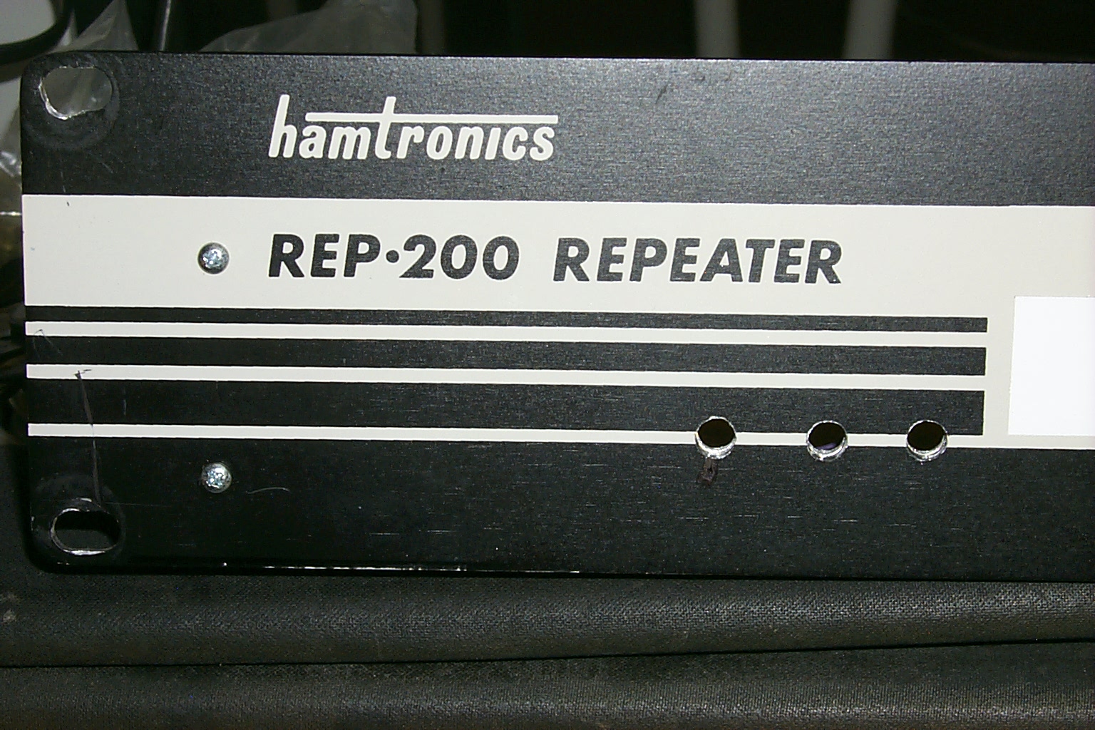
(click on images to enlarge)
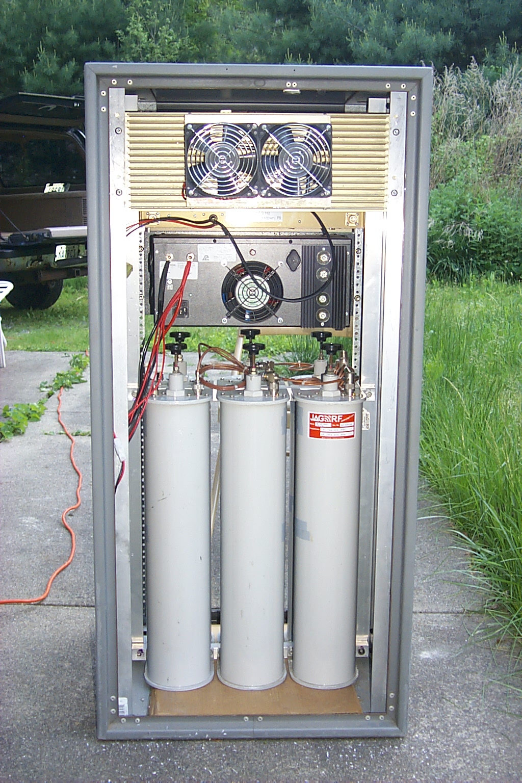
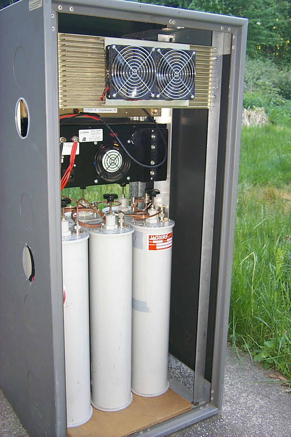
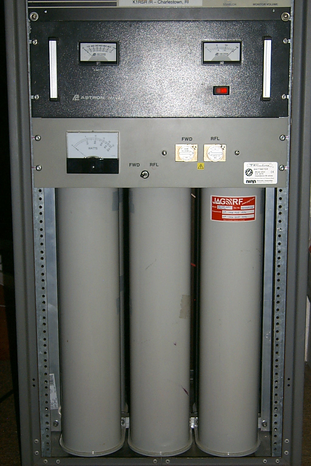
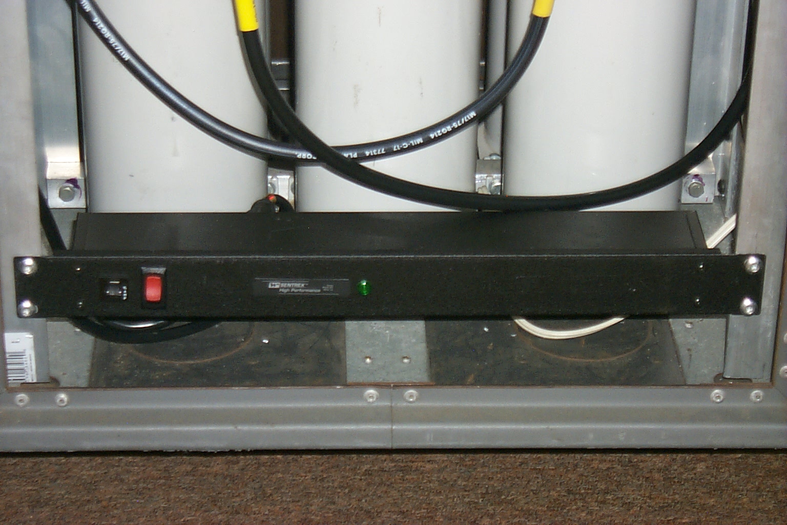
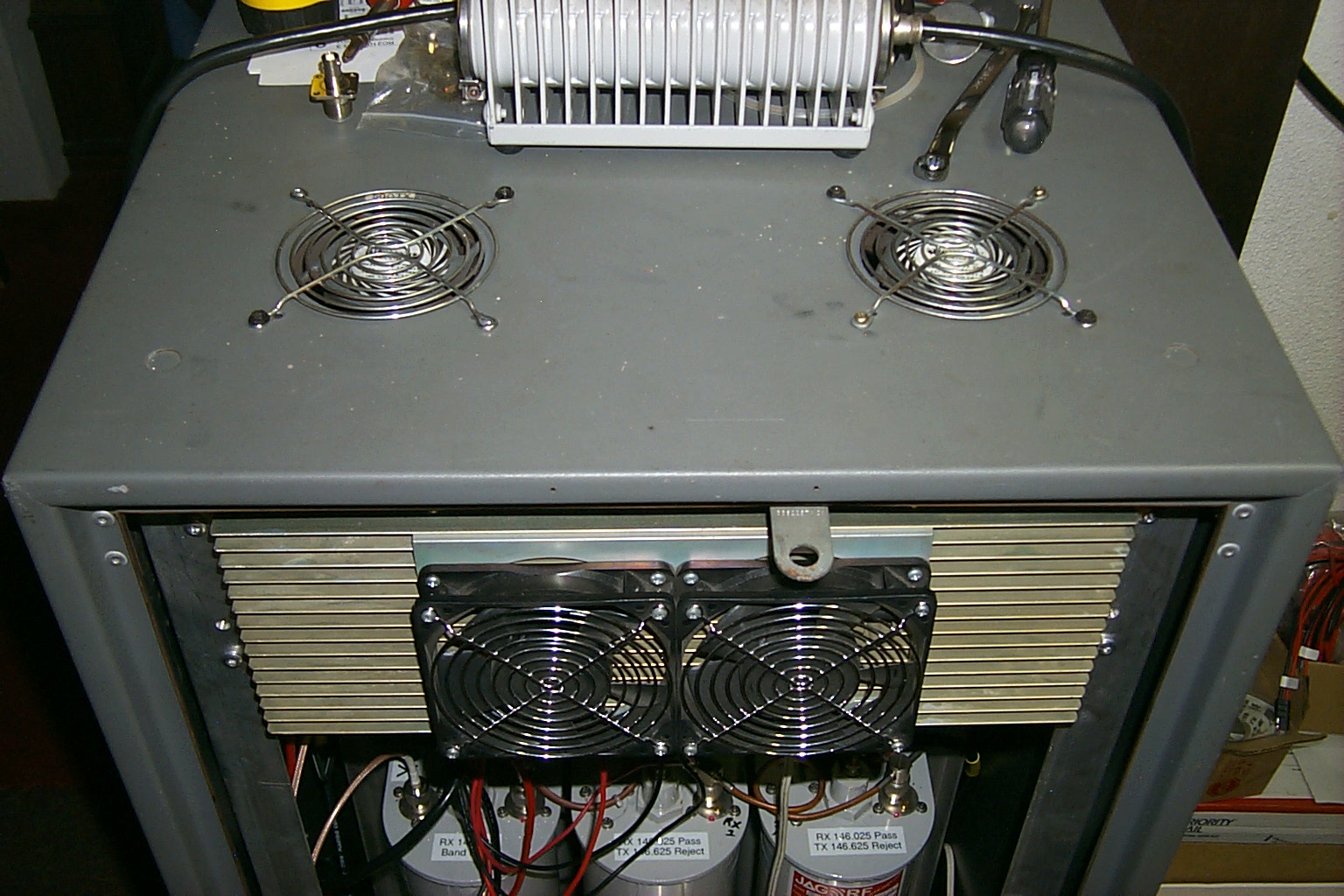
Then I installed a power strip at the bottom of the rack cabinet in the back, mounted to Poly-phasers for lighting protection, and added two additional AC fans for some extra cooling. These two fans cycle on and off by the RC-210 controller. Both the 60 Amp DC power supply and he Henry power amplifier have fans that are controlled by thermostats and they cycle on and off as needed.
Back on the air...
Saturday morning August 30th at 8:00 am ET the Legacy K1RSR analog repeater went back on the air.

Return to the KA1RCI Repeater Network Home Page
This page was last updated on
08/31/2014 and it has been viewed times.
Send mail to [email protected] with questions or comments about this web site.
Copyright 1995-2014 Steven M Hodell
Copyright in these pages, in the screens displaying the pages and in the information, materials and other content contained in this web site is owned by Steven M Hodell unless other wise indicated and is protected by U.S. and international copyright laws and treaties. The information, materials and other content of this web site may not be copied, displayed, distributed, downloaded, licensed, modified, published, reposted, reproduced, reused, sold, transmitted, used to create a derivative work, or otherwise used for public or commercial purposes without express written consent.