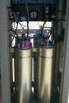
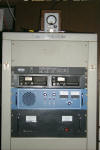
147.075 / 147.675 with PL 67.0 Established 2005
Portsmouth - Rhode Island
The Oh Seven Five gets a face lift in May 2014 scroll to the bottom for the latest updates or continue from here for the full history...
Here is the gang responsible for this node on the network, Bill KA1VKD, Jeff WA1VQY, John WA1ABI, and Steve KA1RCI
(click on image to enlarge)
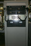
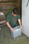
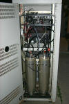
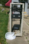
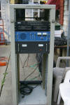
When Jeff WA1VQY suggested that we add a node to cover Aquidneck Island Steve KA1RCI jumped at the chance, with expert guidance from John WA1ABI we cobbled together some old Kenwood hardware with some new components and build a nice machine. Using four Kenwood TK-30 series radios we built a full duplex VHF repeater with a half duplex UHF link and a six meter receiver.
(click on image to enlarge)
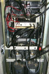
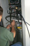
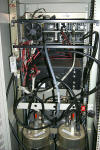
The radios have been modified by replacing the SO-239 chassis connectors with female Type-N connectors and Andrews FSJ2 Heliax was used for all the RF cables.
(click on image to enlarge)
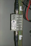
There is a power attenuator installed between the primary VHF transmitter and the VHF PA allowing for a much greater range and control of the output power.
(click on image to enlarge)
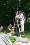
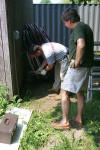
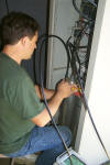
John and Jeff making sure we have a good ground system installed.
(click on images to enlarge)
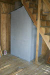
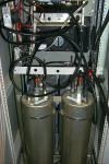
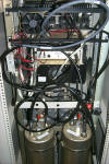
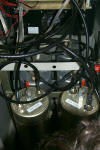
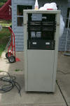
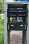
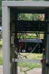
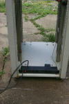
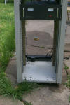
A water tight "vault" was constructed to keep the hardware dry and secure.
(click on image to enlarge)
Duplexer reconfiguration December 2008
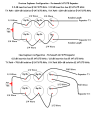
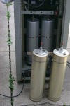
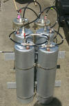
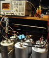
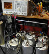
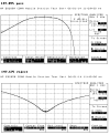
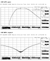
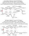
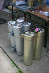
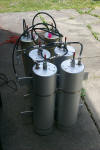
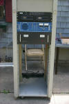
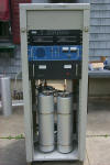
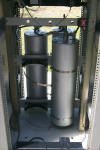
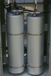
In the original configuration the duplexer had four Sinclair Band Pass / Band Reject cavities and two smaller Decibel Band Pass cavities. In this first set of images you can see that the cavities were not optimized for the center frequency and could use some tweaking.
(click on images to enlarge)
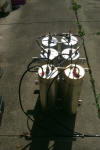
The photos below show the duplexer after the smaller Decibel cavities were replaced with a pair of matching Sinclair Band Pass cavities and all six of the cavities were retuned.
(click on images to enlarge)
Duplexer reconfiguration December 2010
Saturday morning October 2010 Roland N1JOY and Steve KA1RCI reconfigured the Portsmouth 147.075 duplexer in the new 2 x 4 setup that we have been deploying at all the other sites. We have been moving both band pass cavities over to the receiver path and only running two BP/B cavities on the transmitter path.
After taking our initial before measurements of the duplexer in the original configuration we removed all the 1/4 wave cables on the band pass cavities and random length jumper cables connecting the transmitter and receiver to the duplexer, and replaced them with 1/2 wave and full wave cables cut for the 147.075 / 147.675 frequency pair.
(click on images to enlarge)
After getting all the cavities retuned with the new cables and configuration Roland made a few final adjustments to the reject notches and we were done. The new duplexer configuration gave us a 1 dB improvement on the reviver path and just over a 2 dB improvement on the transmitter path.
(click on images to enlarge)
The before and after numbers...
(click on image to enlarge)
The Oh Seven Five gets a face lift in May 2014
Or, watch while I pour a dump truck full of cash into the repeater!
In the spring of 2014 the Portsmouth Oh Seven Five started acting up, the transmit power was intermittently going into very low or "flea power" and then coming back to full power without any technical intervention. It was later discovered that the Polyphaser (device that protects the repeater from lighting strikes) had failed, or possibly did its job by sacrificing itself during a nearby bolt of lighting, and all of the transmitters power was being reflected back into the repeater. This was most likely causing the high VSWR circuit in the power amplifier to switch the PA offline causing the mystery high power lower power phenomena.
After a quick trip to the site, Roland N1JOY, Brian N1BS, and Steve KA1RCI were able to determine that the Polyphaser was at fault. Roland swept the transmission line with an analyzer that clearly showed a large "spike" approximately two meters away from the duplexer, right where the Polyphaser is located. Unfortunately the repeaters power amplifier was also damaged and no longer working.
The decision was made to take this opportunity to rebuild the nearly ten year old repeater with some new hardware. We loaded up the repeater and brought it back to KA1RCI's QTH in Lincoln where he could dismantle the repeater and start rebuilding from the ground up.
Tearing it all apart...
With the repeater back home in Lincoln Steve KA1RCI started the disassembly. Pulling out the damaged PA, removing the filter cavities, and cleaning out a decade of mice droppings out of the bottom of the cabinet was oh so much fun. Why is it that mice love to poop on all of my repeaters?
(click on images to enlarge)
De Poop'n
Several hours of scrubbing with bleach and burning hot water all the evidence left behind by the mice has been eradicated! The cabinet is clean again and smells much better now...
Oh yet, I hates those mices to pieces!
(click on images to enlarge)
The new RF deck - ACS-6000
The original Kenwood TK-730 radios that had been the transmitter and receiver were replaced with a new ACS-6000 repeater and the S-Com 7k controller was replaced with a new S-Com 7330 controller.
(click on images to enlarge)
Duplexer reconfiguration May 2014
My friend Jag from JAG RF has been working with me for many years and help me learn a great deal about how duplexers work, how the cavities interact with each other, and how the cable length of the jumpers in the phasing harness can affect the filter cavities performance.
Again, taking this opportunity with the Polyphaser failure and rebuilding the repeaters hardware, we decided to re-configure the duplexer back to a 3 x 3 setup with a new custom phasing harness cut to the 147.075 / 147.675 frequency pair that Jag made in his lab.
(click on images to enlarge)
Brian N1BS retuned the Oh Seven Five filter cavities in his lab using his HP E8285A tracking generator / spectrum analyzer and the new custom phasing harness from JAG RF.
(click on images to enlarge)
The cavities tuned easily with the new custom phasing harness from JAG RF.
It seems to work well, very low
measured insertion loss. Reject is moderate, in line with a 4-cavity BpBr
duplexer. Sinclair specs 80 dB rejection for their 4-can set, so we beat
that on both sides. I'm not sure exactly what the extra bandpass cavities
bring to the party, but we will see how it works out.
(click on images to enlarge)
Cabling the new S-Com 7330 controller
While Brian N1BS was working on the duplexer in his lab, Steve KA1RCI starting building the new control cables to interface the ACS-6000 VHF repeater, Kenwood TK-830 UHF link radio, and Kenwood TK-630 Six Meter receiver to the new S-Com 7330 controller.
(Insert controller cable photos here)
The replacement Henry power amplifier
The original TE-Systems power amplifier, that fell victim to the high VSWR / Polyphaser, was purchased second hand back in 2004 for the Portsmouth repeater, however it was configured and tune for 158 MHz so it never really preformed very well at 147 MHz, and sometimes even caused some issues. It will be sent back to the manufacture for repair / retuning down to 147 MHz and become a spare for the repeater network. In order to get the repeater back online as quickly as possible, a new Henry C250AB30R power amplifier was ordered, and custom tuned for 147.075 MHz.
There is nothing like the smell of a brand new power amplifier...
(click on images to enlarge)
Mounting the power amplifier
The new Henry PA mounts differently than the TE-System PA that blew up so I had to move all the new hardware around in the rack cabinet to fit everything in. The extra set of rails that I had installed during the original build to mount the duplexer went all the way to the top of the cabinet and there was enough room to fit the new PA so I decided to mount it on those rails. The new PA was wider than the space between the rails to I had to remove them and have my brother-in-law cut out notches to fit the PA.
(click on images to enlarge)
(click on images to enlarge)
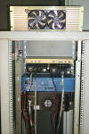
One the new PA was mounted I also installed a set of cooling fans that will direct air flow over the link radios.
Putting it all back together...
With
all the new hardware cabled, configured, programmed, tuned, and tested it
was time to mount everything back into the repeater cabinet. Most of the
hardware would bolt right back into its original locations but a few of the
components like the new power amplifier would need some mounting rails
fabricated.
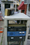
During the initial testing phase summer finally kicked in and it got HOT. My little office / radio shack was as hot as a pizza oven and having the repeater running in that little space didn't help one bit. I needed to efficiently move air through the repeater cabinet to keep all the components cool.
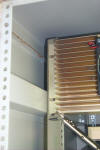
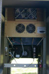
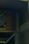
I decided to install some AC fan enclosures that had been donated for the repeater projects. I had two rack mount units each with three 4 inch AC fans. The first unit bolted right into place in the back of the rack just about the middle which would draw air in through the vents in the back cabinet door and direct air flow up towards the top of the cabinet.
The second unit would fit in the space available at the top of the repeater cabinet in the front however there was no way to mount it with the existing rack mounts. First I removed the rack mounts from the fan unit, then I took it apart and fabricated a mount using the blank panel that was covering that empty space in the cabinet.
Using the fan enclose as a template I transfer the fan opening locations onto the blank panel and then drilled mounting hold to secure the fan enclosure to the plate and cut out opening to allow the air to pass through.
With the AC fan enclosure mounted to the rack plate, now modified with three big holes, the fans were able to exhaust any hot air out the front of the repeater cabinet keeping all the hardware inside nice and cool.
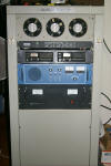

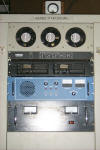
Back in the vault!
![]()
Return to the KA1RCI Repeater Network Home Page
This page was last updated on
06/26/2014 and it has been viewed times.
Send mail to [email protected] with questions or comments about this web site.
Copyright 1995-2014 Steven M Hodell
Copyright in these pages, in the screens displaying the pages and in the information, materials and other content contained in this web site is owned by Steven M Hodell unless other wise indicated and is protected by U.S. and international copyright laws and treaties. The information, materials and other content of this web site may not be copied, displayed, distributed, downloaded, licensed, modified, published, reposted, reproduced, reused, sold, transmitted, used to create a derivative work, or otherwise used for public or commercial purposes without express written consent.

