 The KA1RCI Repeater Network
224.040 / 222.440 with PL 67.0 - Established 2007
Lincoln - Rhode Island
Scroll to the bottom for the latest update on 03/24/2012
I am often asked, "Just how many repeaters are enough?"
Well my answer is "One more is always good..."
After moving the 223.960 / 449.325 repeaters from the Lincoln site to Johnston in 2004 I ended up with an unused 220 repeater antenna sitting at the top of the 80 tower in Lincoln. As all good repeater builders know, nature abhors a vacuum, and this void would not last long...
The 224.040 repeater project was conceived when I found a 220 Kendecom repeater for sale with a set of Wacom duplexer all tune up and ready to go on the air.
This was to good to be true... Had I stumbled onto a I "turn-key" repeater?
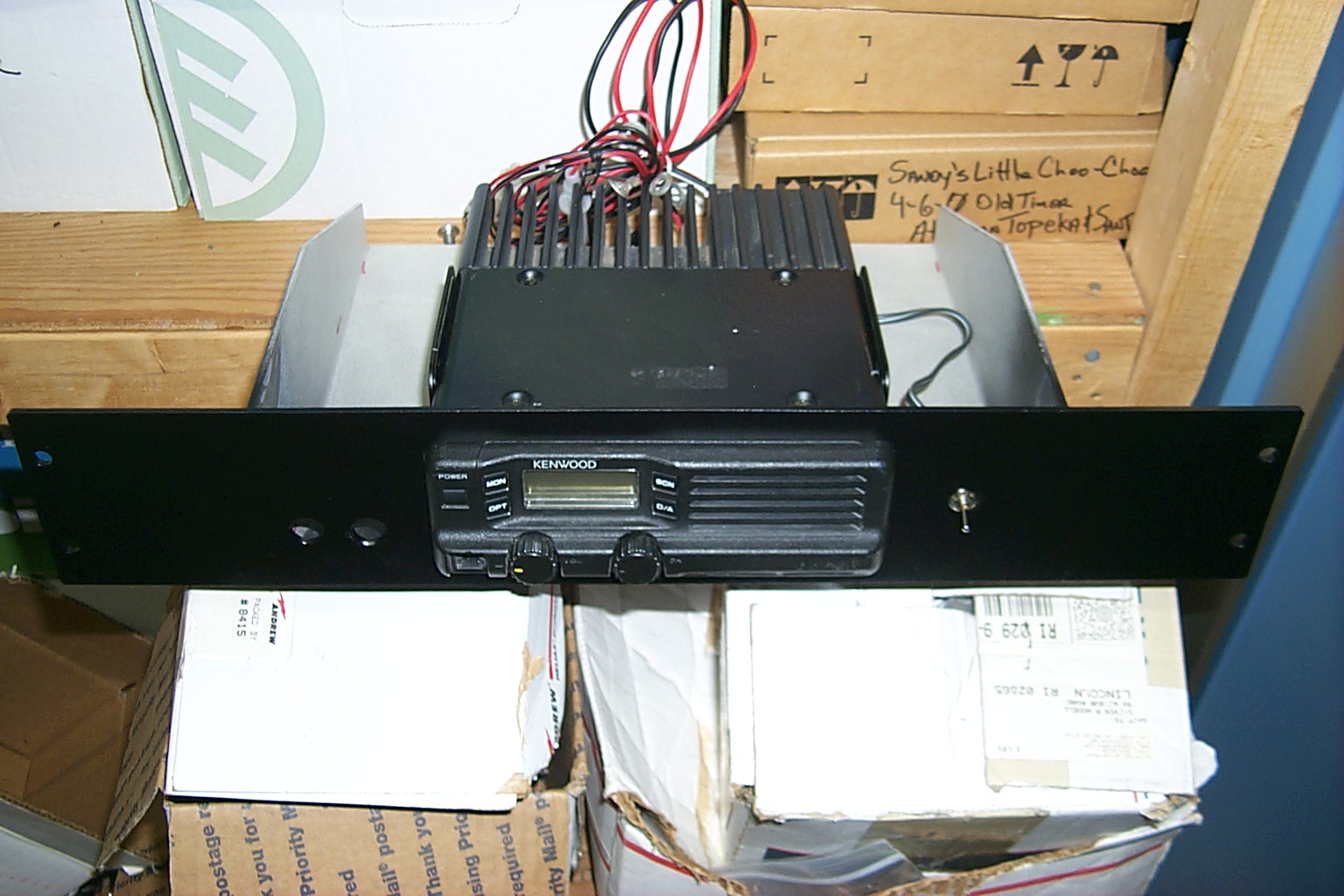
Sure enough it was that easy, when the nice Fed-Ex man delivered my two big boxes that contained the repeater and the duplexer cavities, it was just that simple. I carefully unpacked everything, connected all the cables, hooked up the antenna feed-line and clicked the power switch to the ON position...
BEEP 224.040 was on the air!
It took me longer to sit down with the manual and reprogram the controller with my call and personal system configuration preferences then it did for me to get the repeater running. Sandy and I were talking on 224.040 on her way home from the Southwick Zoo the same afternoon that the repeater had been delivered.
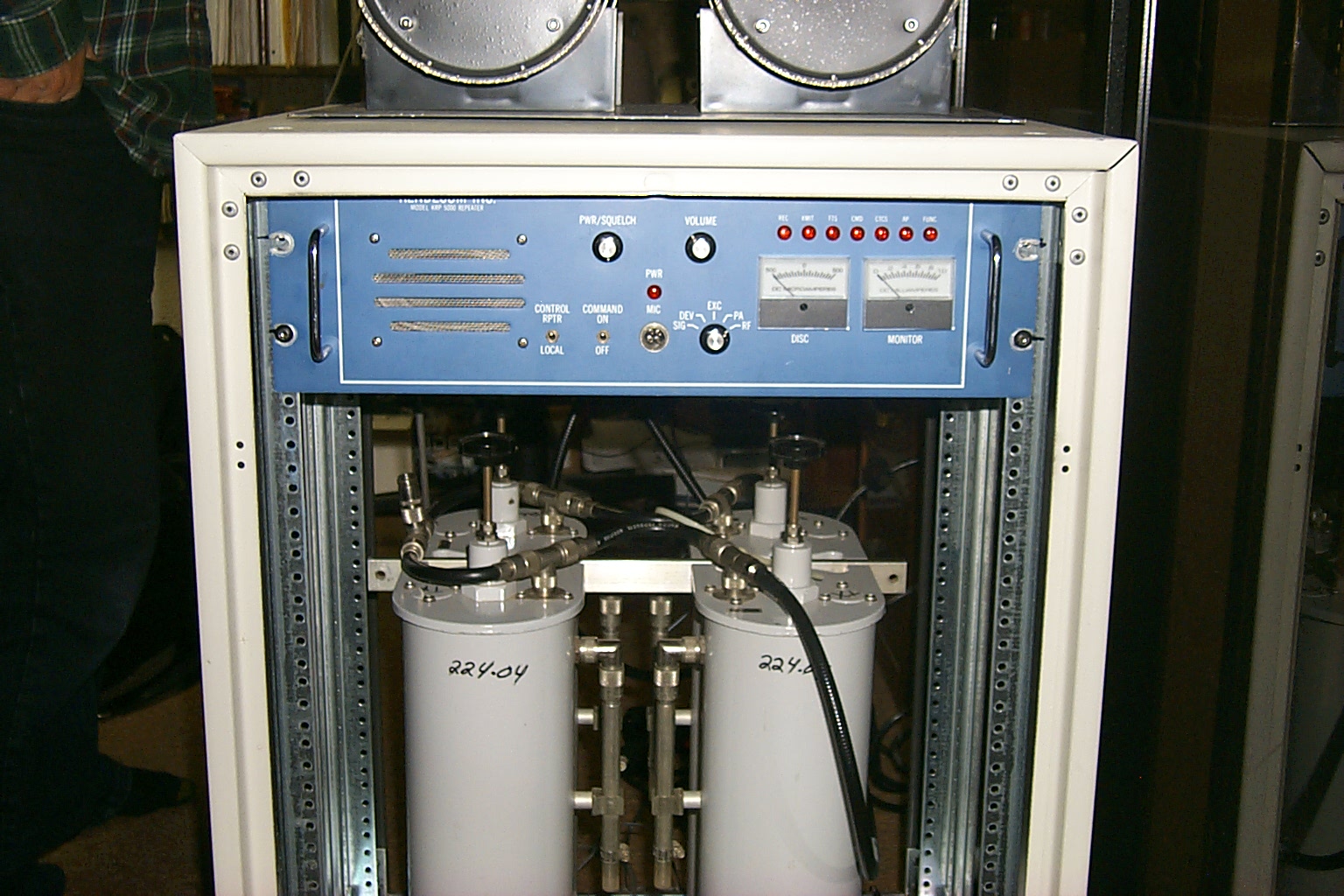
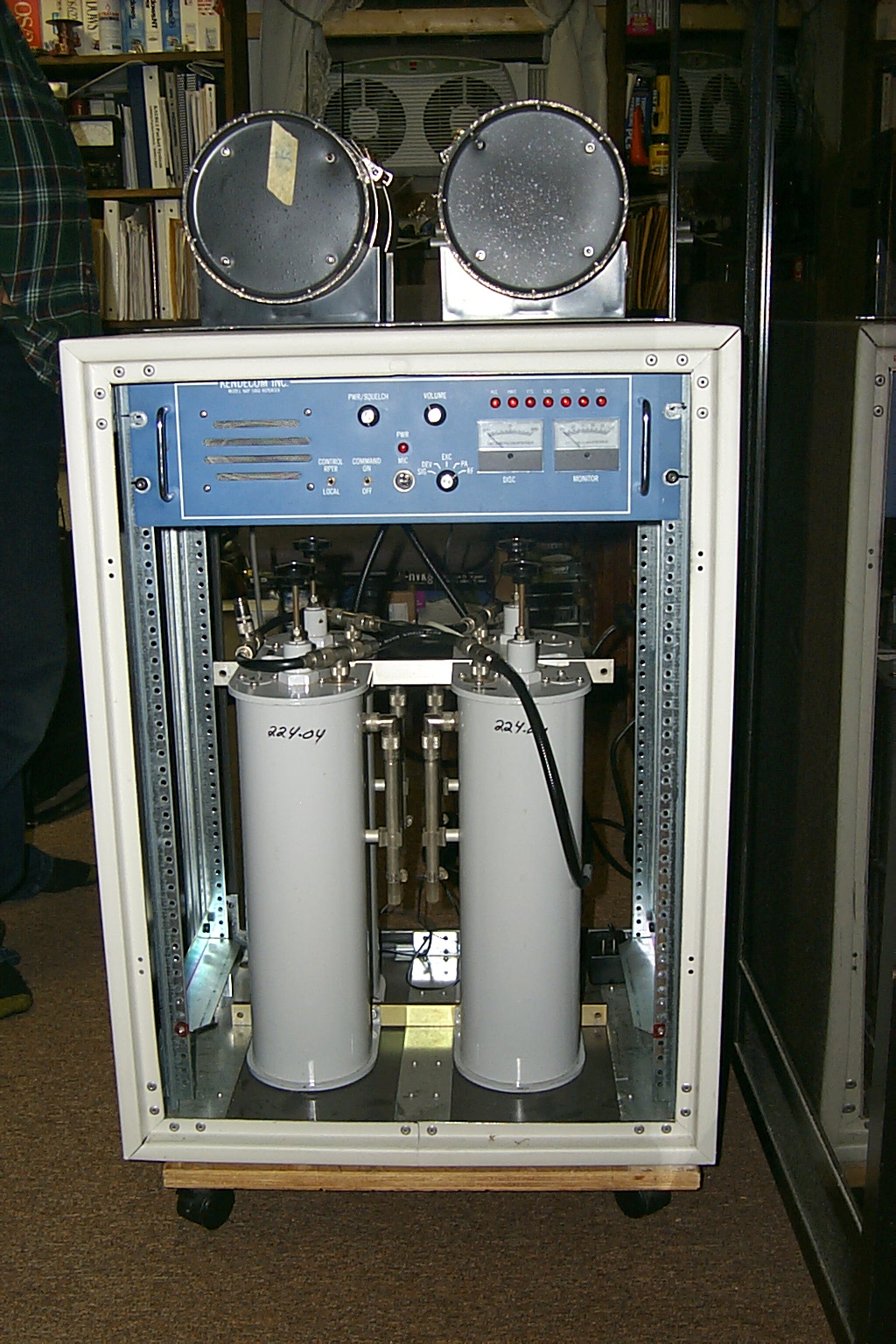
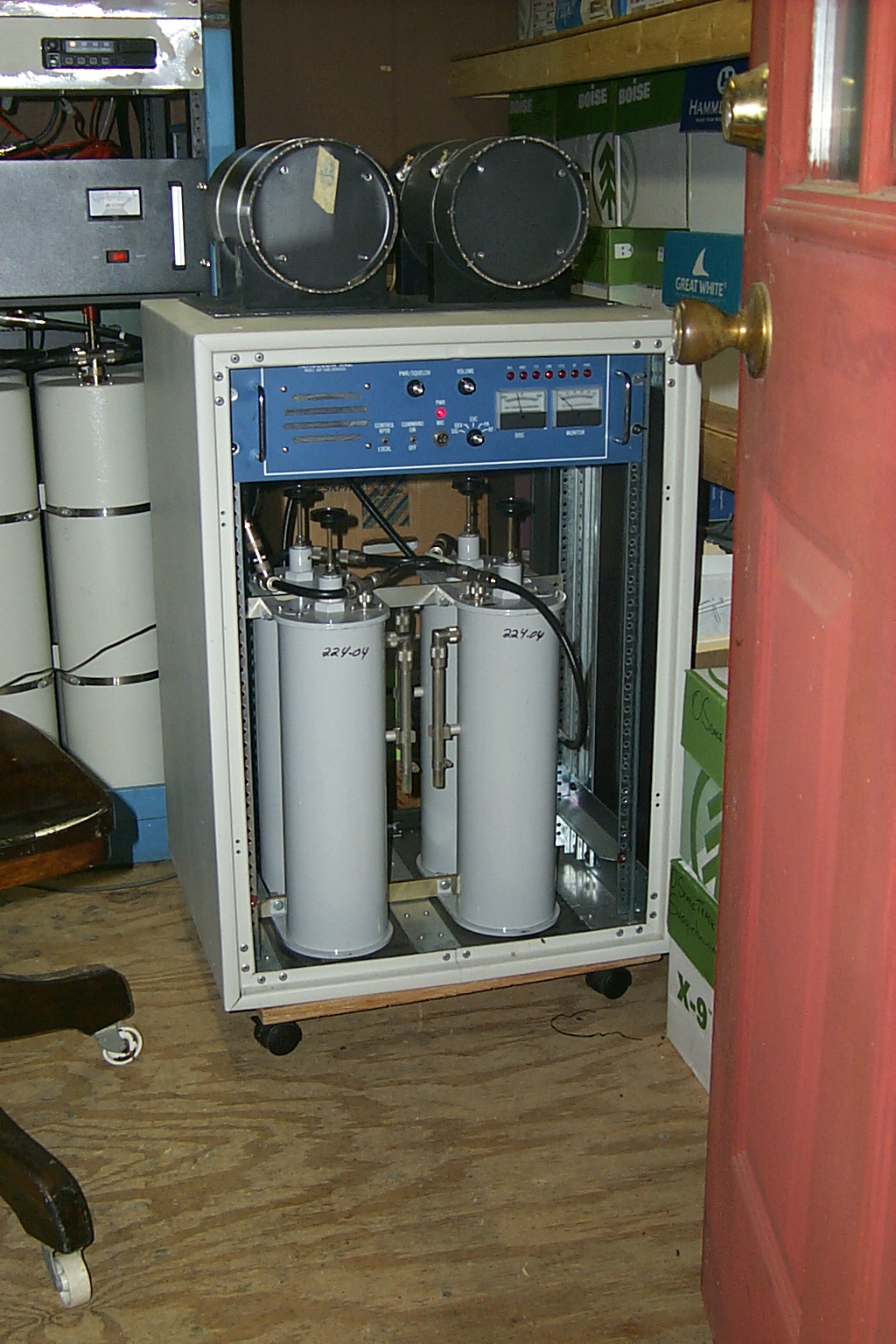
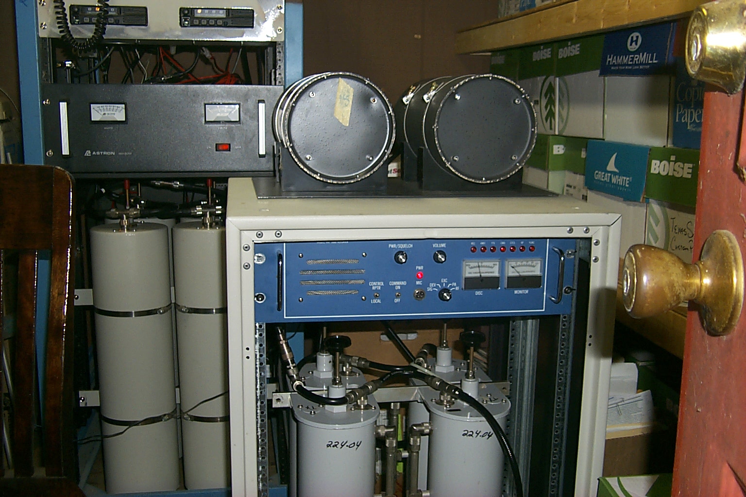
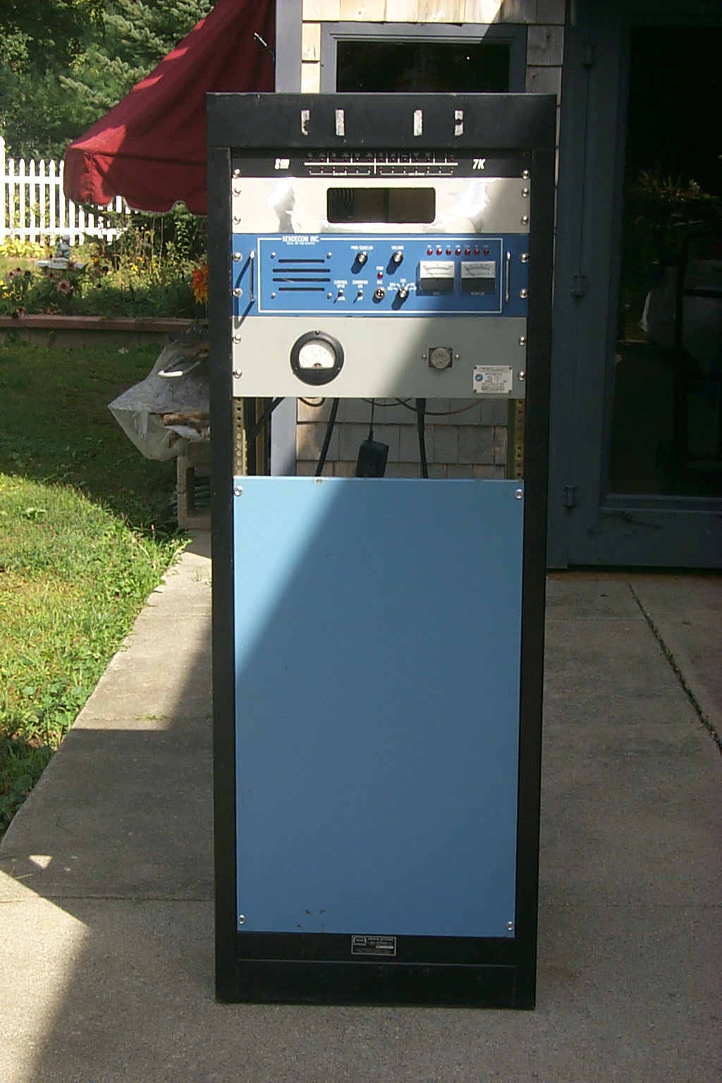
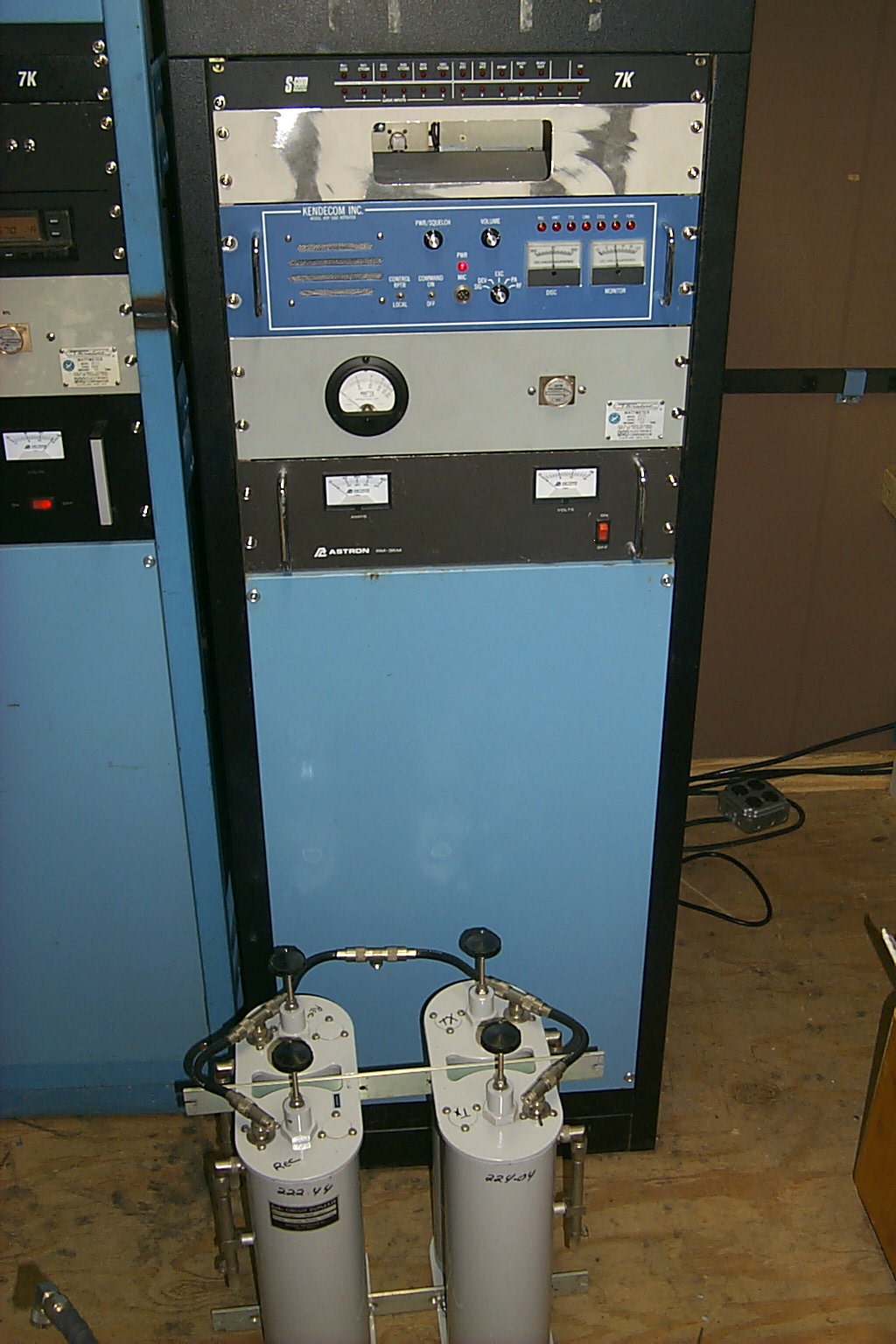
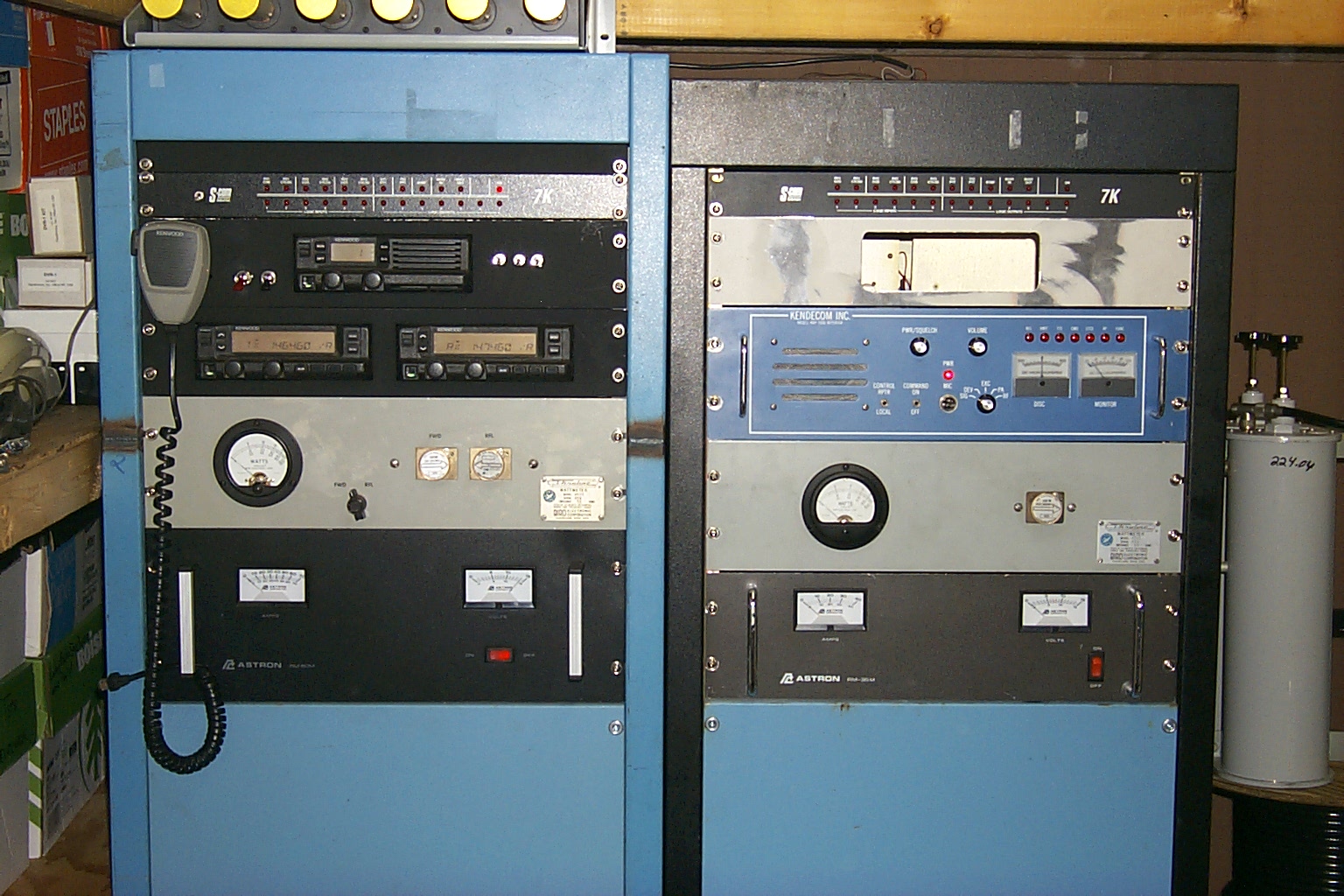
These photos show the 224.040 on the air, just sitting on a box in the repeater shed, next to the 146.460 / 447.775 / 927.6125 repeaters.
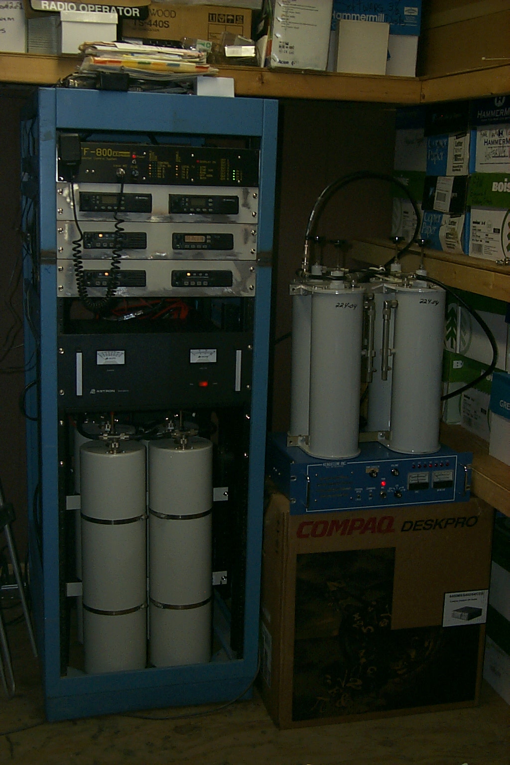
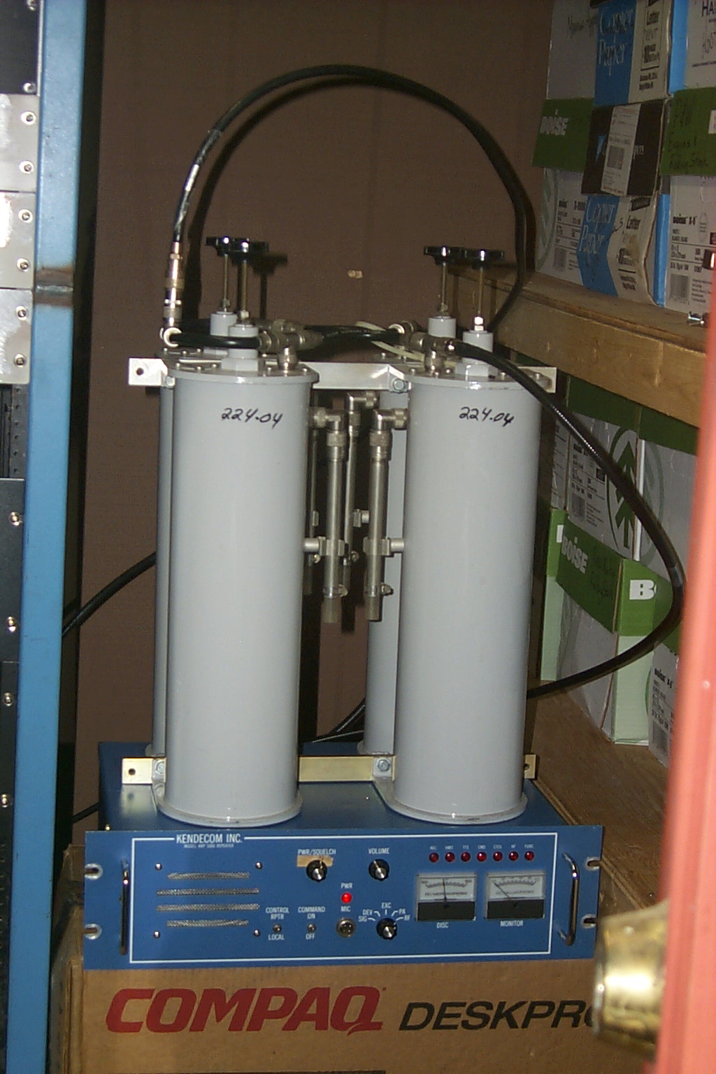
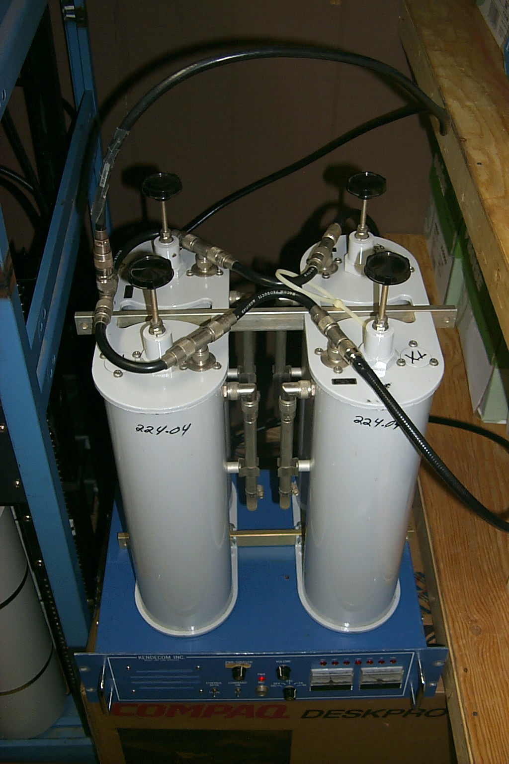
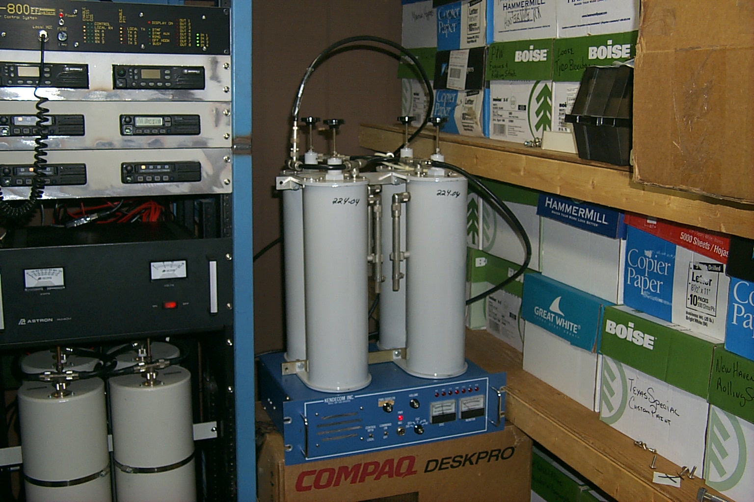
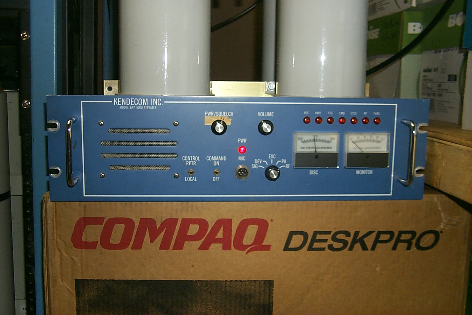
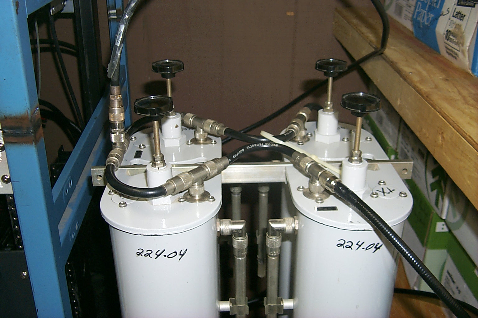
(click on images to enlarge)
Testing complete, let's fix it now even though nothing is broken.
After nine months of running the repeater in this configuration (everything worked as expected) I decided it was time for some upgrades, installing the hardware in a rack cabinet was one of my primary goals. When the repeater went into service I had been so busy rebuilding the Cumberland 146.940 repeater the 224.040 repeater, which was working fine, could be left on the back burner. Now that the new .94 repeater was back home in Cumberland I could pay some attending to the little 224.040 repeater.
I salvaged an old cabinet from a dumpster (better that going to a land fill) for the project and of course I had planned on making a new phasing harness for the duplexer out of Andrew FSJ-2 hard-line along with all new FSJ-2 interconnect cables. I had also purchased two additional Sinclair band pass cavities for some additional isolation and a Gas-FET preamp to improve the receivers sensitivity. So on Wednesday morning October 10th, 2007 at 5:00 AM in the morning I went out to the repeater site and collected all the components along with the empty cabinet, extra cavities, and a big pile of hard-line and connectors.
Round One... Let the screaming begin.
At this point I should explain that October 10th is my wedding anniversary. Nothing say's "I Love You" like getting up at 5:00 AM in the morning and dragging a big pile of repeater hardware into your house on your wedding anniversary. My wife Sandy KA1RXB is truly a saint when it comes to my sick obsession with repeaters, once we got past all the screaming at 7:00 AM when Sandy got up and found the 224.040 repeater scattered in pieces all over the house, I got to work putting together this latest repeater project.
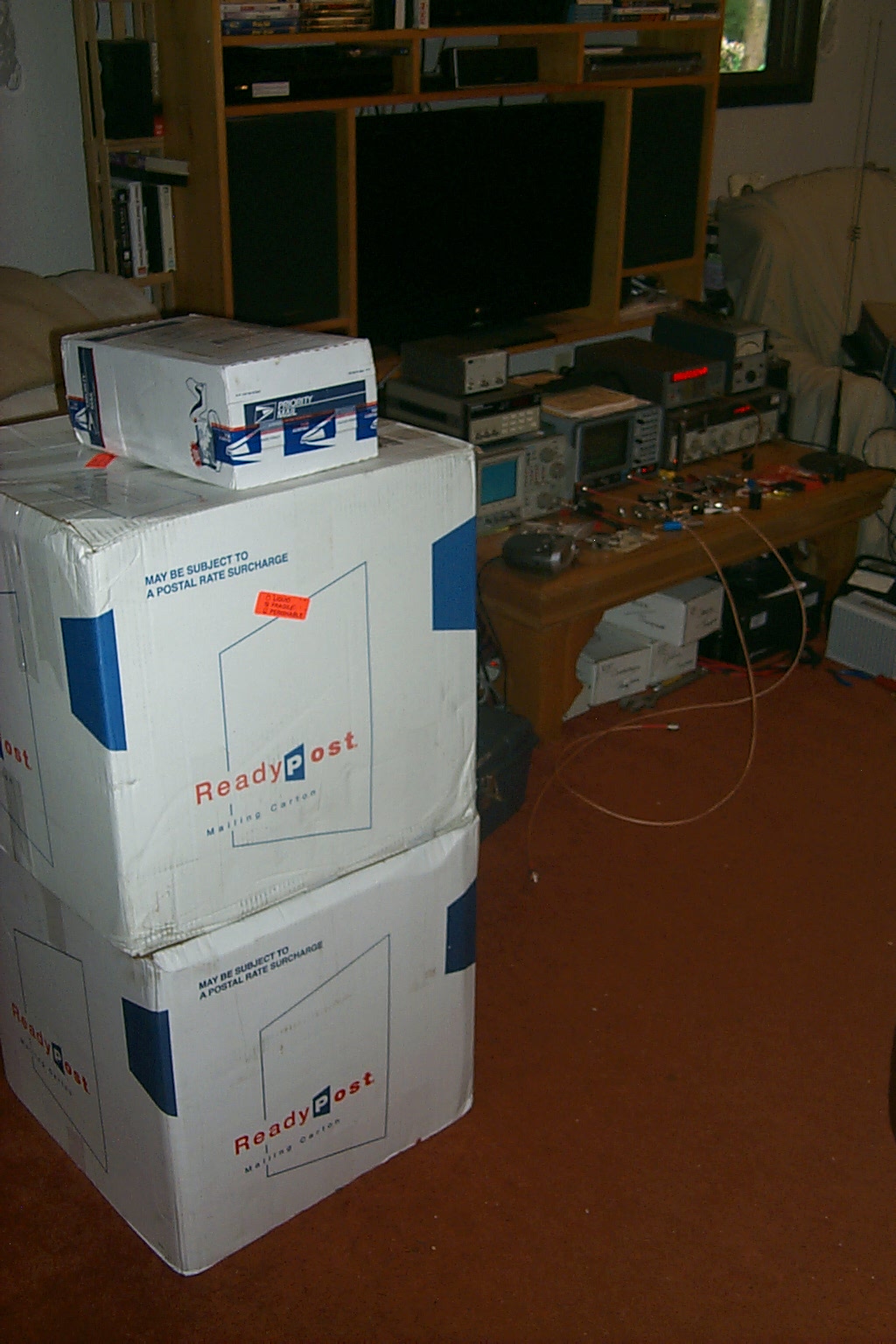
These photos were taken early in the morning as I assembled all the parts for the project. You can see the empty 46 inch rack cabinet before the build, the extra band-pass cavities, and the existing repeater hardware now all back at the house for the rebuild / upgrade.
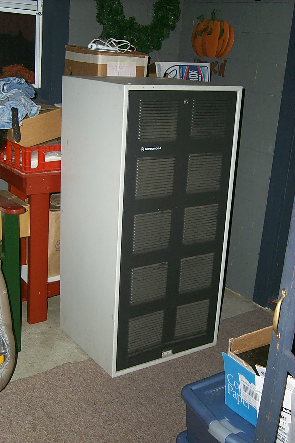
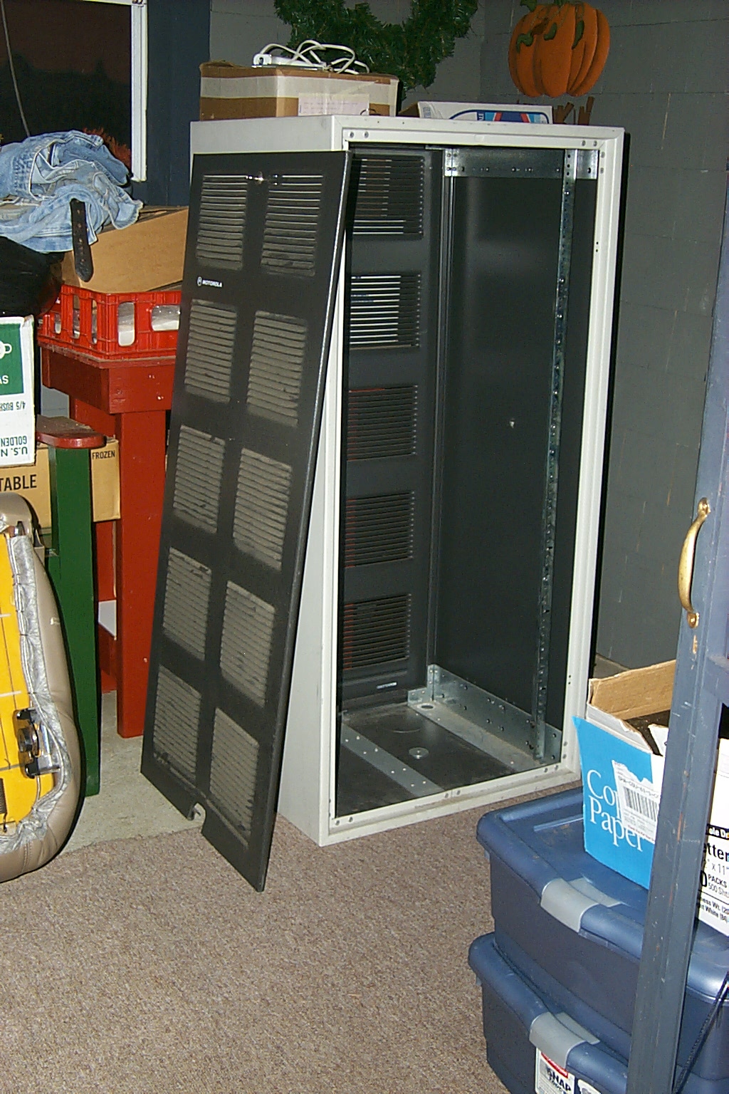
(click on images to enlarge)
When I started to mock up all the hardware in the cabinet it became clear that there would not be enough room in the 46 inch cabinet for all the new hardware that I wanted to add. I was going to upgrade to a S-Com 7K controller and add a Kenwood TK-830 link radio so the 224.040 repeater could be linked into the KA1RCI network full time.
With the existing duplexer and additional band-pass cavities I would be THREE INCHES short on rack space. I tried several different configurations for the hardware but it just will not fit in this cabinet. Denis KD1HA donated two small 30 inch cabinets that could be bolted together but the cavities will not fit properly in the 30 inch space either so now the repeater was in pieces all over the house while I search high and low for a 60 inch cabinet.
224.040 Version 2.0b (beta)
It was killing me having the 224.040 repeater off the air with no idea when I would be able to find an appropriate rack cabinet suitable for this project. I decided to cobbled together new a temporary configuration while adding in the extra band-pass cavities and 20 dB GasFET preamp using one of the small 30 inch cabinets. This would just be a stop gap measure to get the repeater back on the air with hopefully more isolation and improved receiver sensitivity.
These photos show the quickly assembled (beta) configuration pulled together at 10:00 pm on October 10th, 2007

(click on images to enlarge)
My brother-in-law Keith helped me drag all the hardware back to the repeater site and we had 224.040 back on the air by 10:30 pm that night. There was only one problem, I could not find anyone around to help with signal testing, so we headed back home in "wait and see" mode. Later that night, just after 12:00 AM (midnight) now actually October 11th, I was able to connect with Scott N1RWW and he did some testing with my on 224.040 from his QTH. Scott could not raise the repeater, he reported that he could hear the signal, however the repeater was not hearing him at all...
Disappointment turns into revelation and 224.040 V2.01b (second beta)
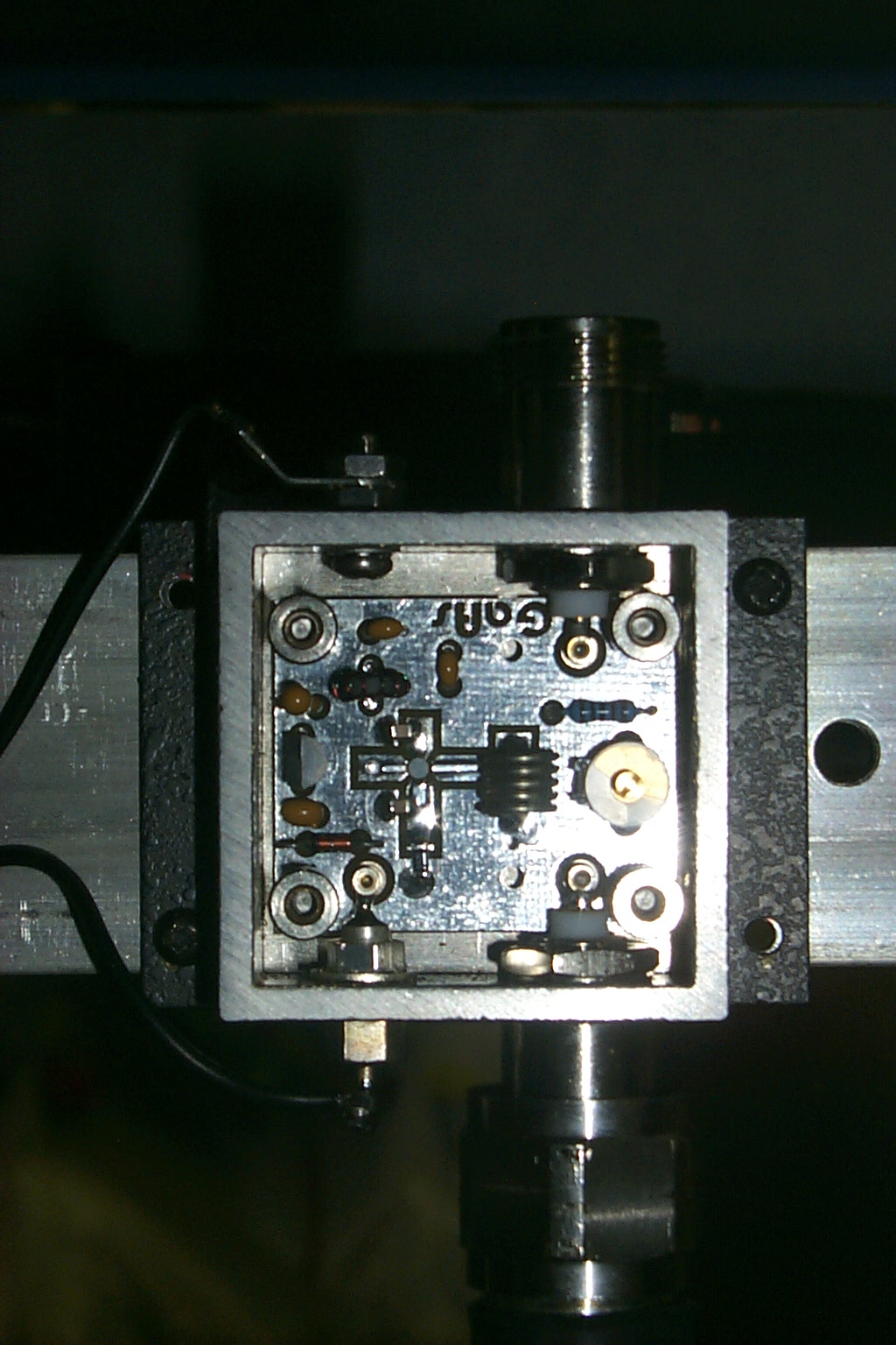
Now back at the site, at 1:00 AM in the morning, I was staring that the assembled pile of parts when I suddenly noticed the printing on the preamp. In my haste to cobble together the new hardware in this temporary configuration I had over looked the tiny little (in) and (out) printing on the GastFET pre-amplifier. I have found that these actually work MUCH better when you do not install them backwards!
After carefully correcting my stupid mistake I headed back home for some much needed sleep. My head hit the pillow about 2:45 AM in the morning but I really did not sleep all that well with one eye peeking at the clock while clutching my little Kenwood TH-F6 handheld.
I just needed someone to check into the repeater to see if everything was working.
These photos show the now corrected 224.040 V2.01b deployed at the repeater site
(click on images to enlarge)
Finally someone check's in!
Sometime after 7:00 AM in the morning Lee N3LEE checked into the 224.040 repeater from his mobile somewhere in Woonsocket and carried the repeater all the way down route 146 south thru Lincoln, No Providence, Providence while on his way to Warwick. He was able to carry the repeater to route 37 which confirmed to me that it was working as well or better than before.
The search for a bigger cabinet continues...
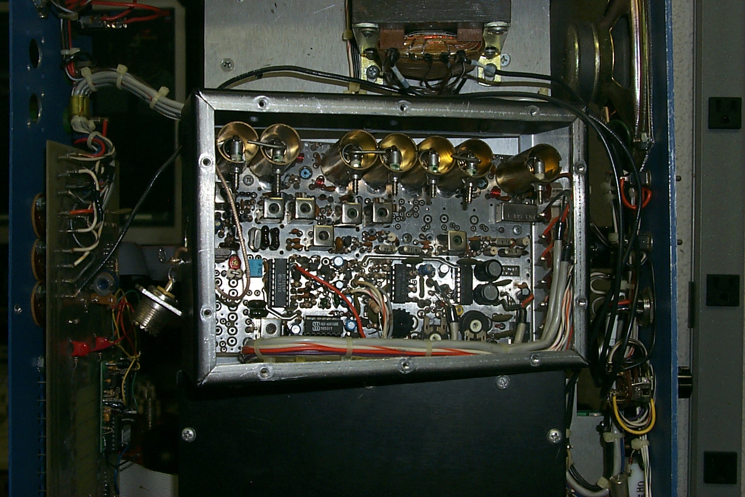
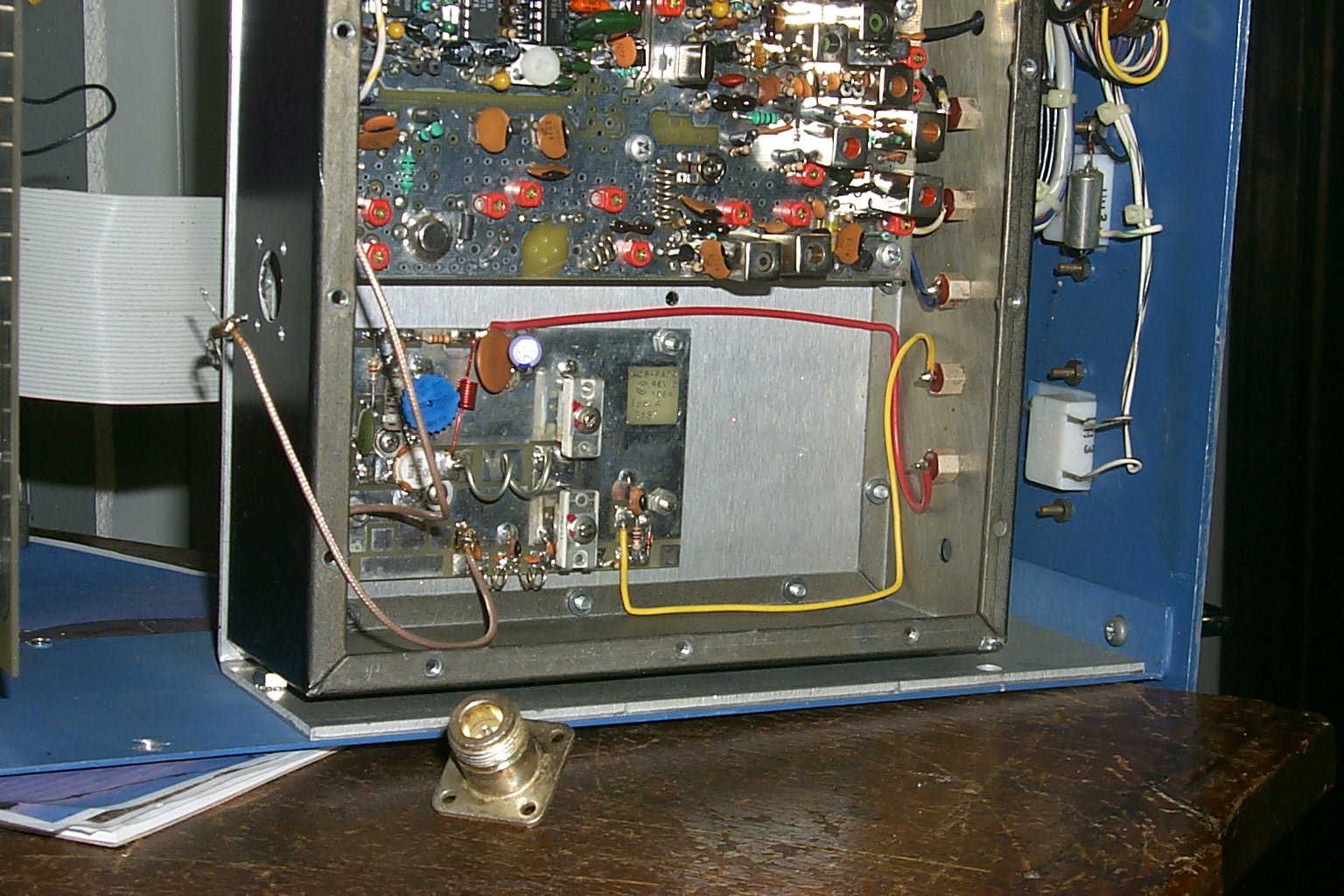
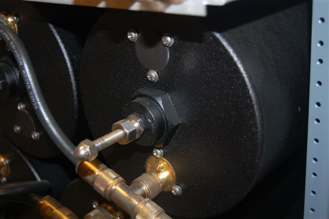
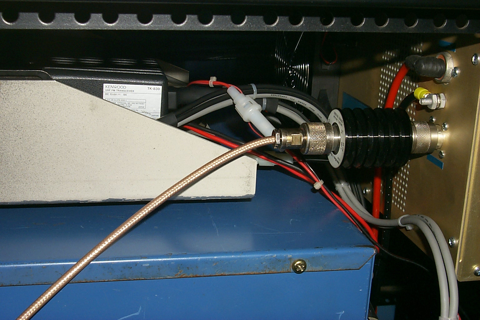
While I was trying to find a bigger rack cabinet to mount all this hardware in I started to rebuild the repeaters RF connections. The Kendecom hardware has several SO-239 and PL-259 connectors and I wanted to eliminate all of these unnecessary connections and put one Type-N bulk head connector in the receiver and transmitter that will connect directly to the duplexer.
(click on images to enlarge)
I also started build the new TK-830 UHF link radio and S-Com 7K controller so the 224.040 repeater could be linked into the network.

(click on images to enlarge)
Update November 15th 2007
Still searching for an appropriate rack cabinet to mount all this hardware in.
The new power amplifier arrived in the early afternoon on Nov 15th and I was eager to get it installed however I still have not found an appropriate rack cabinet to mount all the hardware in so the repeater is still just a loose collection of parts sitting on boxes in the repeater shed so I am not sure if I will even be able to find a "box" to sit the new PA on.
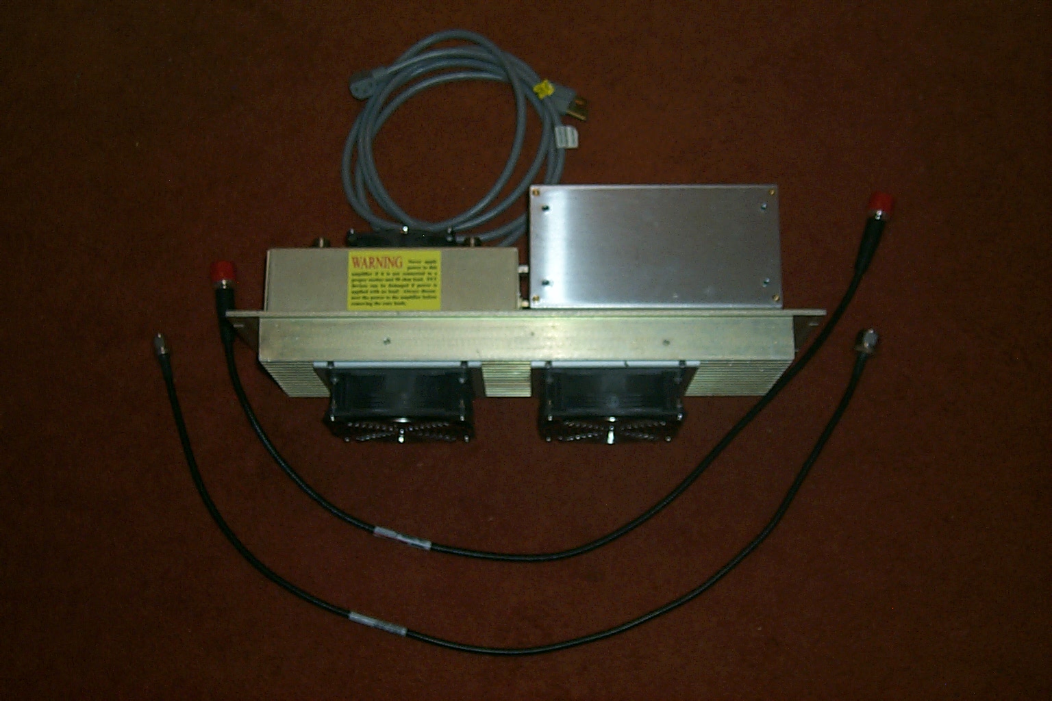
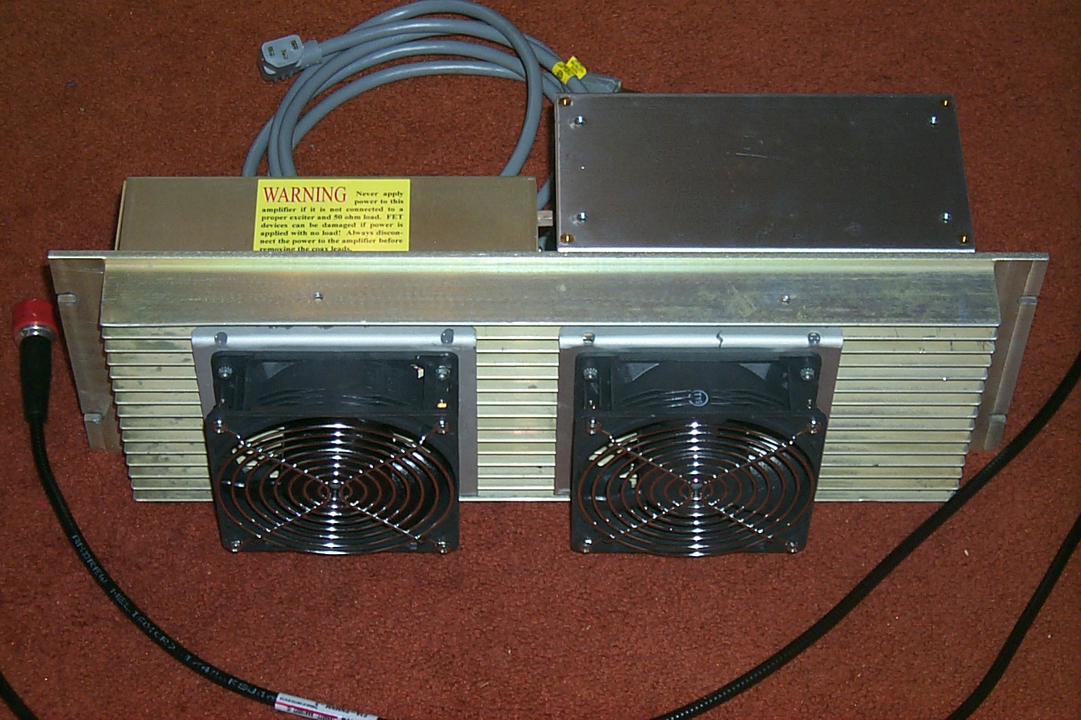
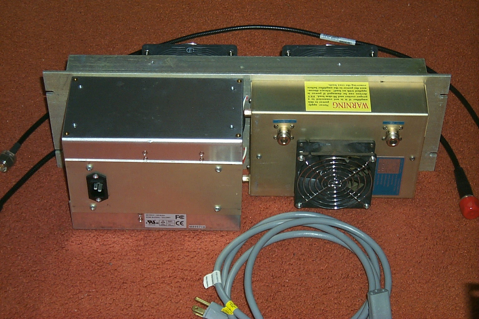
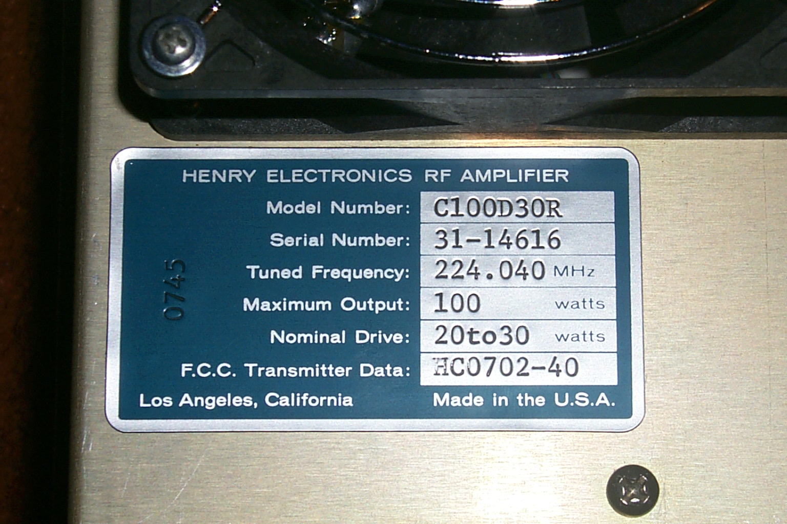
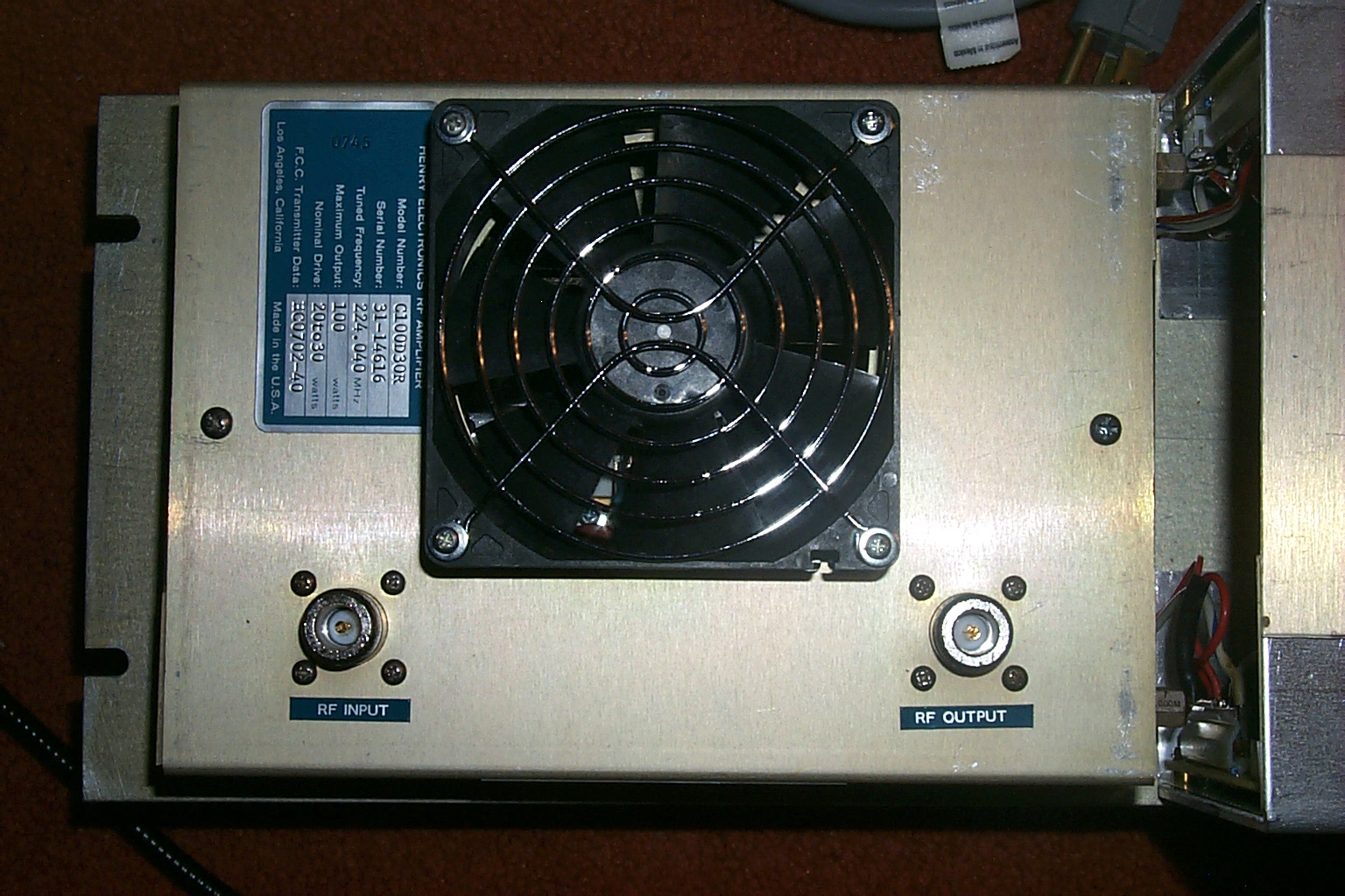
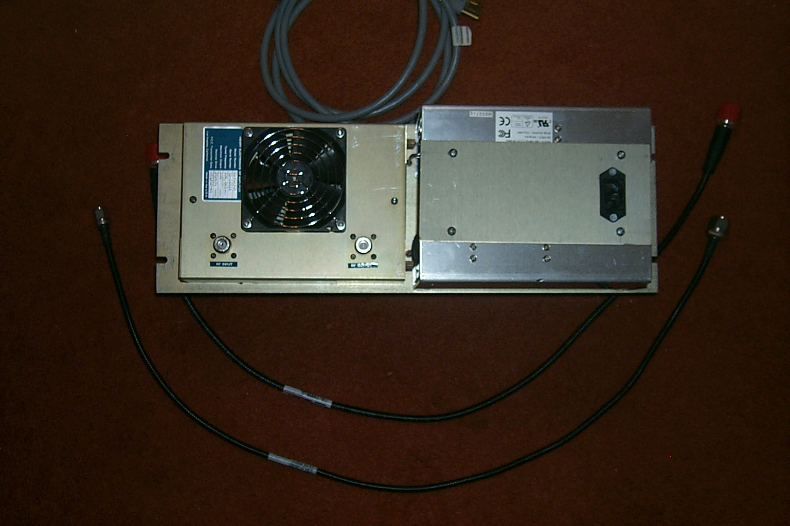
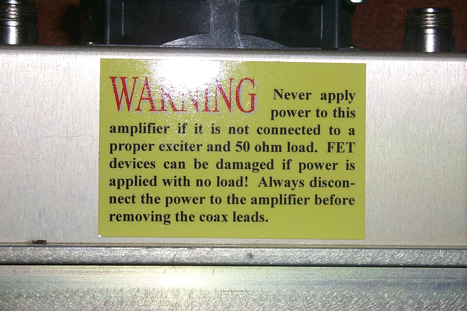
(click on images to enlarge)
I was able to get out to the repeater site after dinner and after some testing put the new PA online. Everything is just stacked up on cardboard boxes but it is on the air...
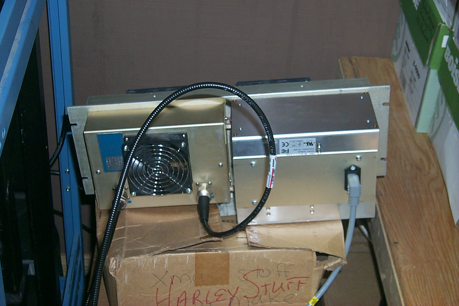
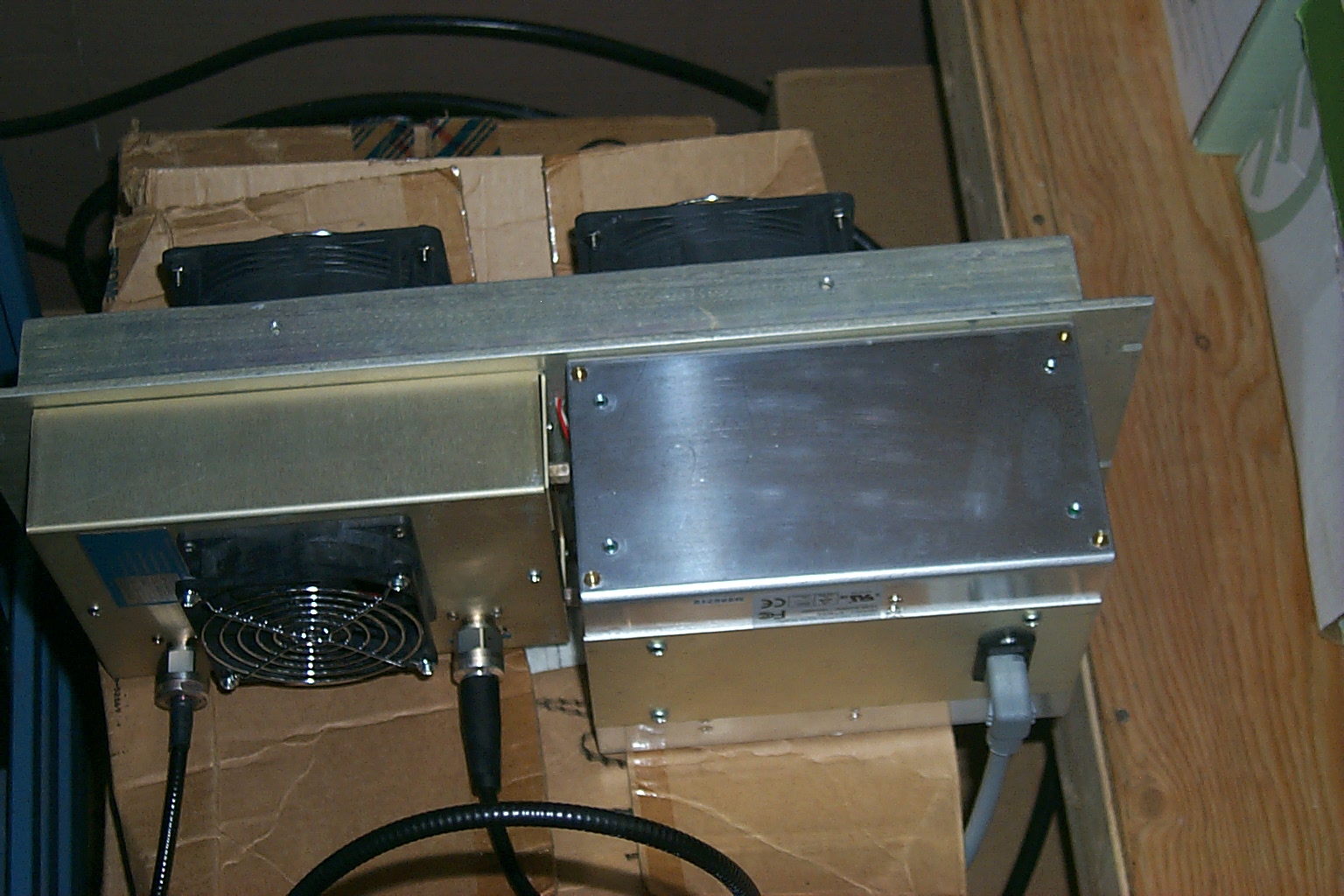
(click on images to enlarge)
Update - New Rack Cabinets
224.040 Version 3.01b (beta)
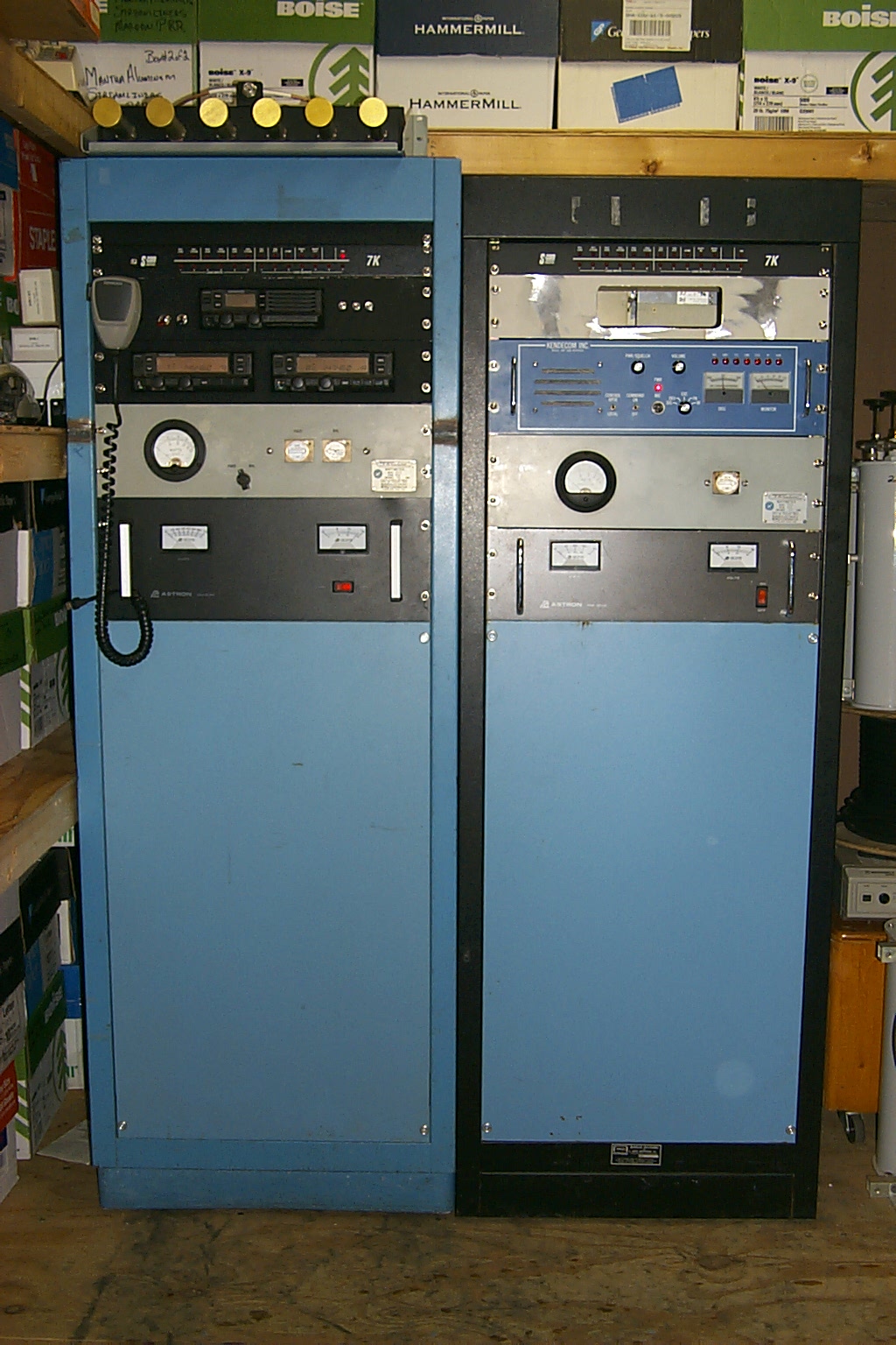
I was able to find two more cabinets very similar to the original rack that my brother-in-law Scott had cut down to fit in the repeater vault. These two new cabinets would allow me to rebuild the Lincoln repeaters into individual racks each with their own controller making repairs and maintenance much easier.
These two photos show the three racks lined up in the house as I started rebuilding all the hardware. Syl N1DKF help getting the cabinets ready tracking down wheels and other specialty hardware for the racks.
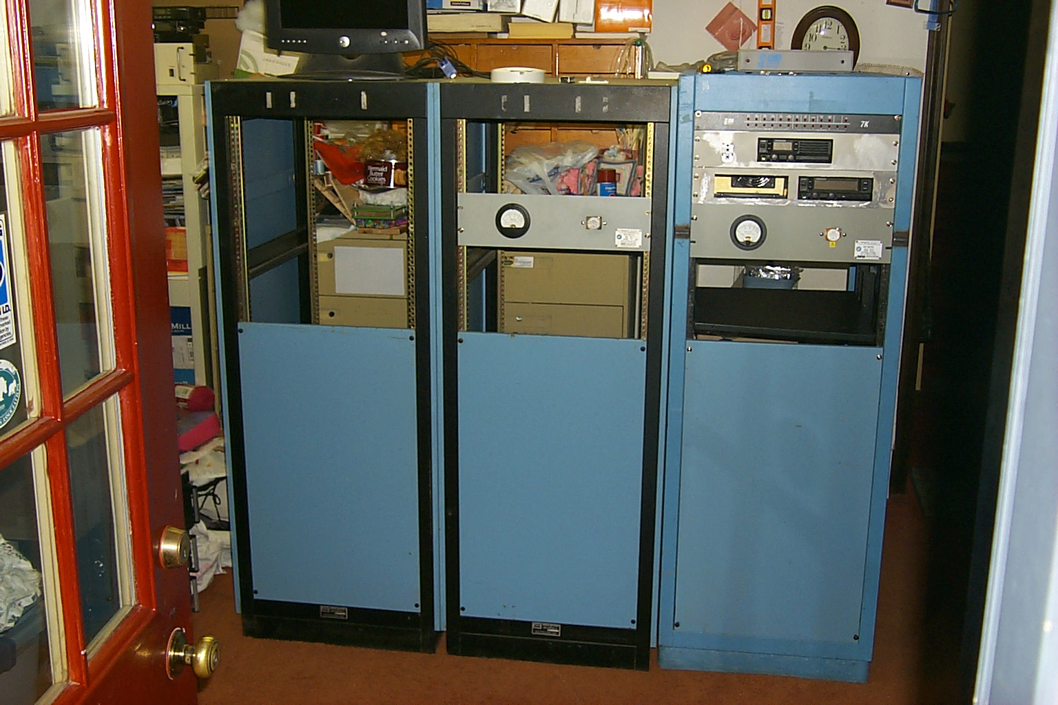
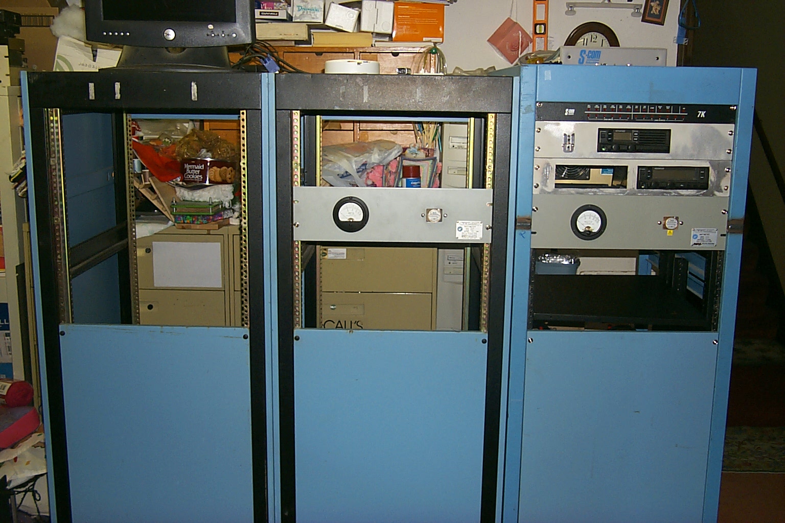
(click on images to enlarge)
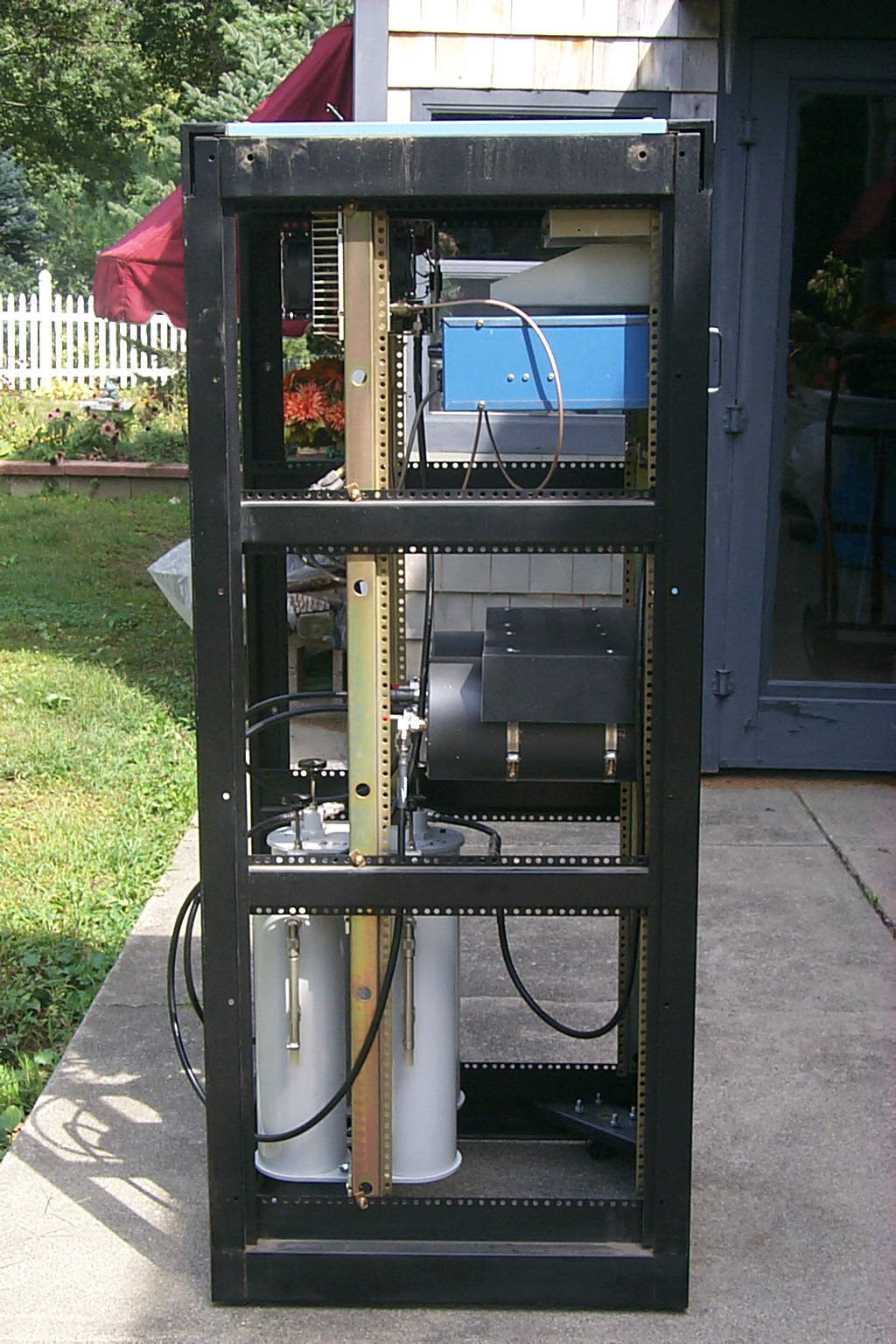
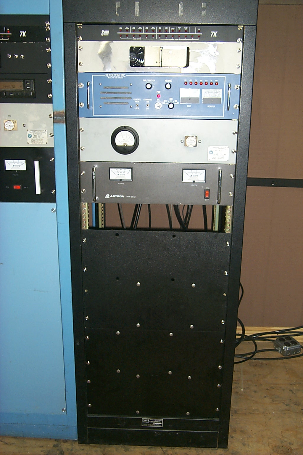
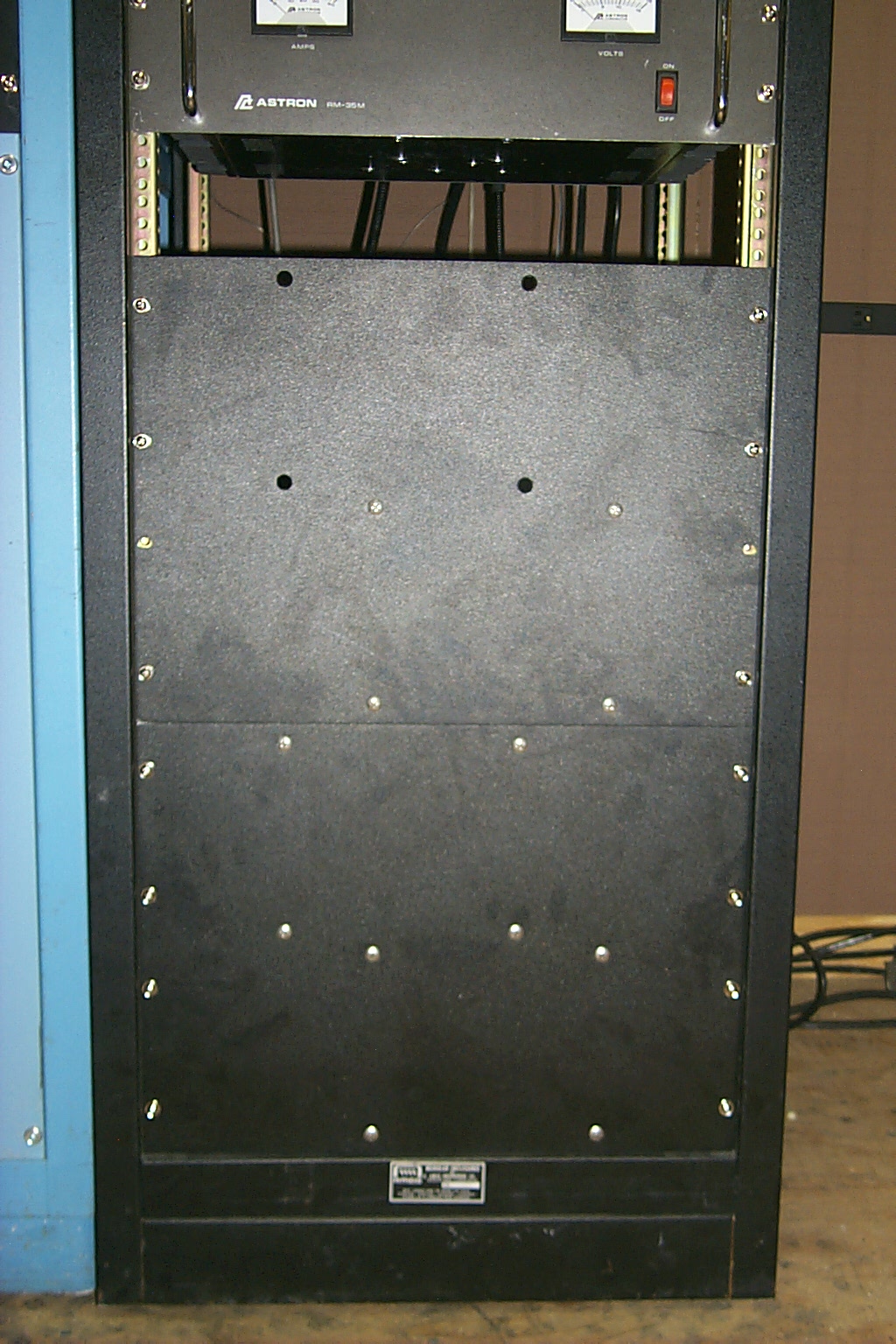
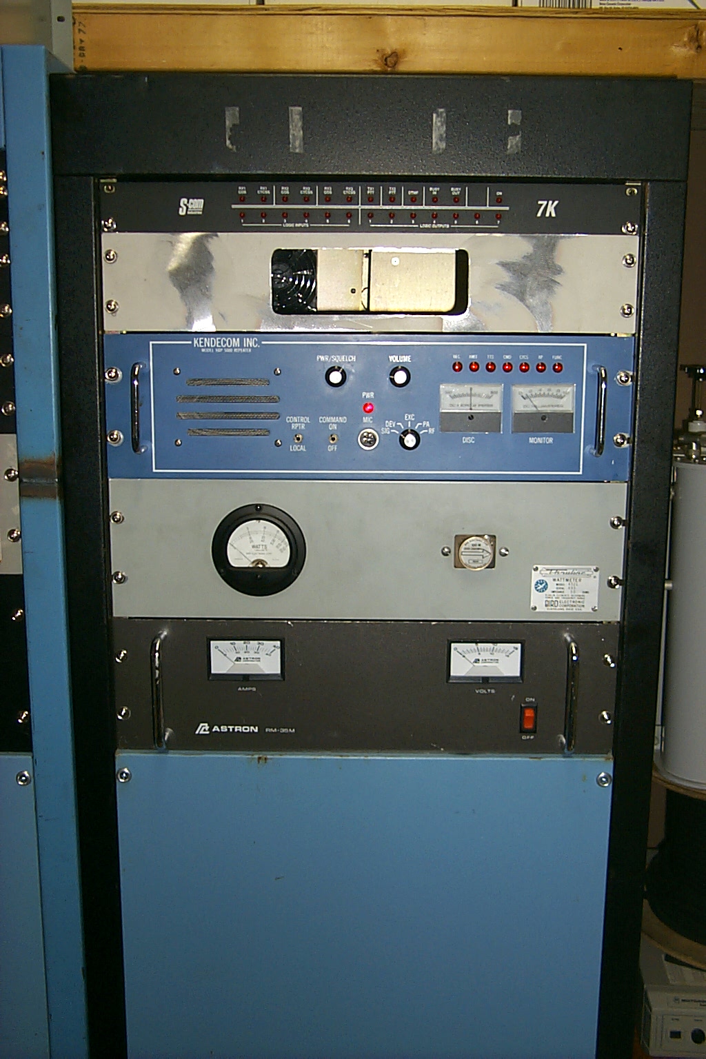
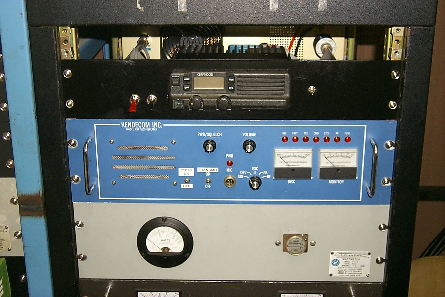
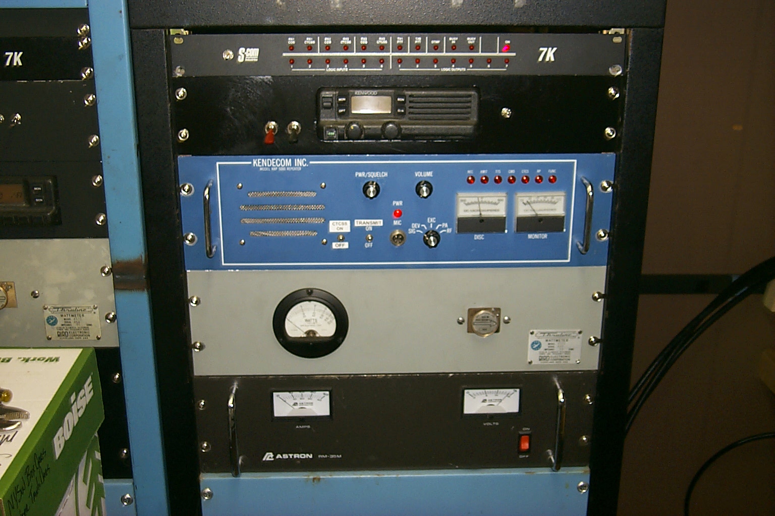
After I finished rebuilding the 146.460 repeater in the original rack cabinet I dragged all the loose 224.040 hardware that had been haphazardly scattered about the repeater vault sitting on boxes etc. down to the radio room and started building out the hardware in one of the new rack cabinets.
Starting about 8:00 am in the morning taking apart the collection of loose hardware stacked up on boxes I spend the better part of 16 hours mounting all the hardware into one of the new rack cabinets. I have had to fabricate brackets, send Sandy to her brother's house to have some custom metal work done, on and on.

(click on images to enlarge)
(click on images to enlarge)
My guess is the repeaters receiver performance will be very good again when I move everything back to the shed.
(click on images to enlarge)
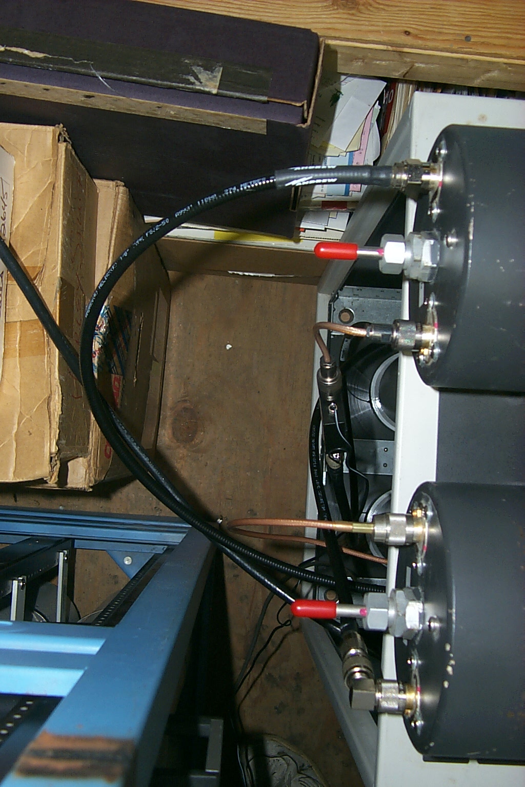
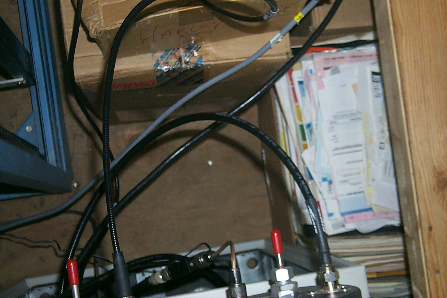
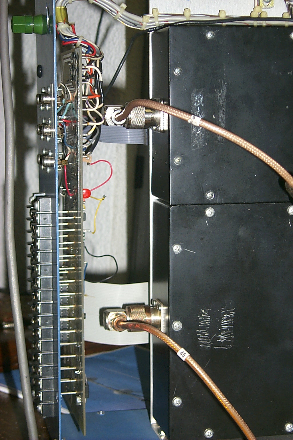
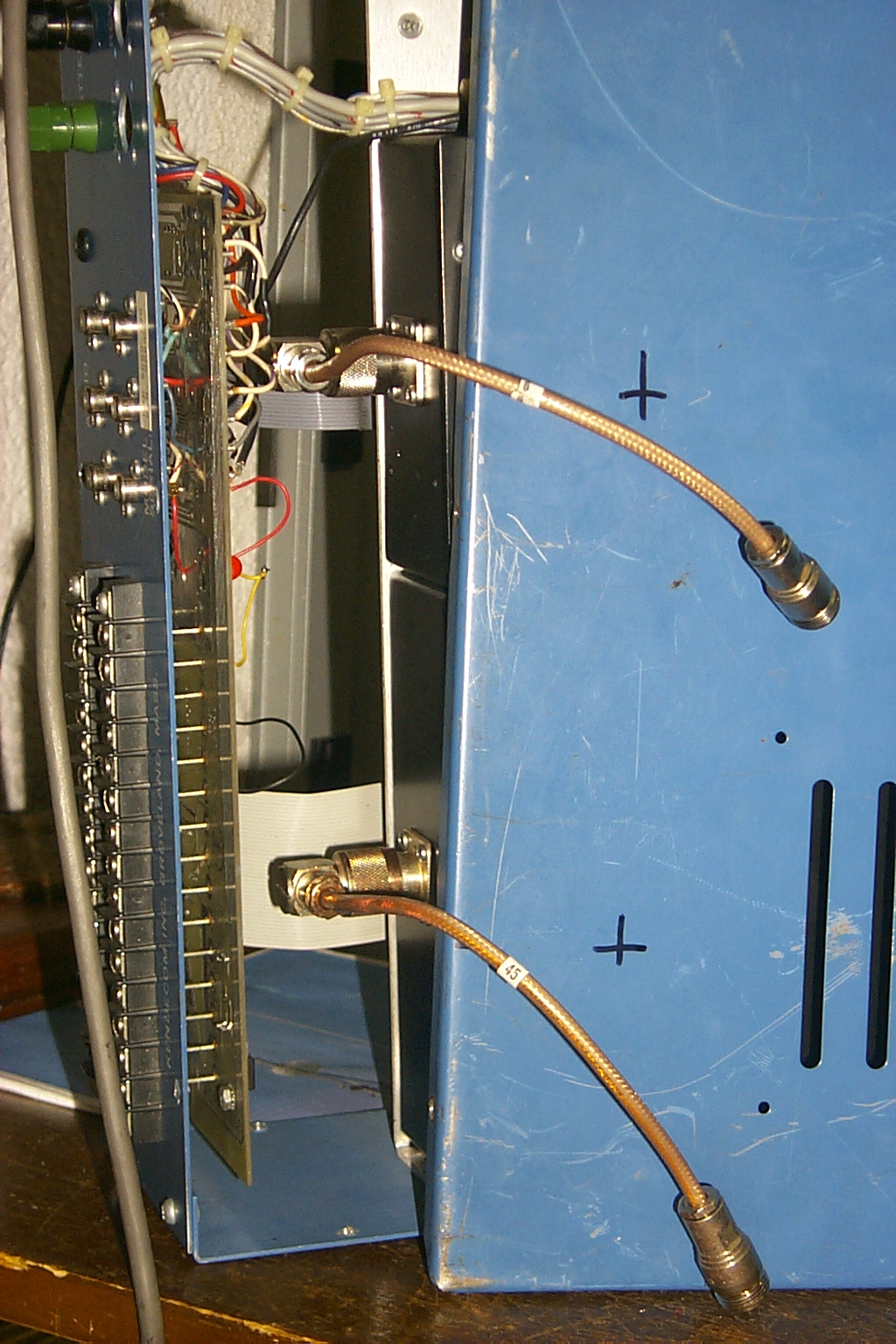
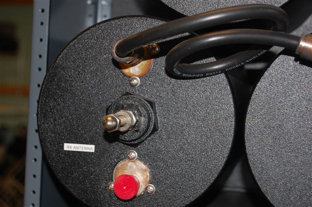
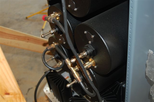
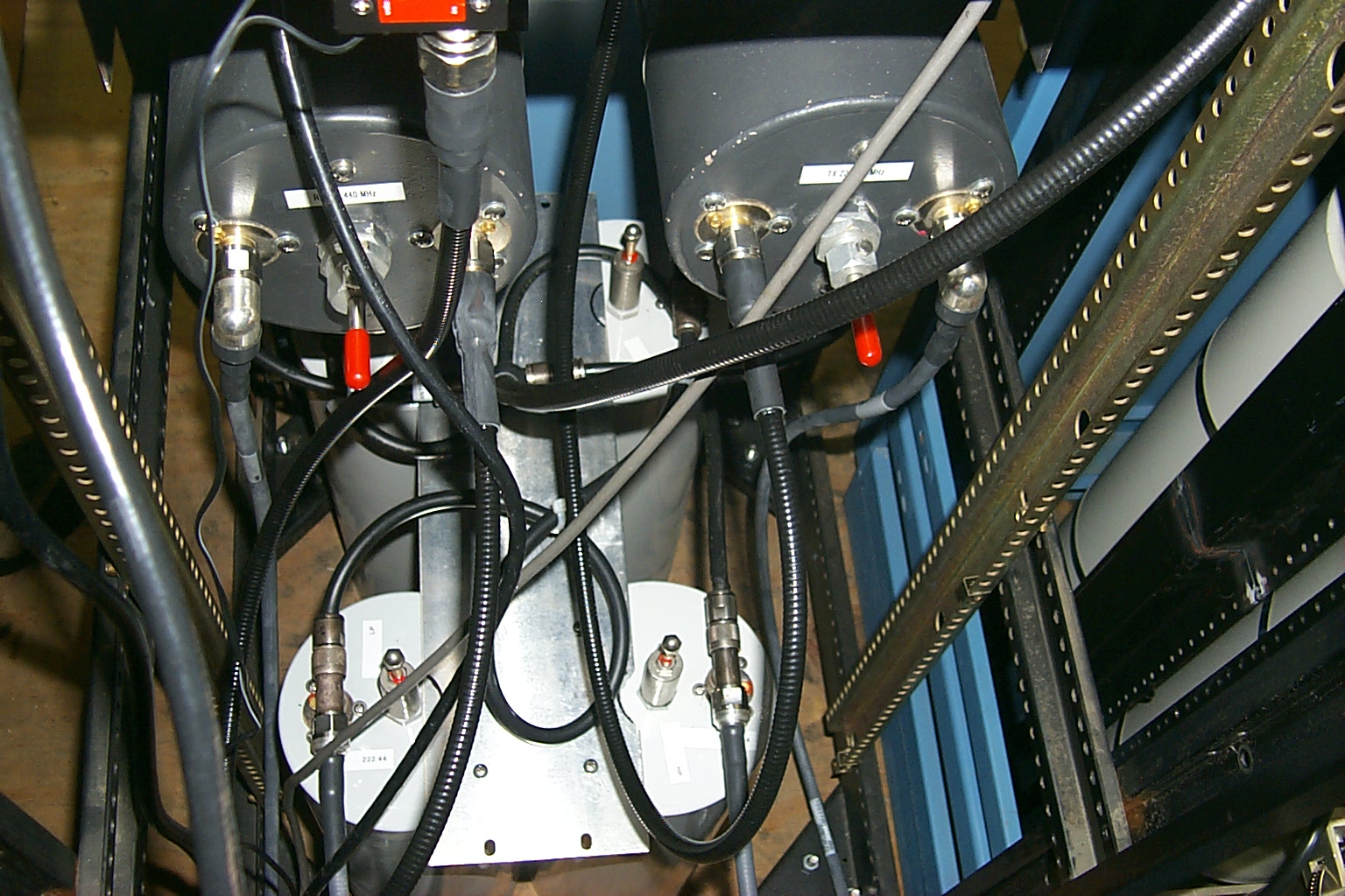
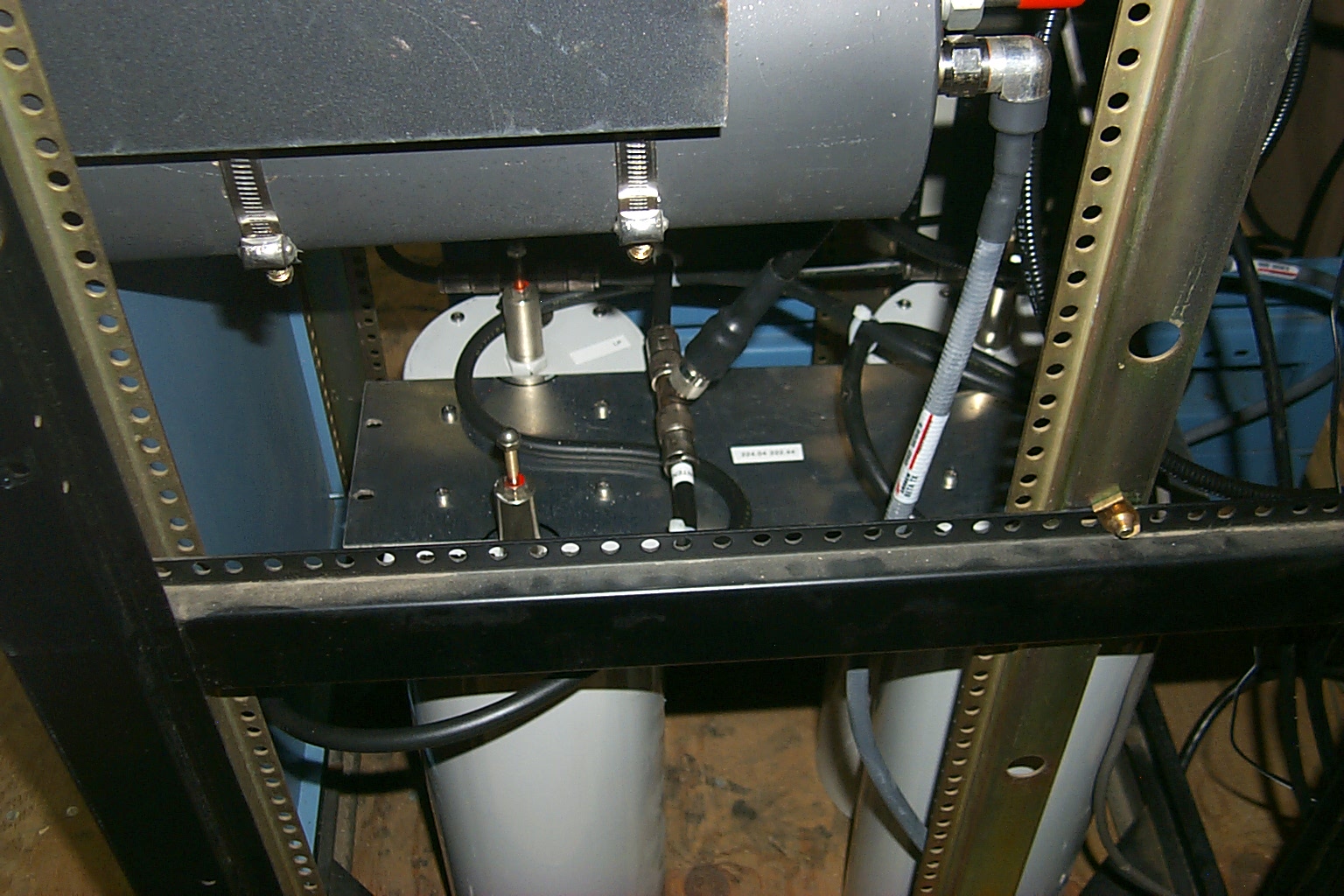
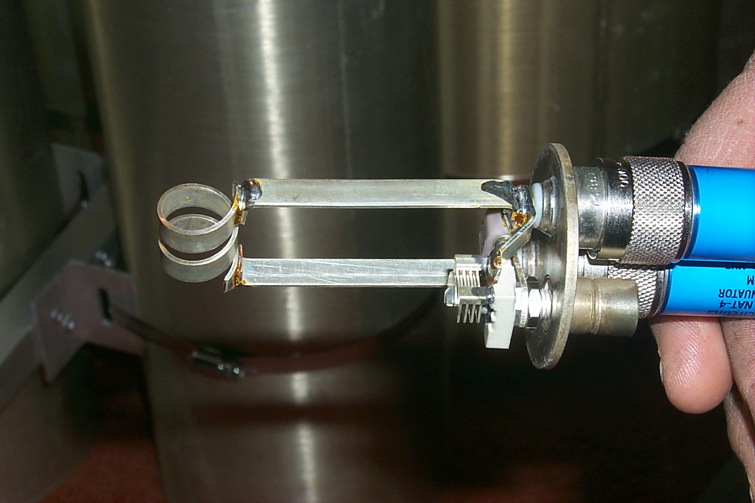
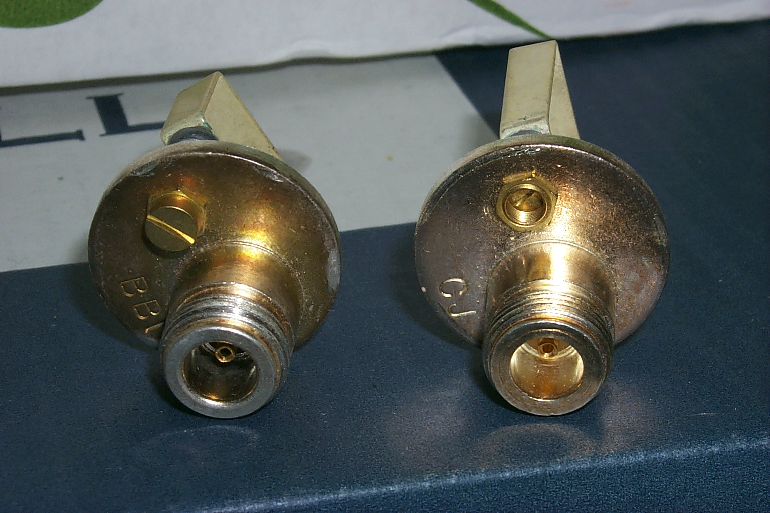
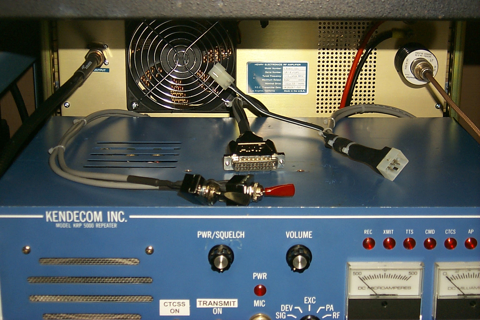
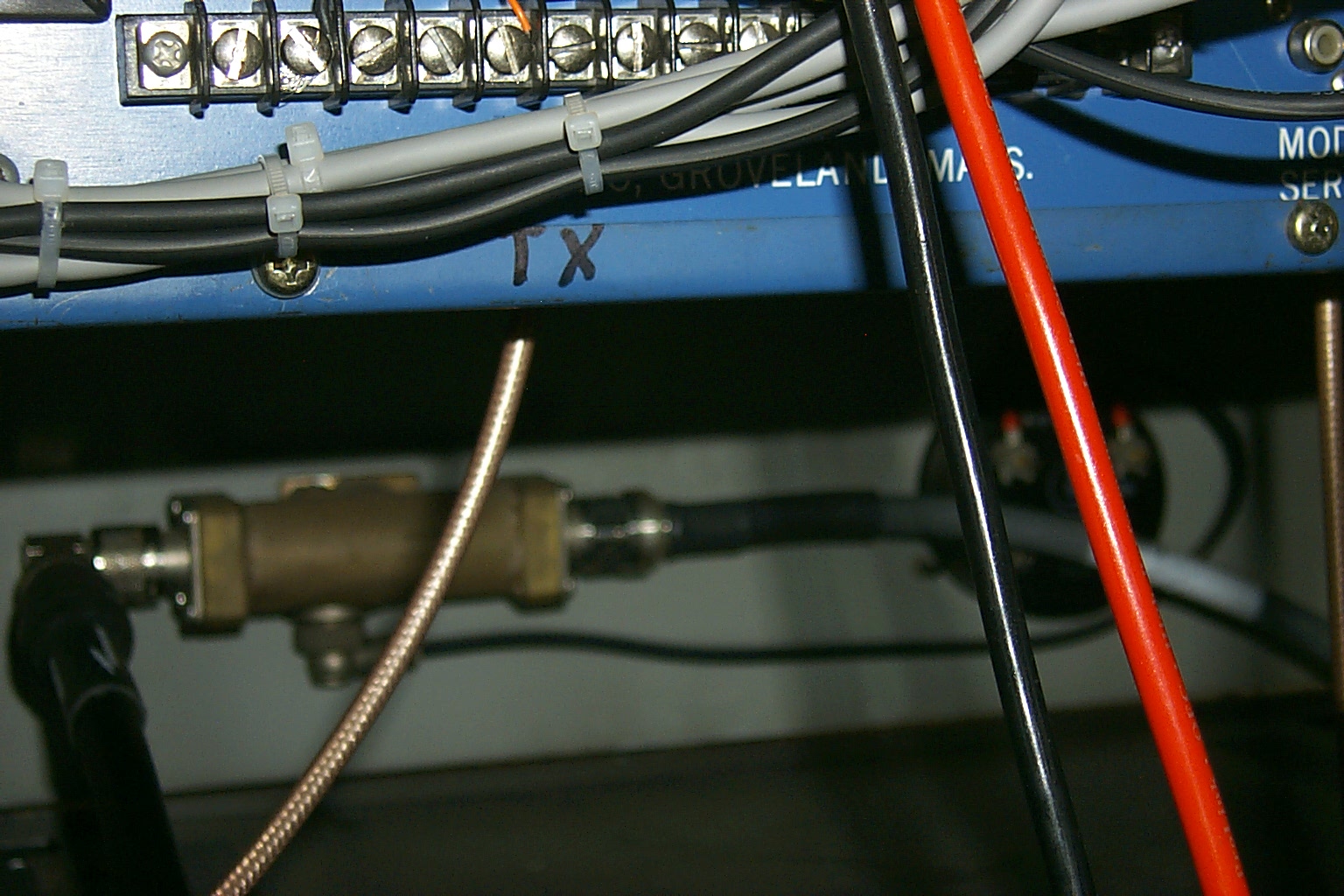
Replacing the old SO-239 and PL-259 connectors
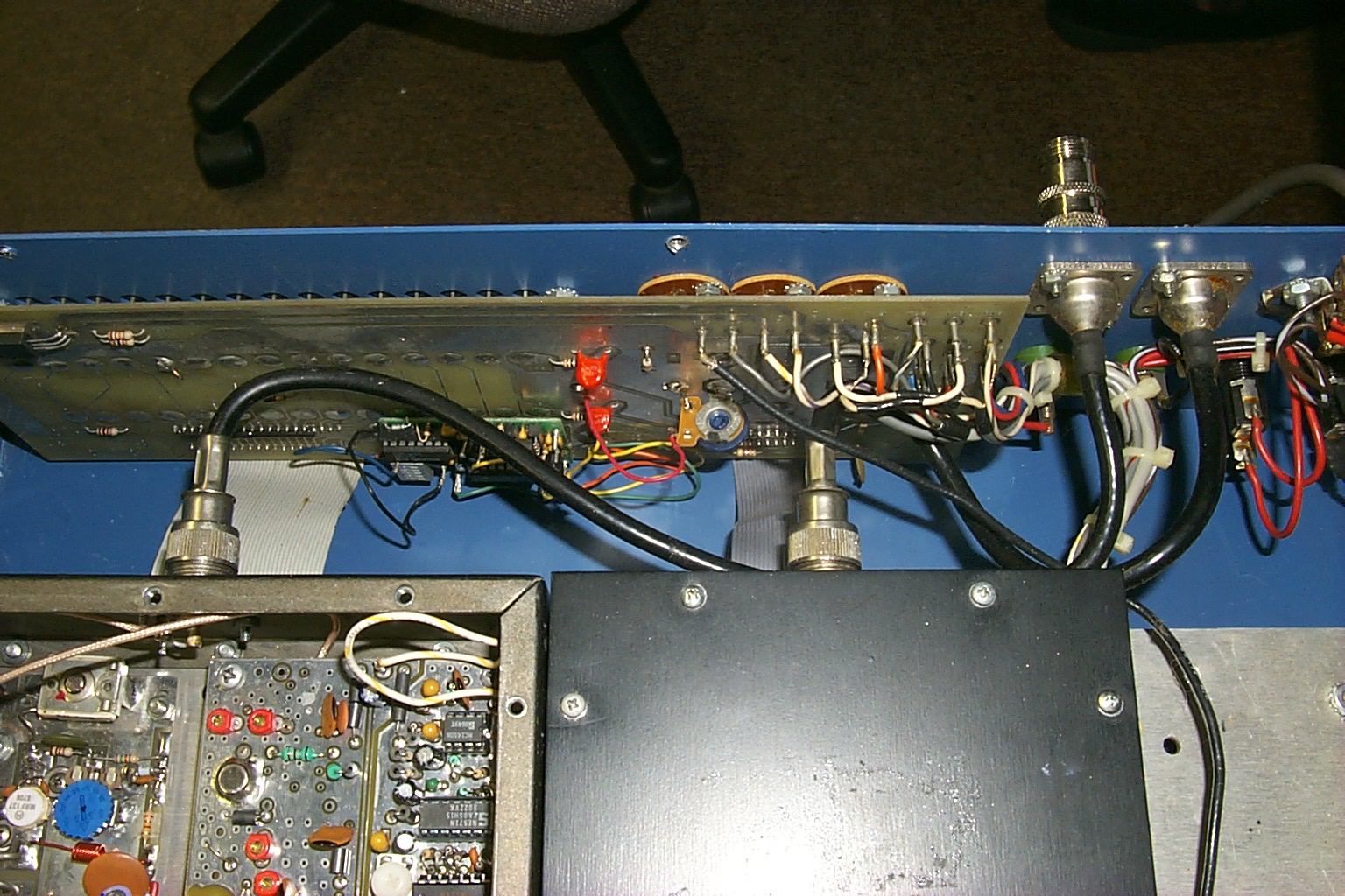
Ever since that very first day that I unpacked the repeater and put it on the air I was bothered by the old 8-X feed-line with the SO-239 bulk head fittings and PL-259 connectors. Both the transmitter and receiver had SO-239 bulk head fittings, then there was a short run of 8-X style feed-line with CRIMPED PL-259 connectors that connected to two more SO-239 bulk head fittings.
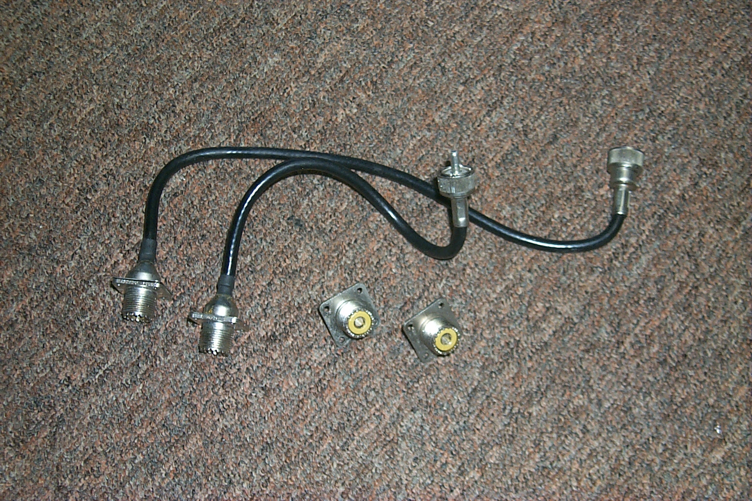
(click on images to enlarge)
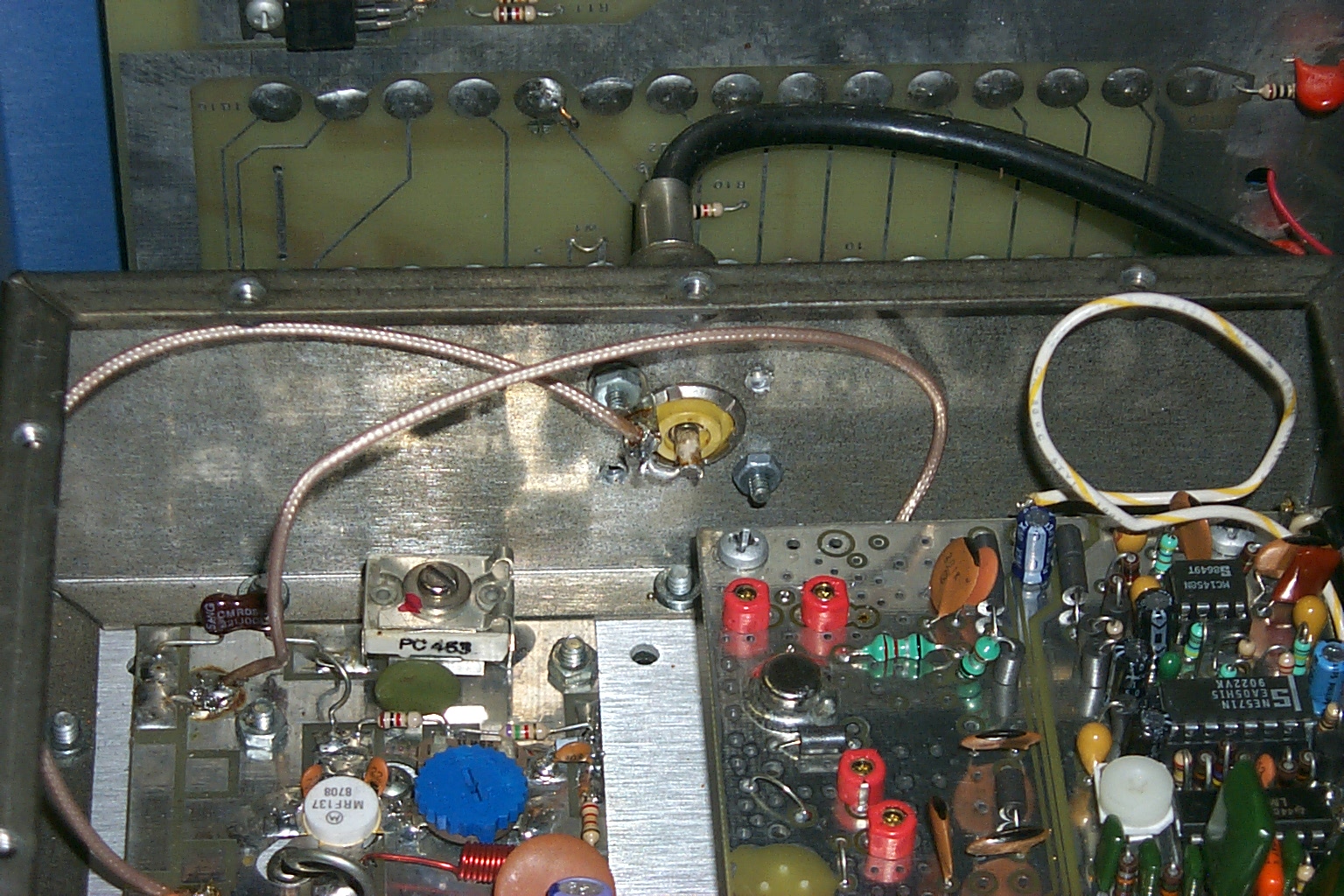
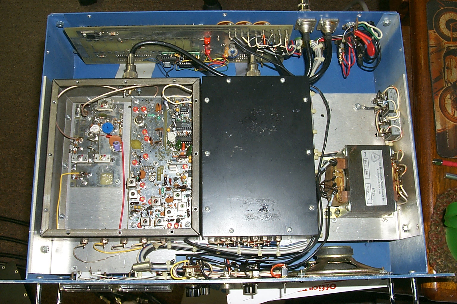
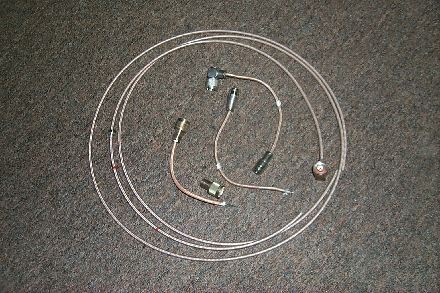
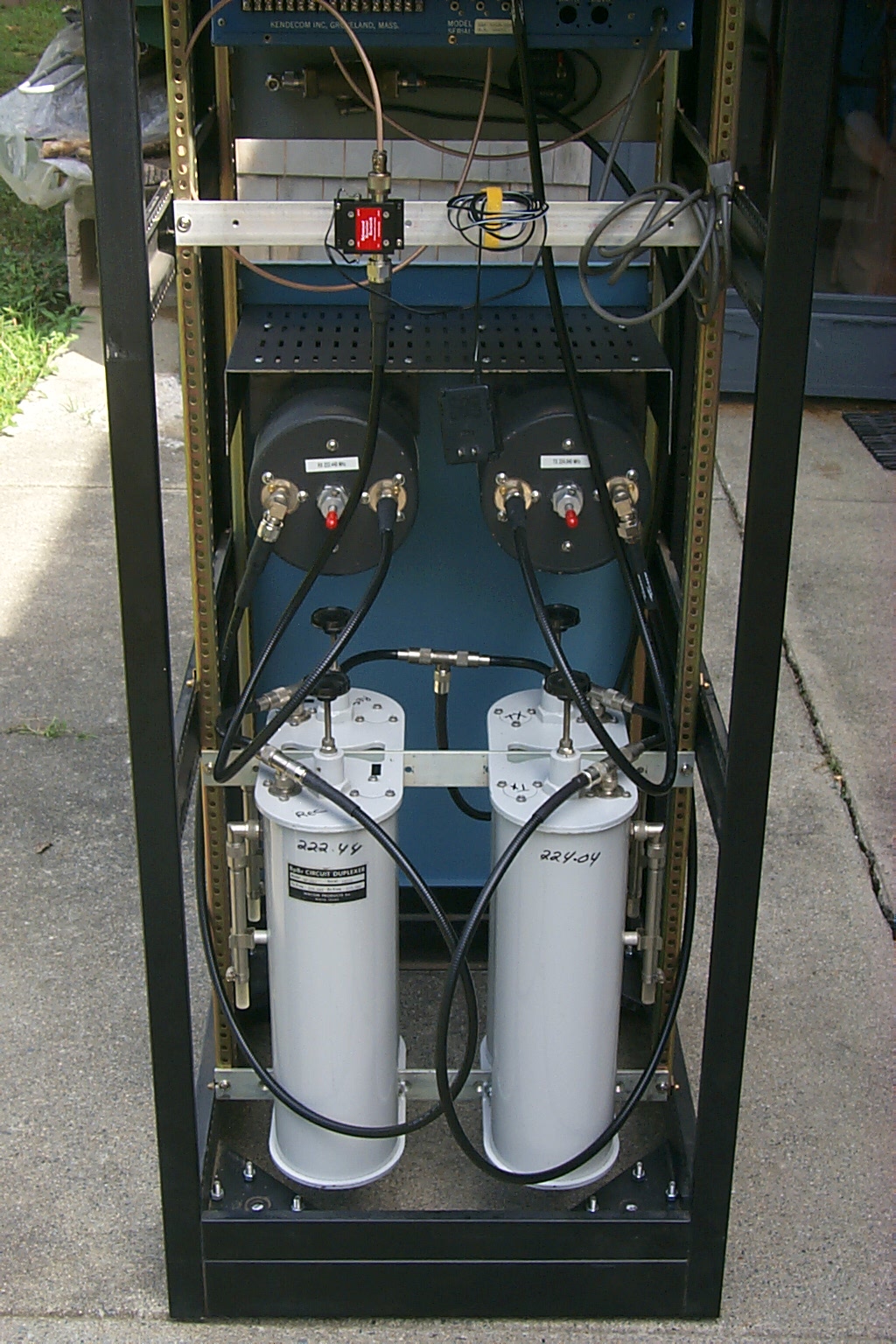
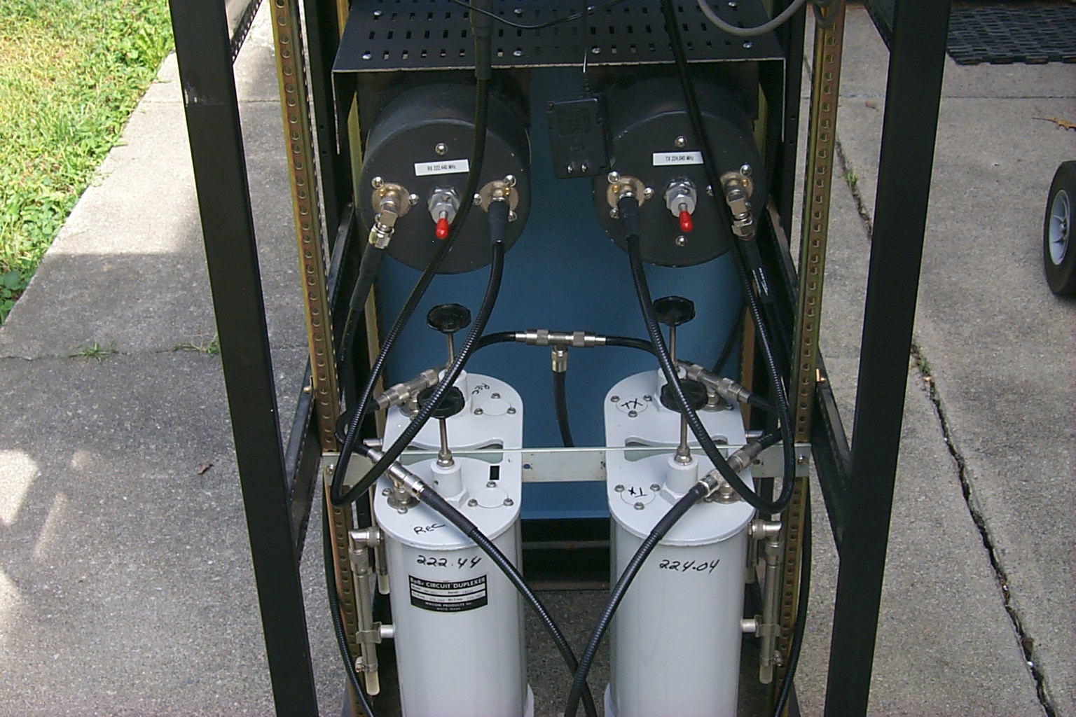
I ripped all of that out replacing the transmitter and receiver SO-239 fittings with Type-N bulk head fittings. Then I made custom RG-142 double shielded cables that would connect directly from the transmitter to the PA and from the receiver to the preamp eliminating all of those SO-239 / PL-259 connections.
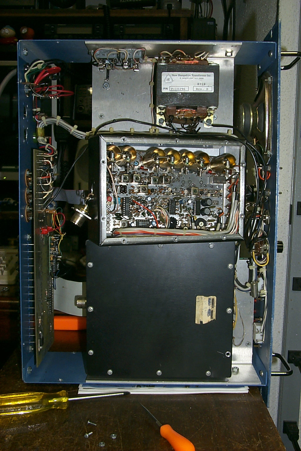
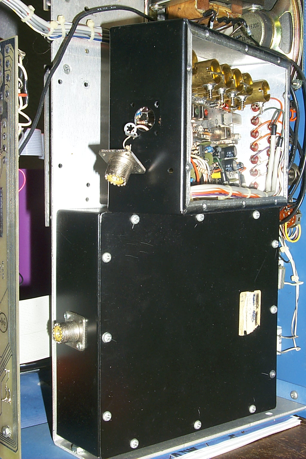
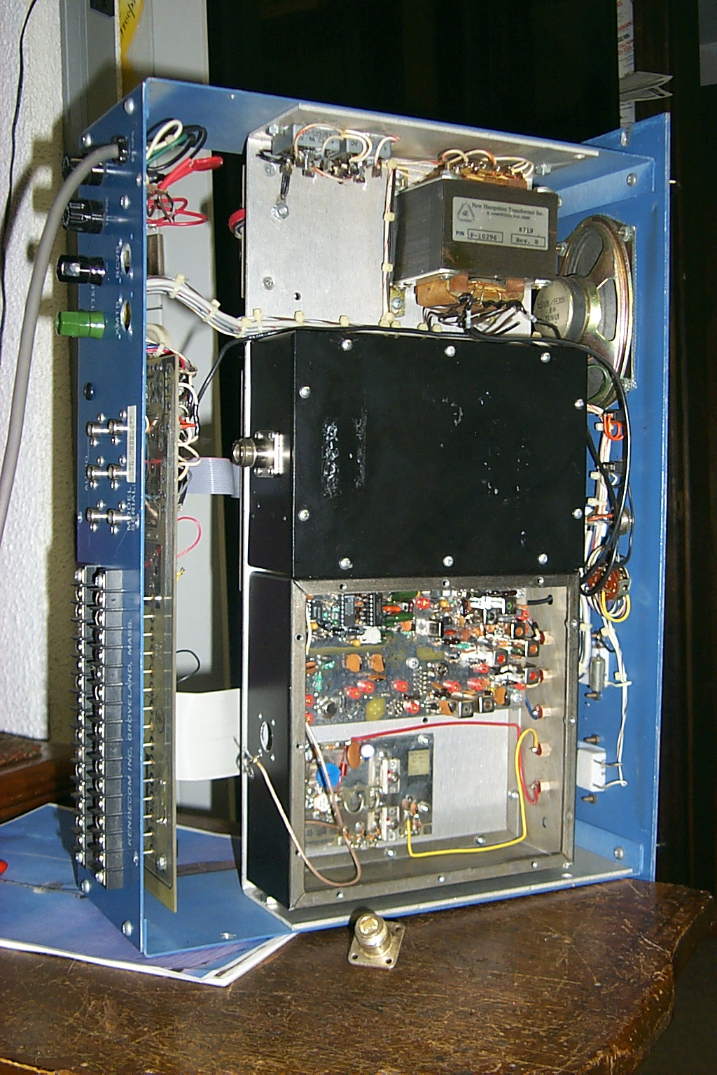
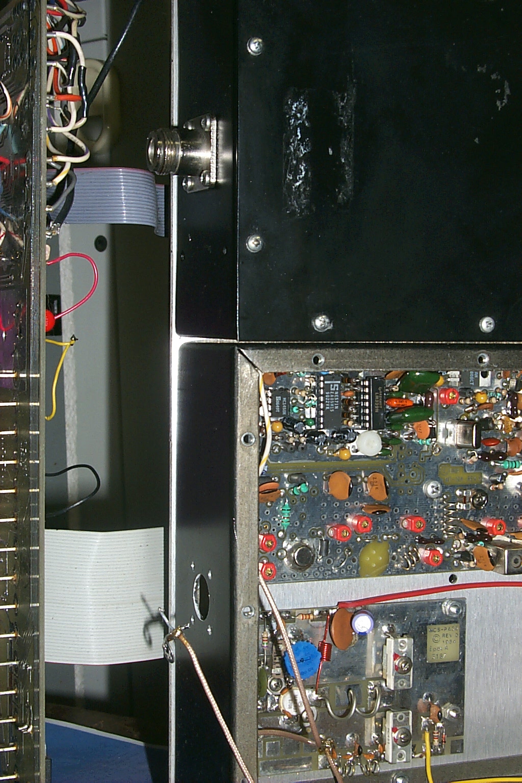
(click on images to enlarge)
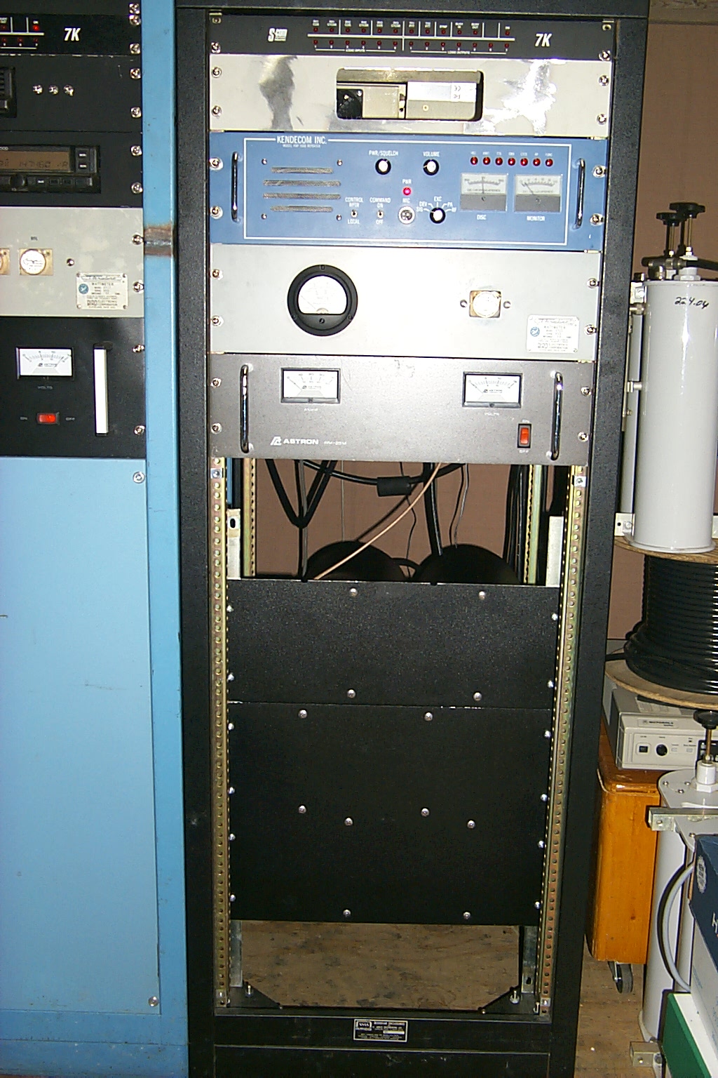
At this point I stopped working with the primary 224.040 repeater rebuilt in the new rack cabinet. I mounted the S-Com 7K controller, custom mount for the Kenwood TK-30 link radio, and left room for the rack mounted power supply. This second phase of the rebuild would have to wait until I completed work on the 146.940 Cumberland repeater.
Out in the light of day... and more importantly OUT OF MY HOUSE!

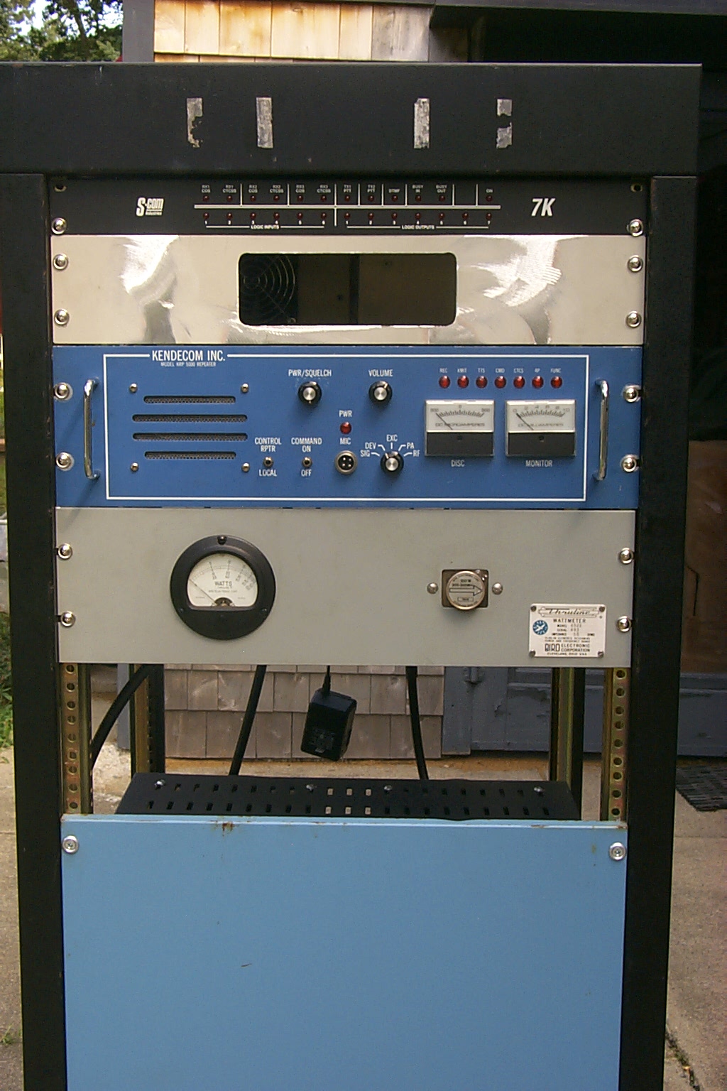
(click on images to enlarge)
Dad and I returned the rebuilt 224.040 repeater to the vault about 30 hours after I started tearing it apart in what can only be characterized as a "Marathon" repeater building session.
The next morning I chatted with Sandy on 224.040 during her ride into the Zoo. She was DFQ the entire trip and we had no trouble talking in areas where the repeater had been difficult to use in the past. I would say based on this initial testing the repeaters receiver performance is the best that it has ever been.
The addition work to install the link radio and tie 224.040 into the network will have to wait until after the 146.940 upgrades have been completed.
Update July 15th 2009 - Possible Lighting Damage?
After many months of flawless service providing the primary communications link for my wife KA1RXB the Lincoln 224.040 repeater suffered what is assumed to be a possible lighting related failure.
One of the Wacom cavities has either shorted out by a nearby lighting strike or was possibly damaged while I was crawling round in the rack cabinet. The cavity will no longer tune correctly and the duplexer has lost the necessary isolation to keep the transmitter from affecting the receiver.
I instinctively reached out to my friend Jag and asked him to look for some matching Sinclair BP/BR cavities like the two Sinclair BP cavities I has purchase from him in 2007 for this repeater. My plans are to build a new six cavity Sinclair duplexer for the repeater.
(click on images to enlarge)
After some friendly email exchanges and a phone call to seal that deal a check was "in the mail" on the way to Clay in Tennessee and soon some shiny new Wacom cavities will be arriving here in Rhode Island.
The moment they arrive I will attempt to get these new cavities re-tune for the 224.040 / 222.440 frequency pair and get the repeater back on the air right away.
So now the race is on! Which cavities will arrive in Rhode Island first? Which cavities will tune up and perform the best on the 224.040 frequency pair? And which cavities will fit best in the repeaters rack cabinet...
Stay tuned for the answers to these interesting questions and MORE!
Update July 17th 2009 - The Race is on
Who's cavities will arrive first? Will it be Jag from Canada or Clay from Tennessee? While everyone is placing their bets to see which set of cavities arrive in Rhode Island first...
... A third horse enters the race!
Lou N1UEC contacted me after hearing about the duplexer problems and has charged into the race by tuning a "loaner" set of cavities to get the repeater back on the air while the other two sets of cavities are rumbling across the country on different trucks.
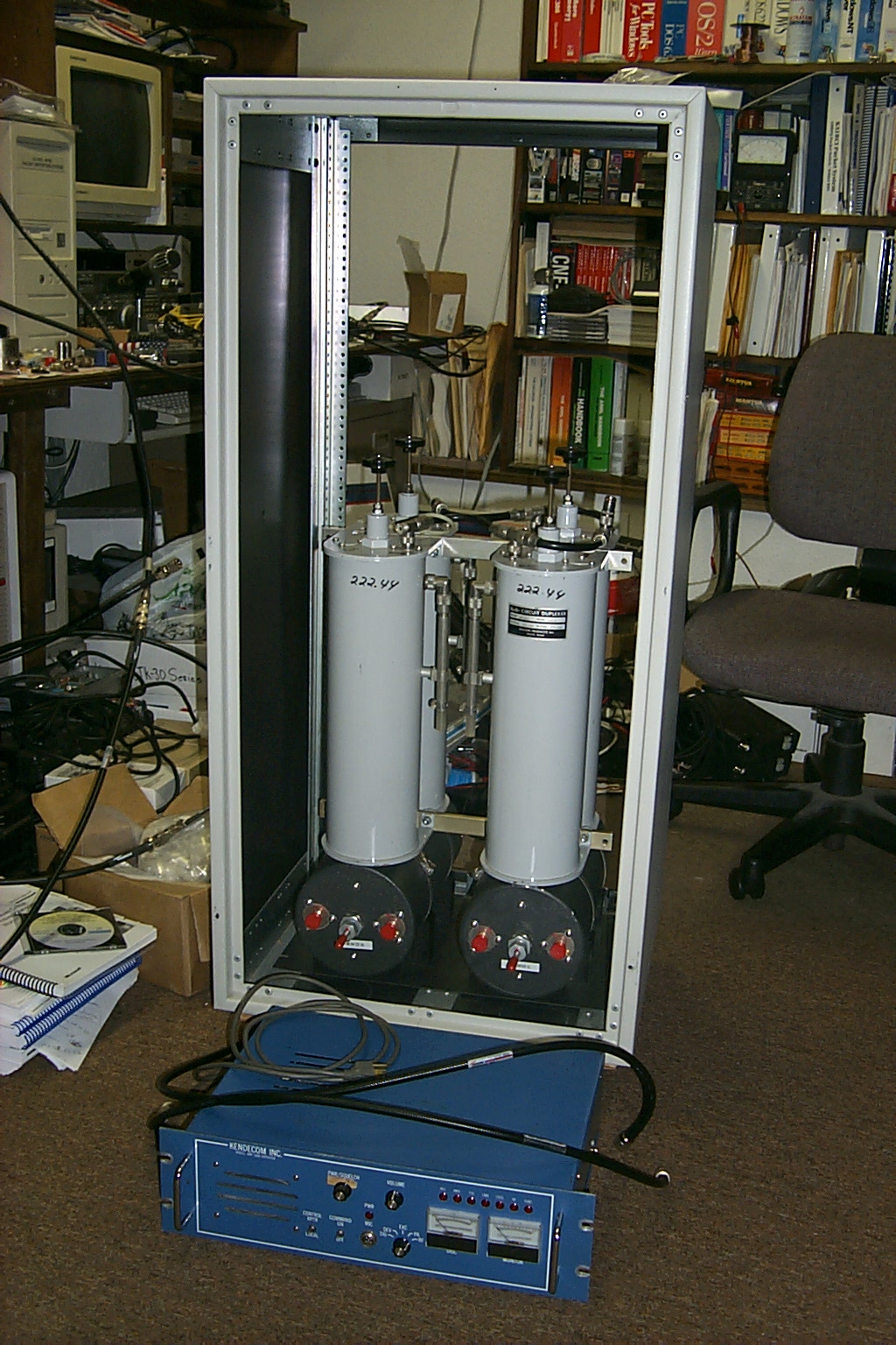
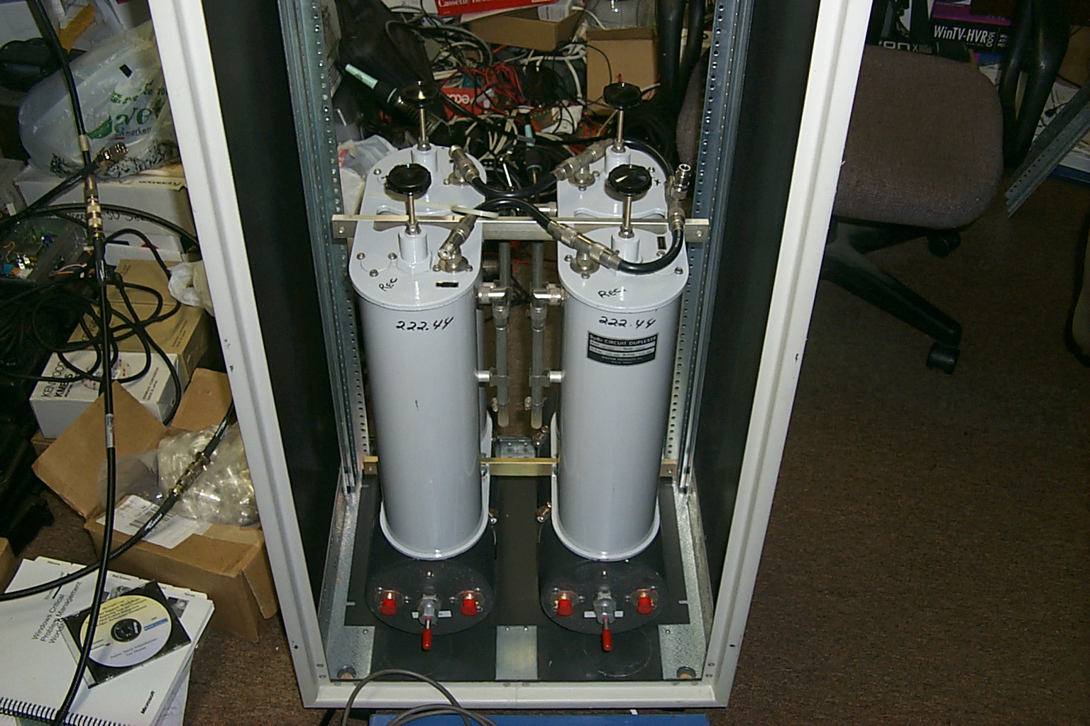
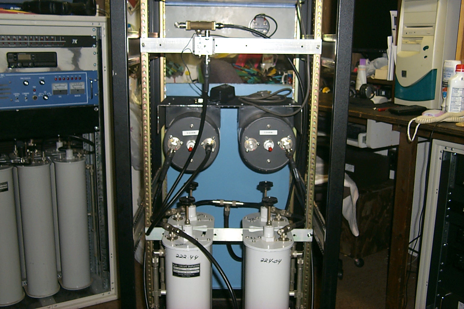
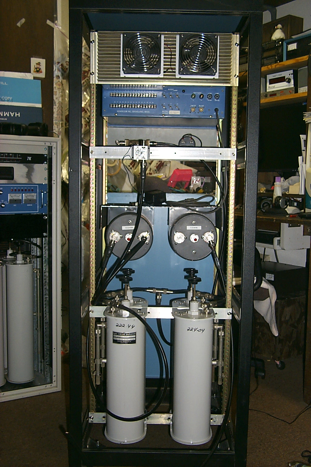
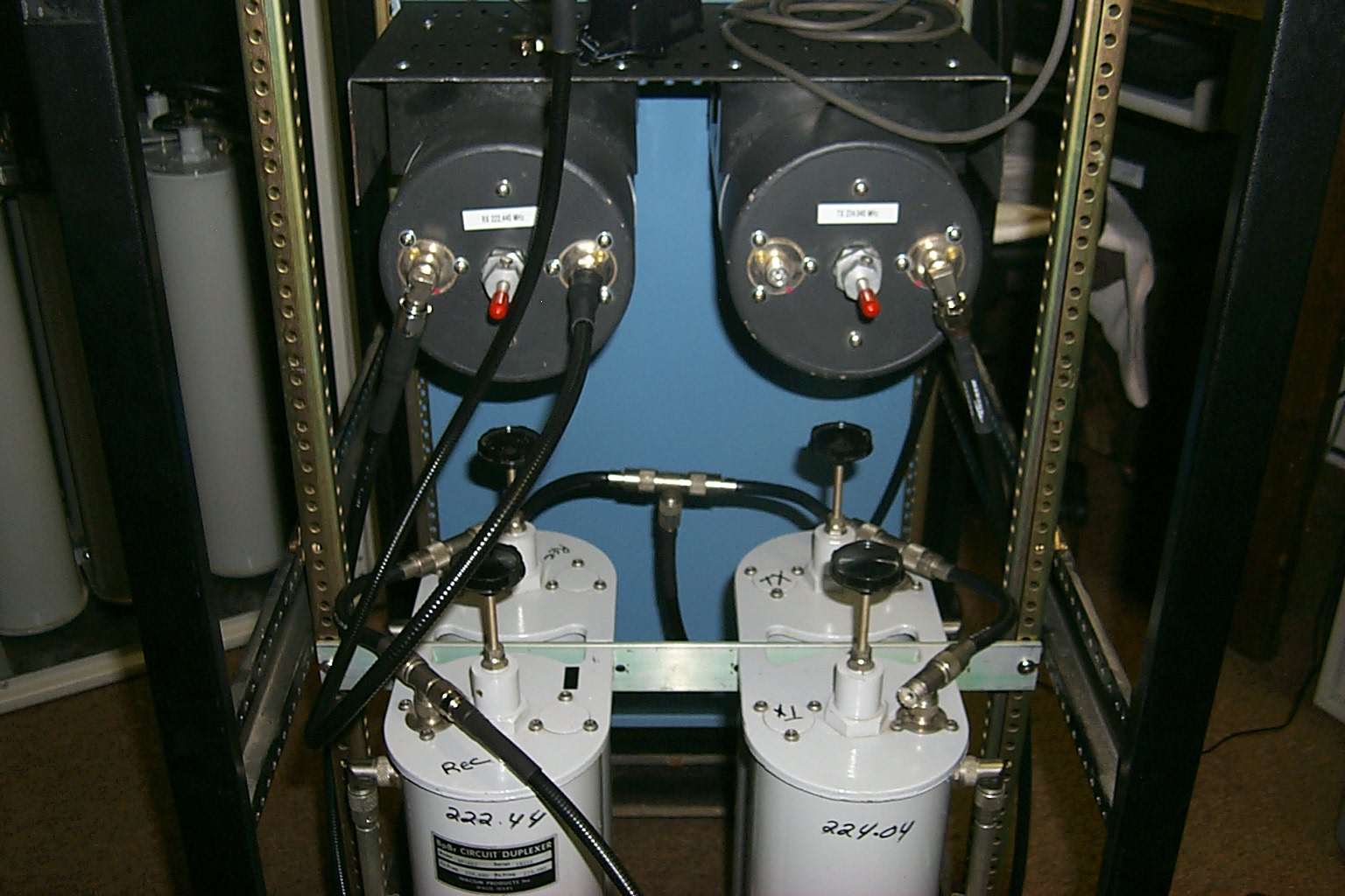
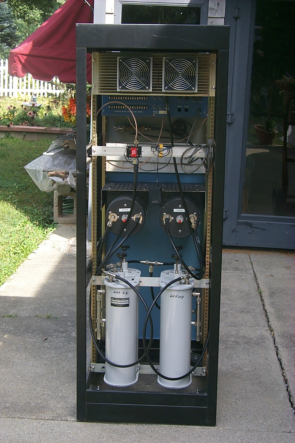
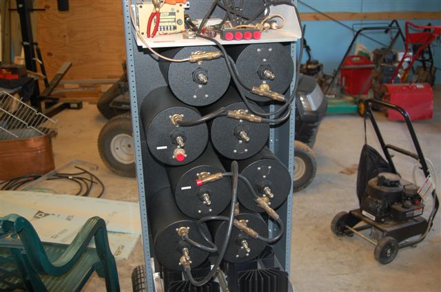
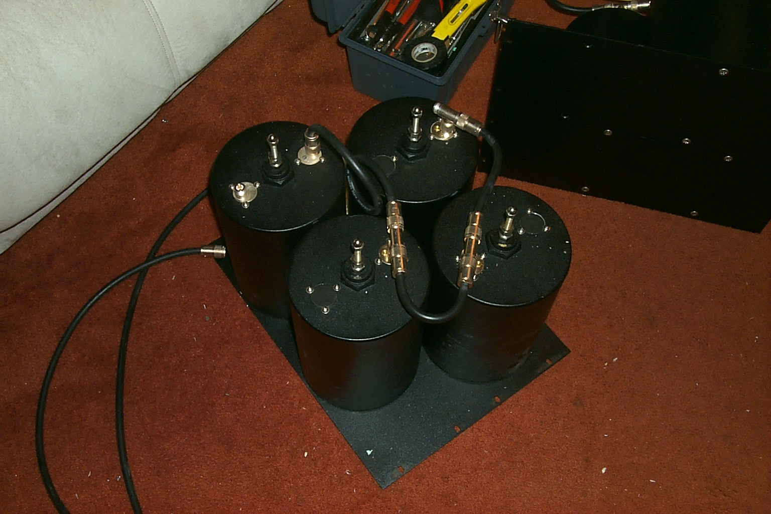
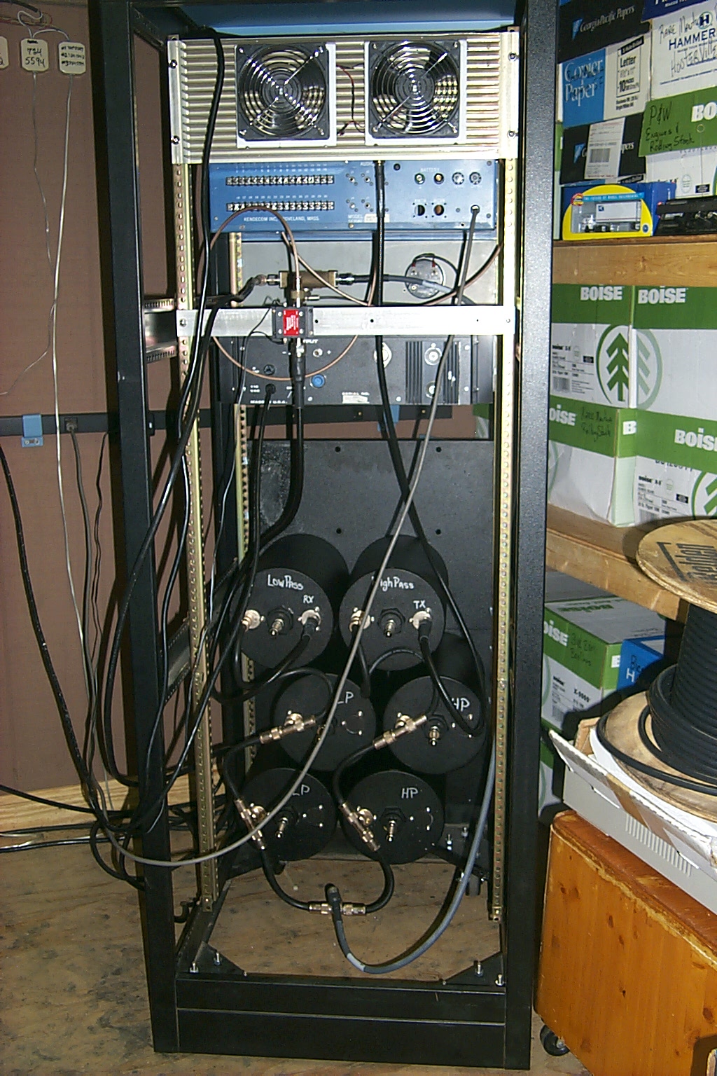
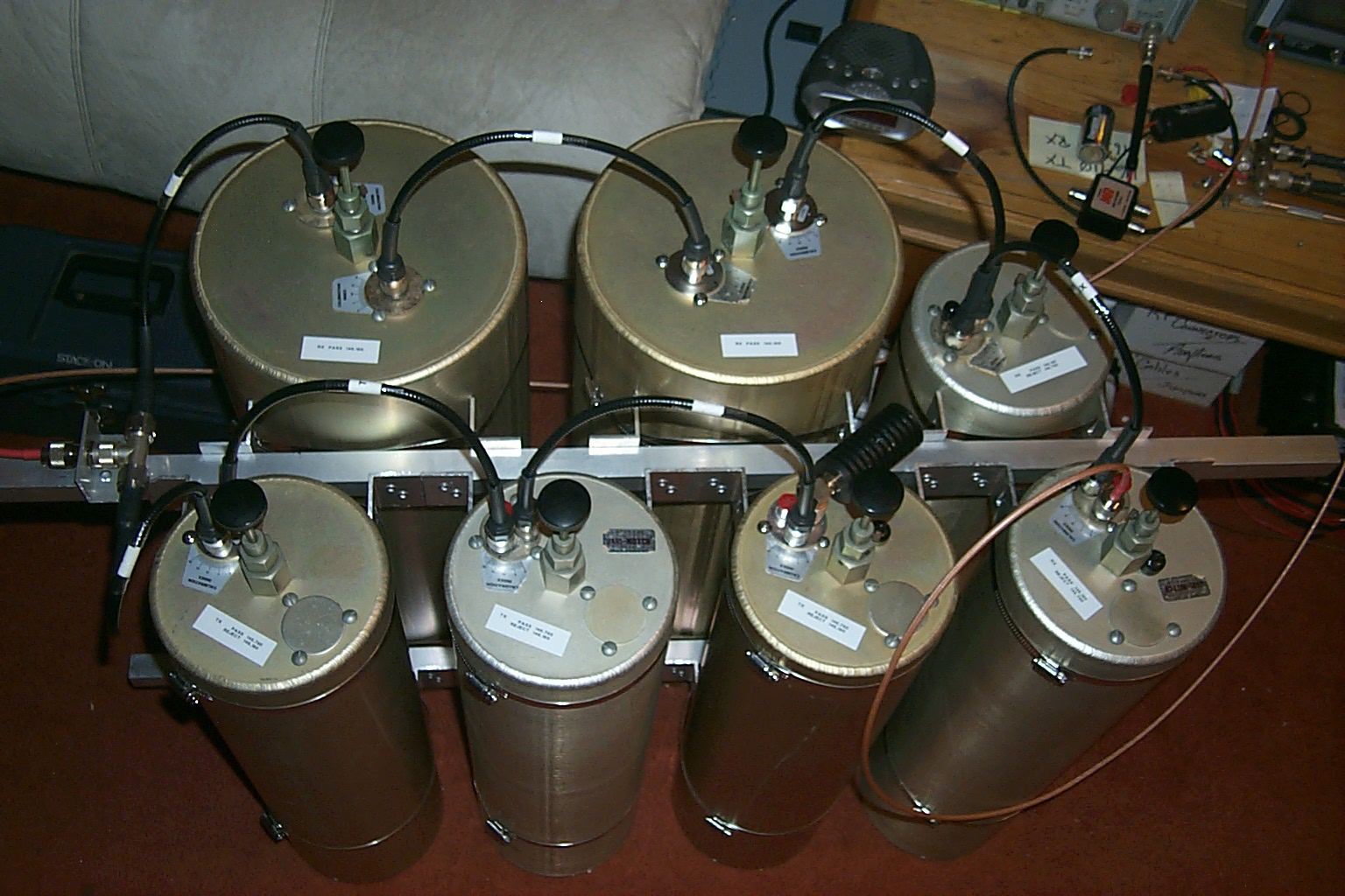
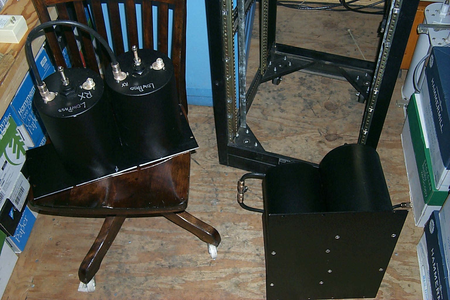
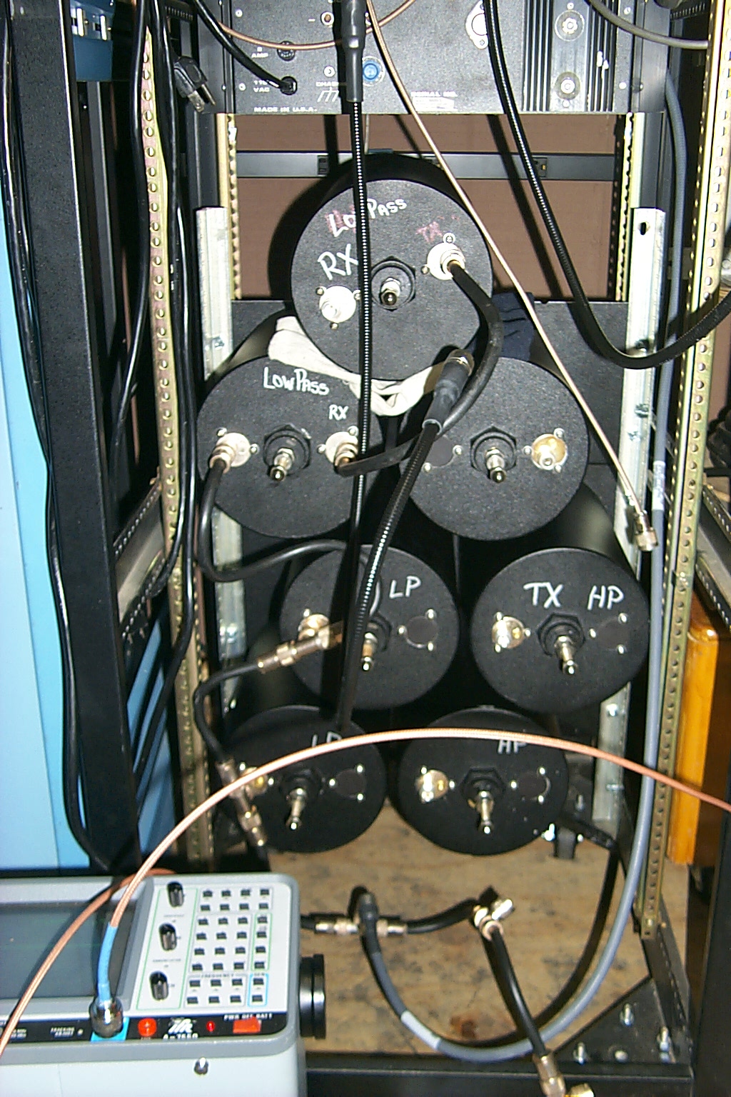
Back on the air... 9:30PM Friday evening July 17th the 224.040 repeater was back on the air using the loaner set of cavities from N1UEC. In these photos you can see the loaner set of cavities from Lou sitting on the floor inside the rack cabinet and the original Wacom cavities disconnected in front of the rack. I can not see any signs of damage on the Wacom cavities so maybe whatever is wrong can be repaired.
224.040 Version 3.205b (beta) "the loaner cavities"
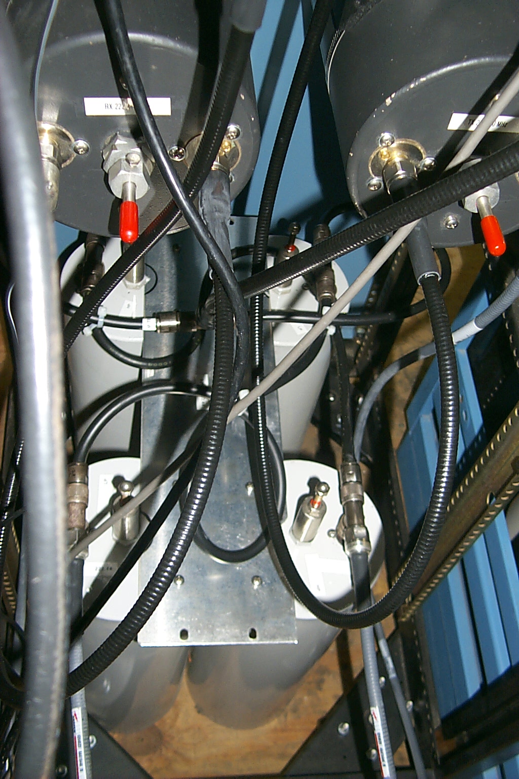
(click on images to enlarge)
Clay's Cavities from Tennessee have arrived...
The repeater had been running on Lou's loaner set of cavities for about a week when the Wacom cavities I picked up from Clay arrived. These Wacom cavities were in wonderful condition and I was very pleased.
(click on images to enlarge)
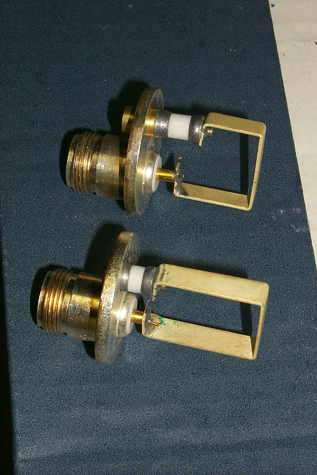
Unfortunately one of the Low Pass cavities had a problem, the band pass tuning rod has become disconnected from the plunger so I was not able to adjust the tuning on this one cavity...
Clay is sending me a replacement cavity out right away... (outstanding customer service!) LOL
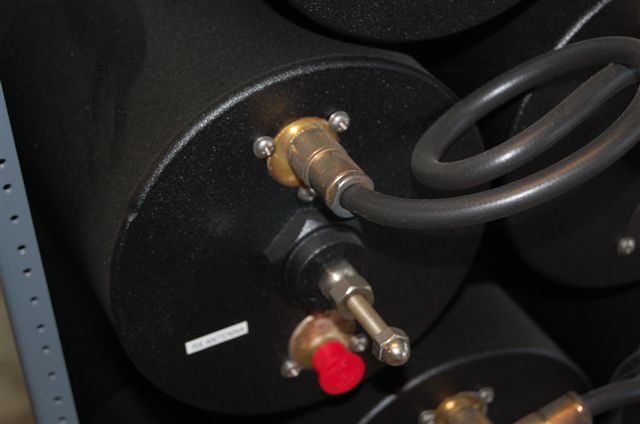
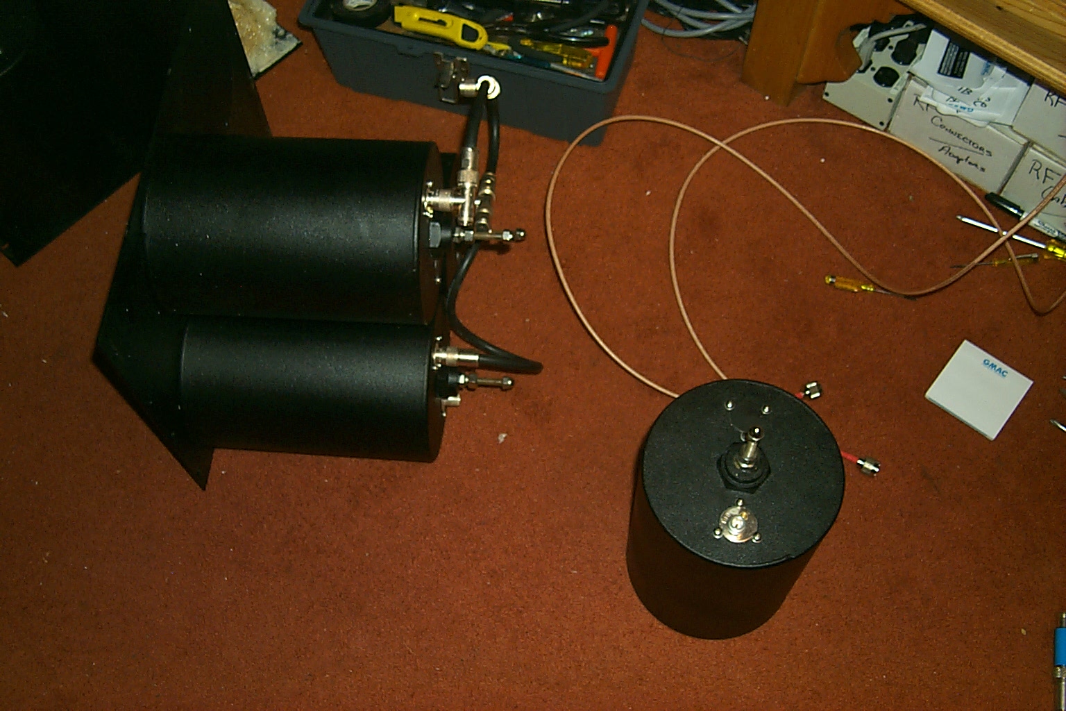
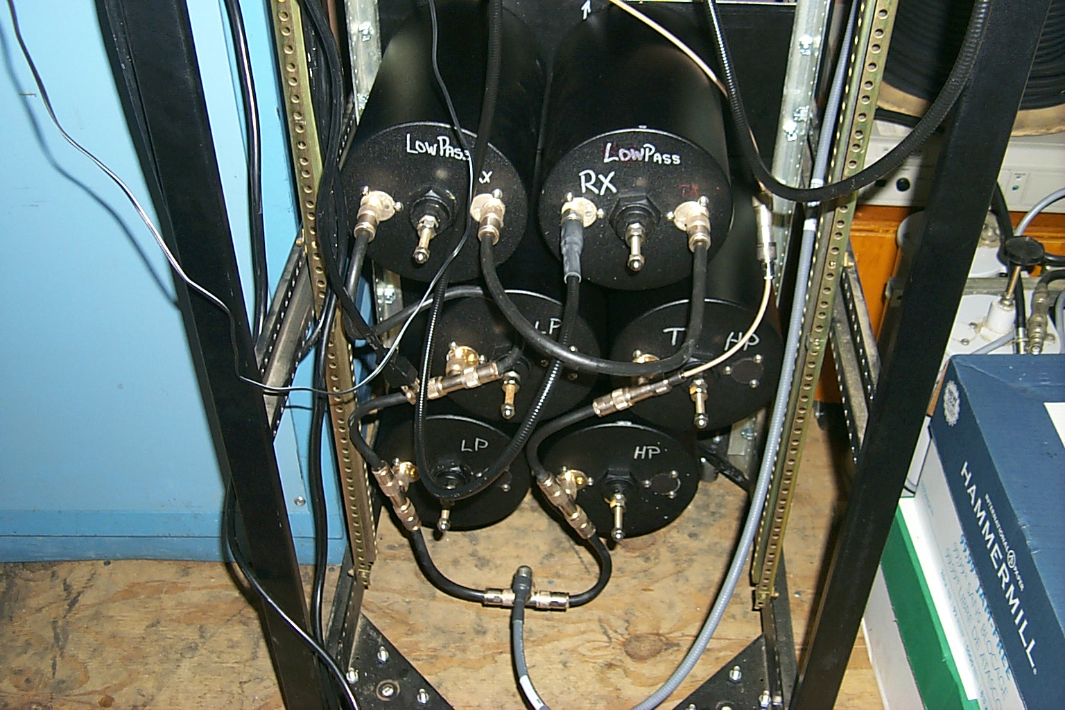
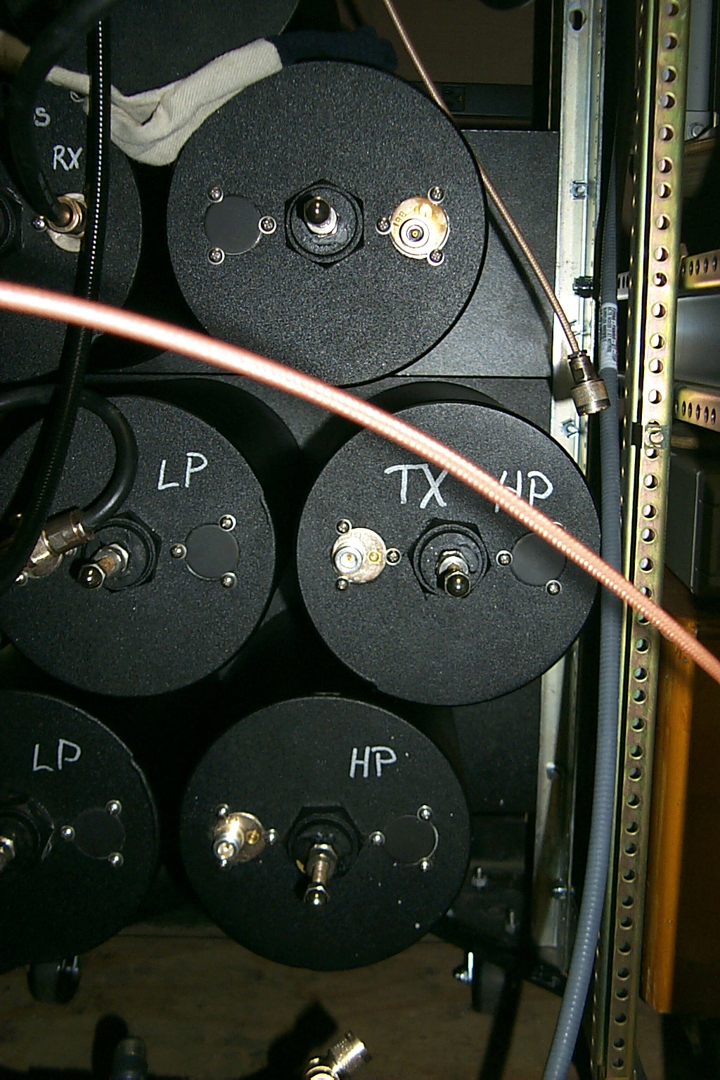
The original mounting configuration for the PreSelector had the four High Pass cavities on one mounting plate and the four Low Pass cavities all mounted on another plate.
So I did have to remove all the cavities from the mounting plates and move them around so the phasing harness would fix in the new duplexer configuration.
In this group of photos I am working out the final configuration and getting the cavities tuned to my frequency pair. They tuned like a dream right on 224.040 / 222.440 MHz with little effort.

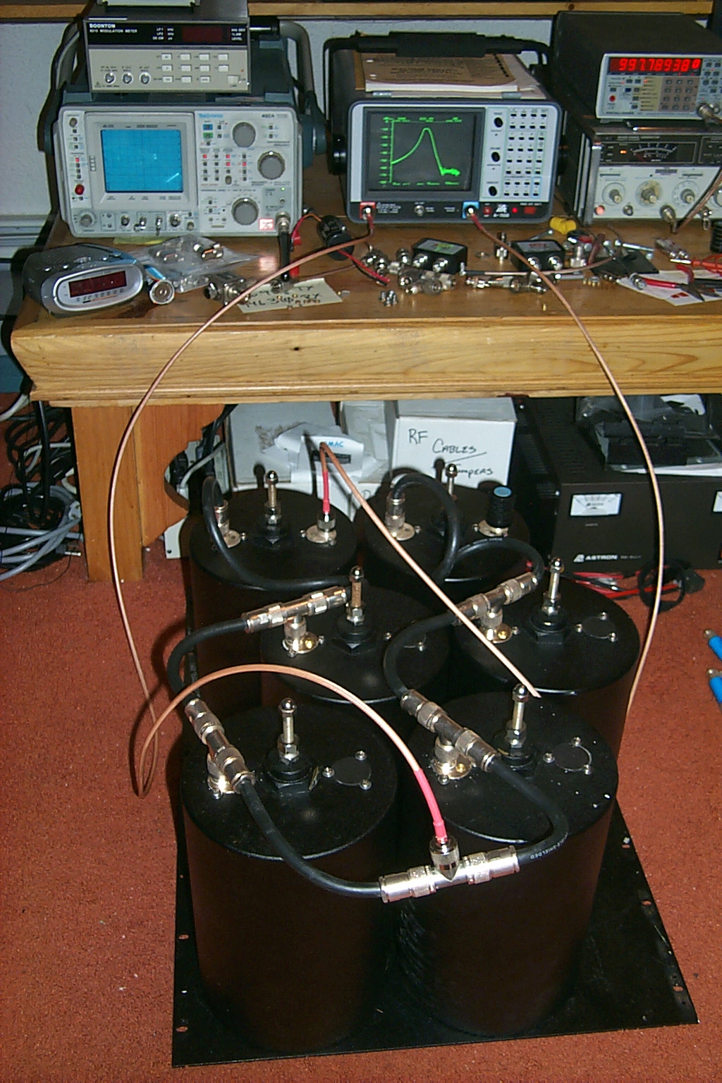
(click on images to enlarge)
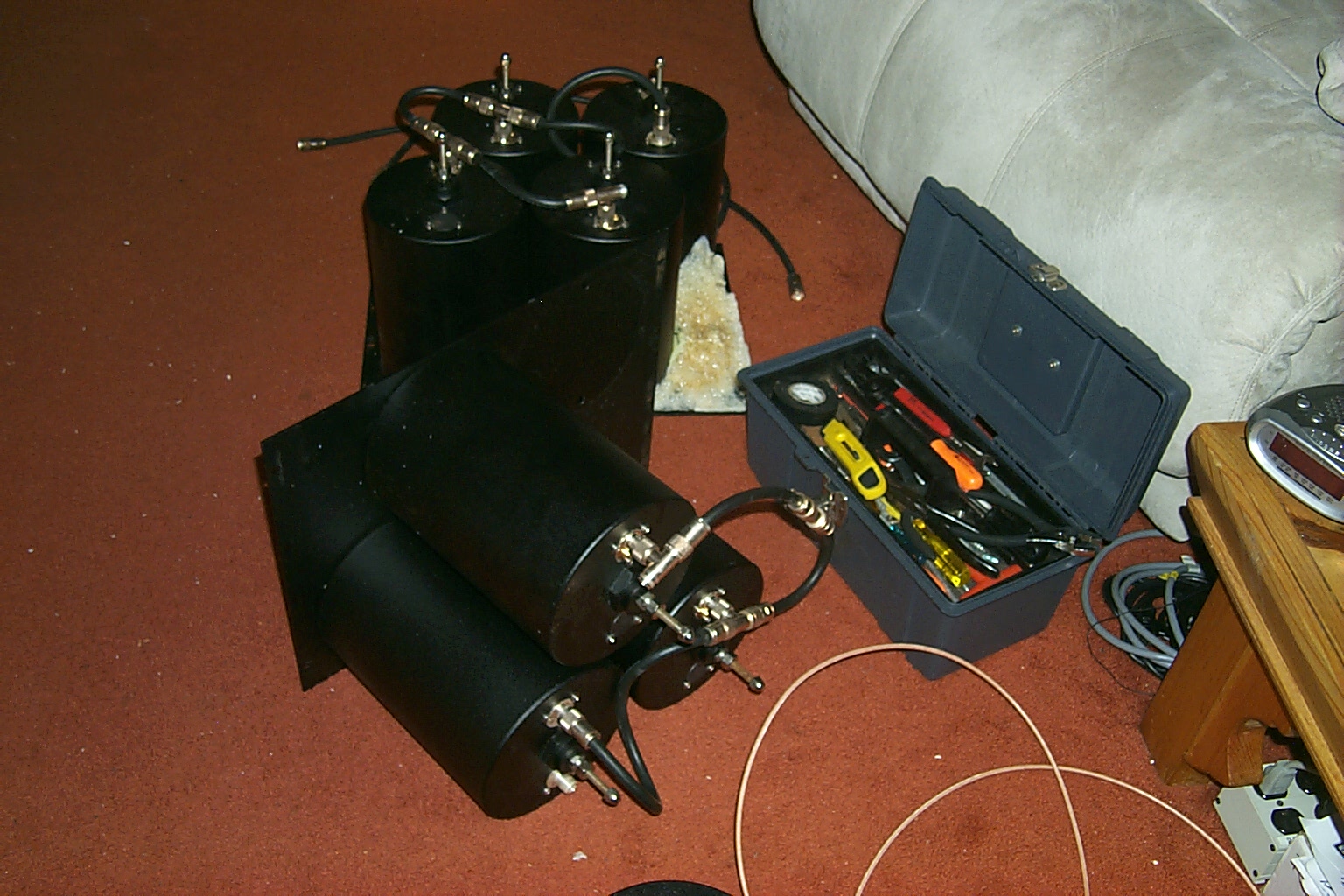
In this next group of photos I have already removed the loaner cavities from Lou and I am about to remove the band pass cavities from Jag in preparation of mounting the new Wacom cavities from Clay in the rack.
(click on images to enlarge)
February 2010 Temporary Antenna
The Diamond X3200A that has been on the tower for 18 years finally failed during a bad winter storm in Dec 2009. The fiberglass random snapped at the base of the antenna right at the mounting point to the tower and it is dancing around in the wind causing very bad crackling on the receiver... (PIM)
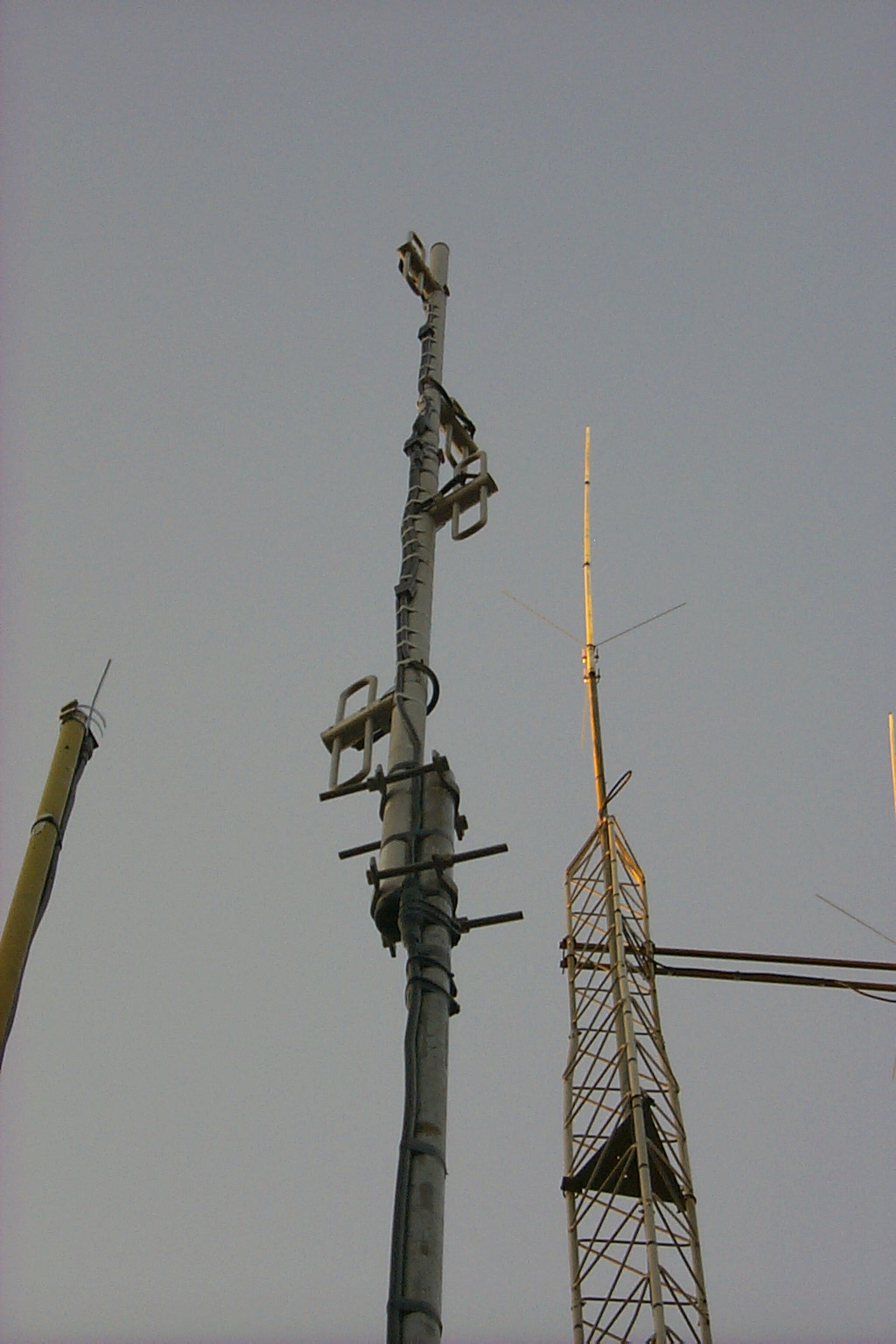
I was able to purchases a few used commercial 220 MHz antennas from a local radio shop and with help from several friends my father and I were able to get one a very nice exposed four dipole array installed in a temporary configuration to keep the repeater on the air until I can get the 80 foot tower down safely and replace the damaged antenna.
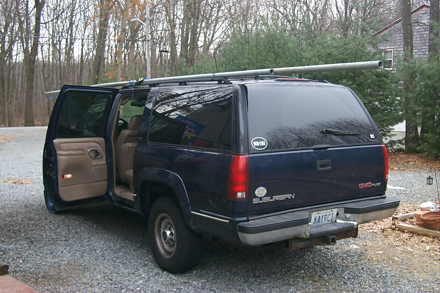
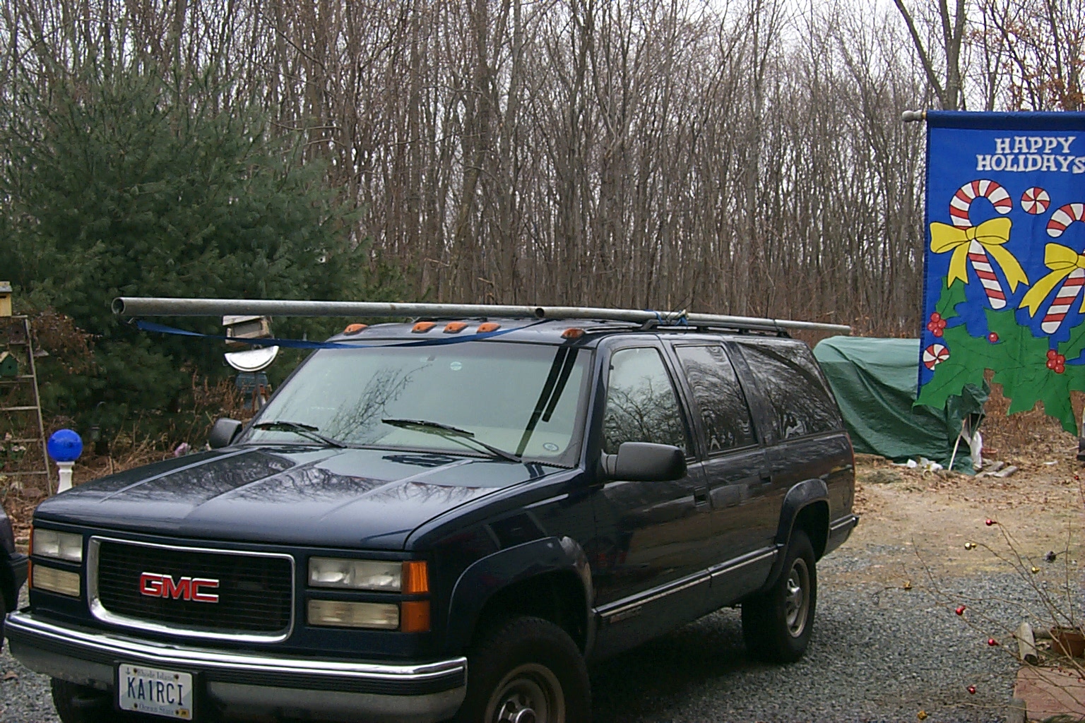
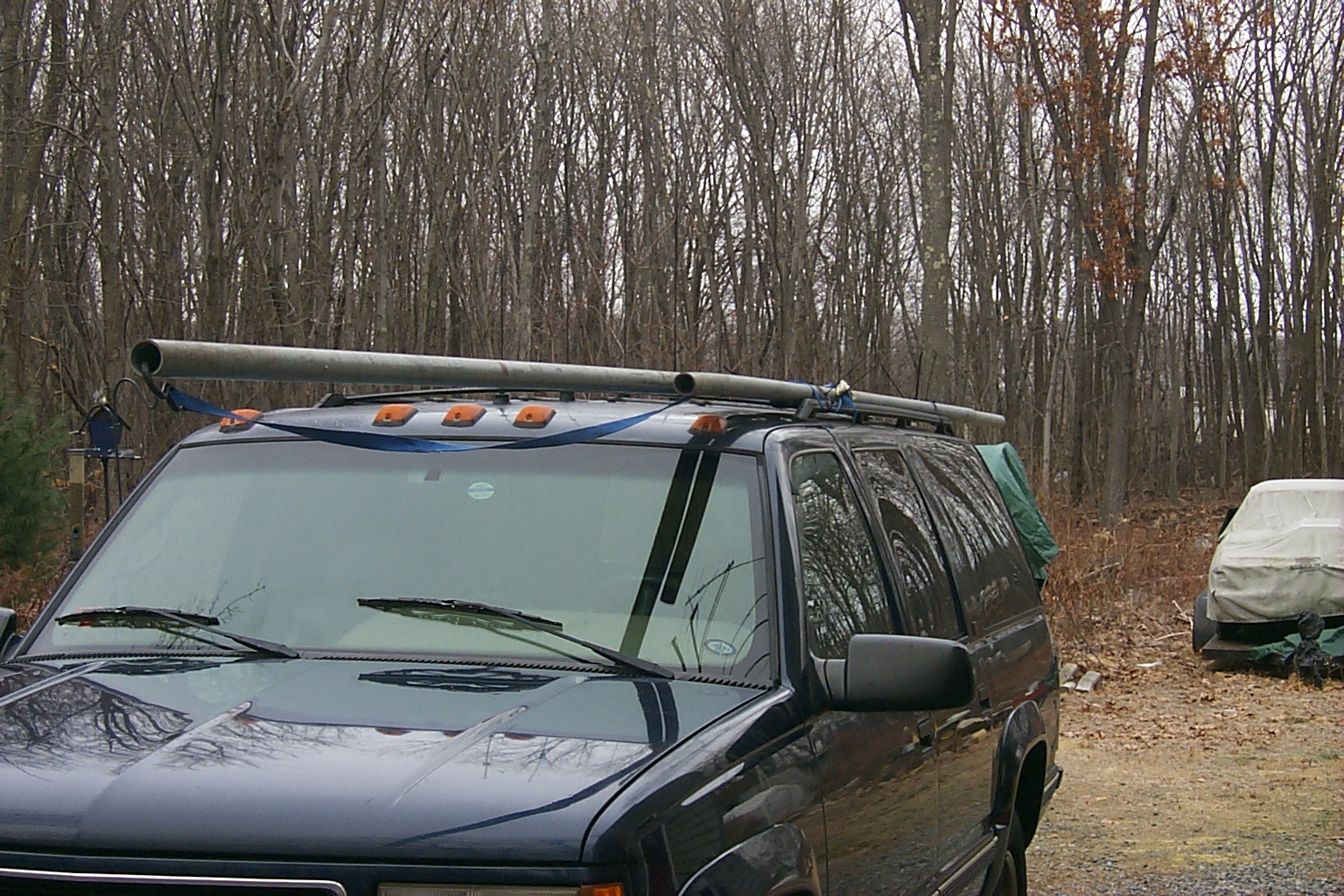
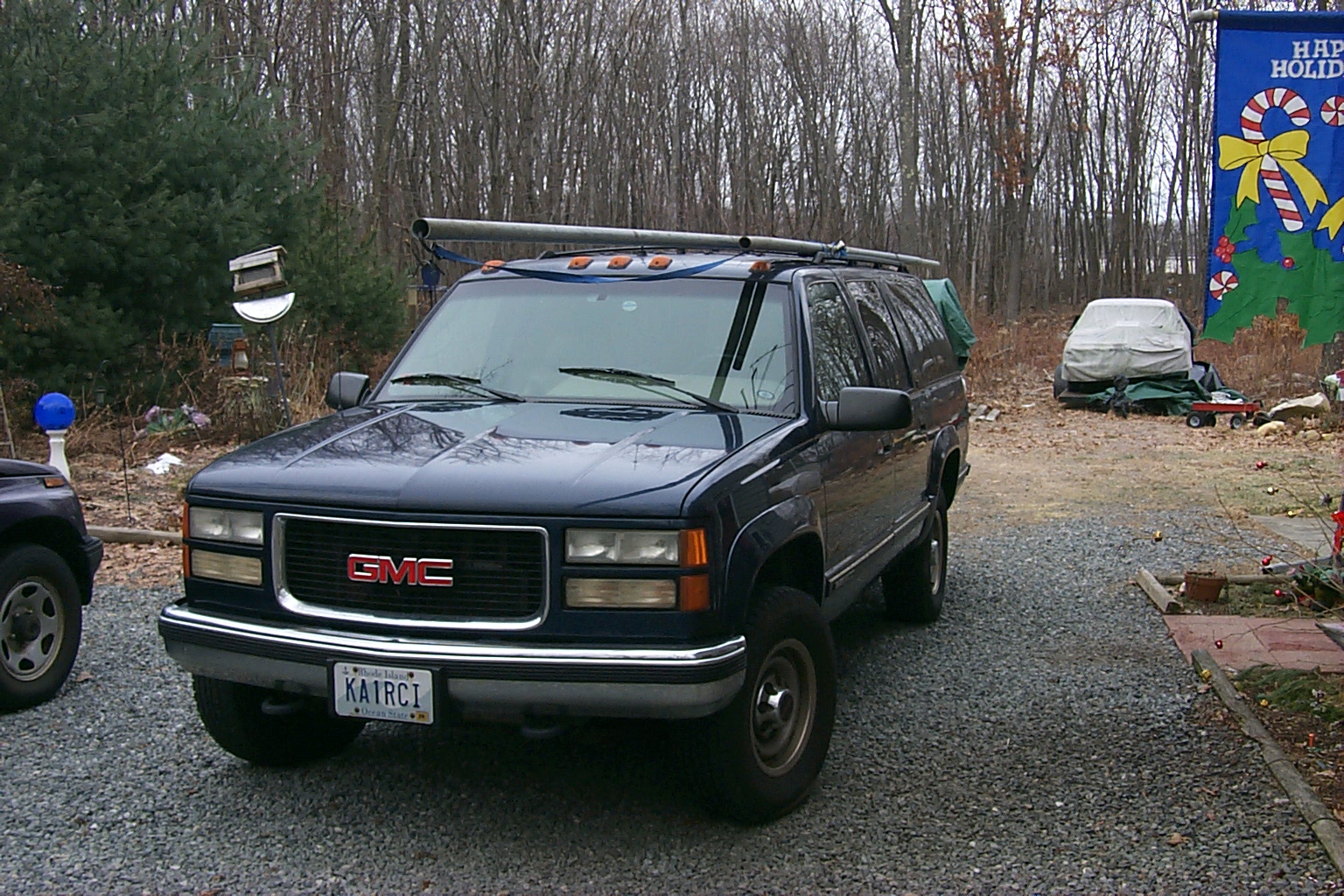
In these photos I had just brought the used commercial 220 antennas and the 24 foot mast home.
(click on images to enlarge)
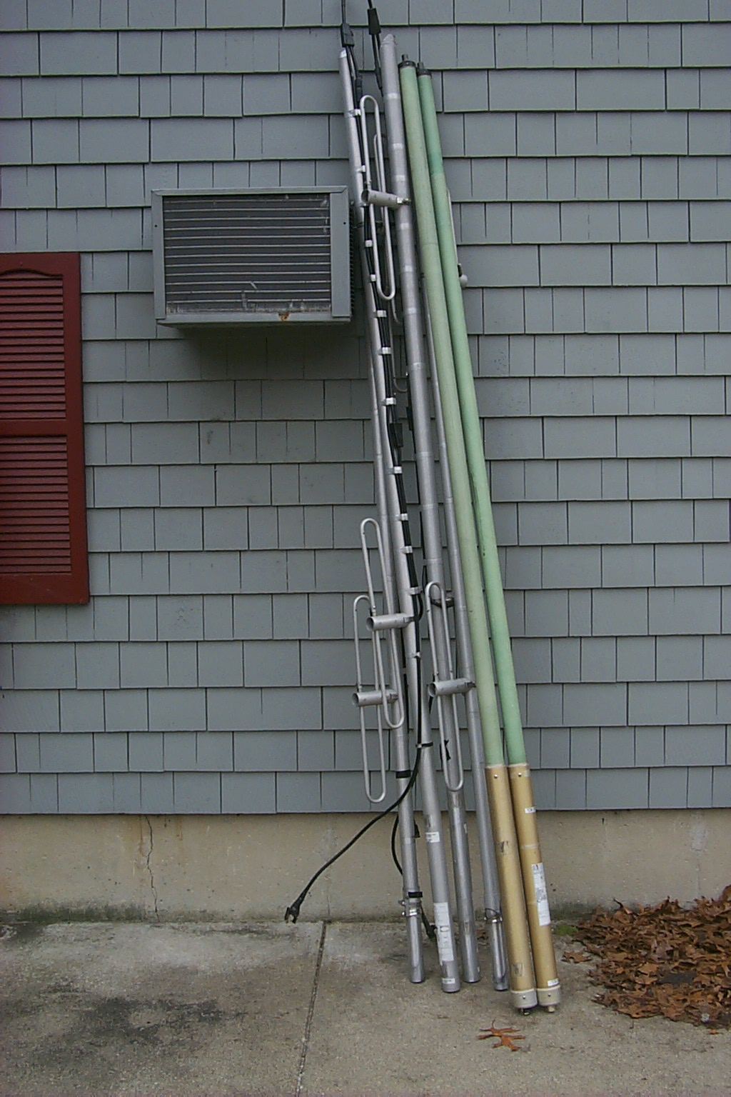

The four used 220 MHz antennas that Pete AA1PL help me purchase from a local radio shop.
(click on images to enlarge)

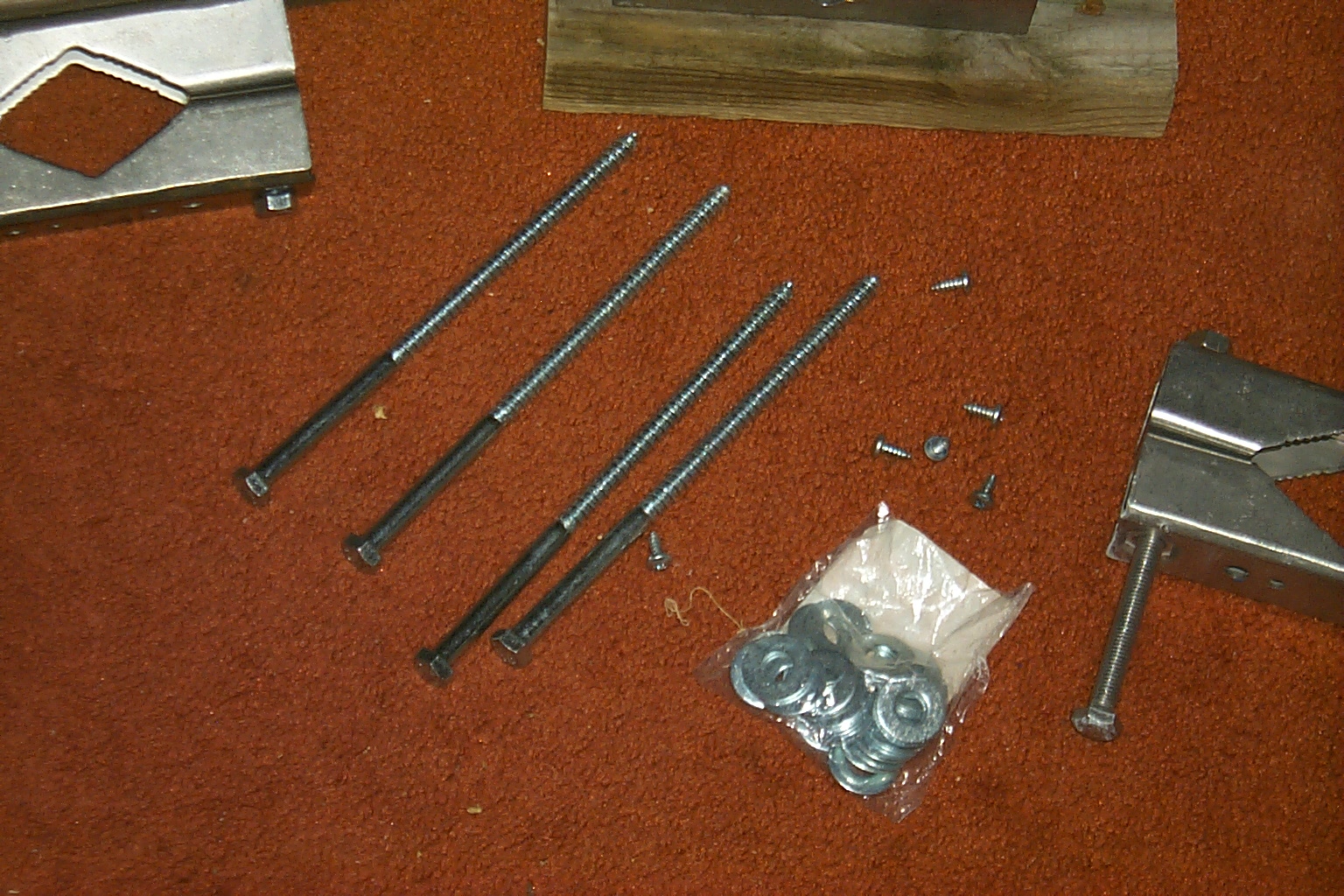
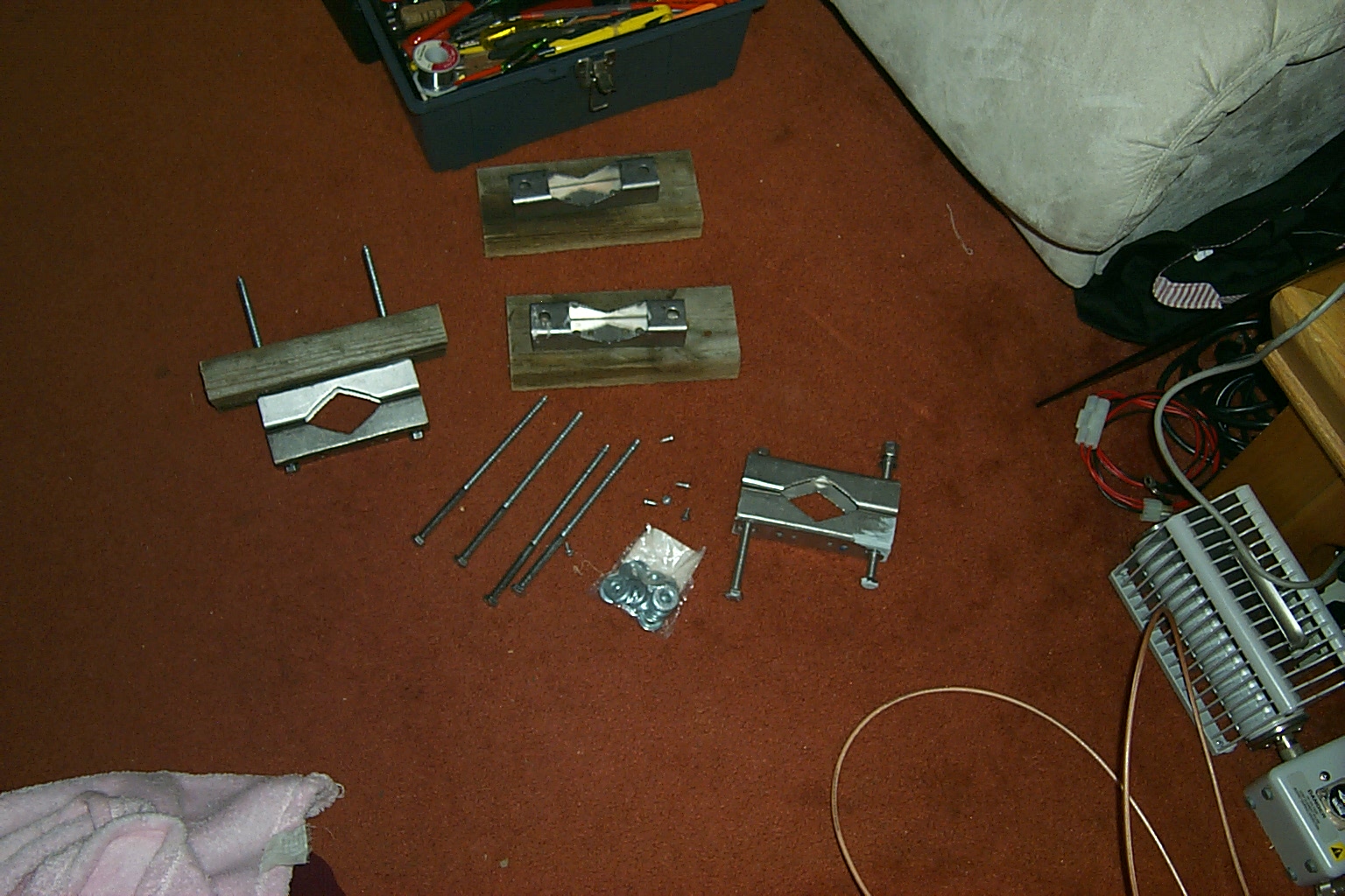
Roland N1JOY donated six very nice mounting brackets and Bruce KD1BE was able to make some pressure treated boards to give the mounts the required clearance and add strength. I stopped at the local Home Depot and purchased the extra long lag bolts to secure the 24 foot mast to the side of the repeater shed.
(click on images to enlarge)
Mounting the mast to the repeater shed
Roland N1JOY donated six very nice mounting brackets and Bruce KD1BE was able to make some pressure treated boards to give the mounts the required clearance and add strength. I stopped at the local Home Depot and purchased the extra long lag bolts to secure the 24 foot mast to the side of the repeater shed.
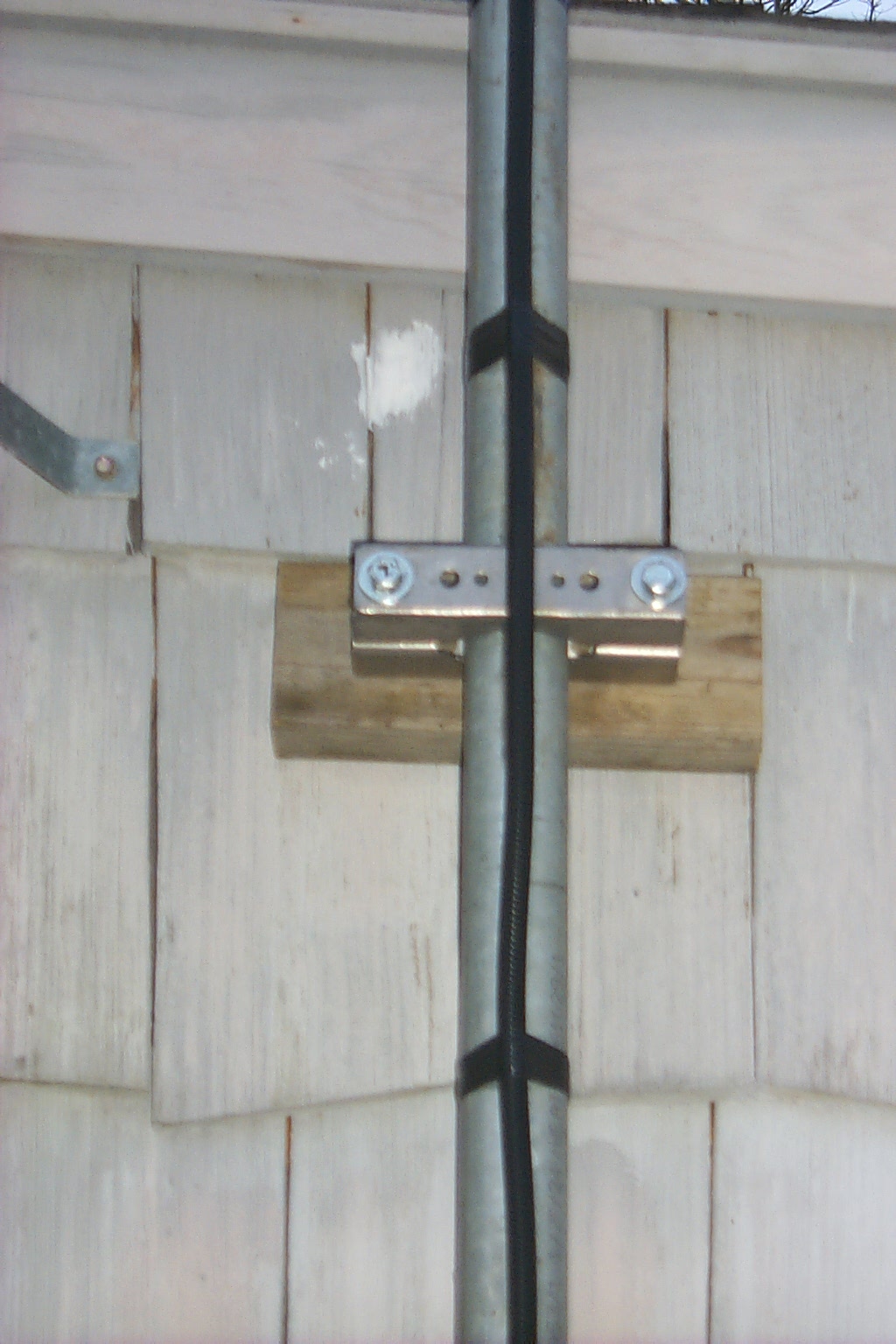
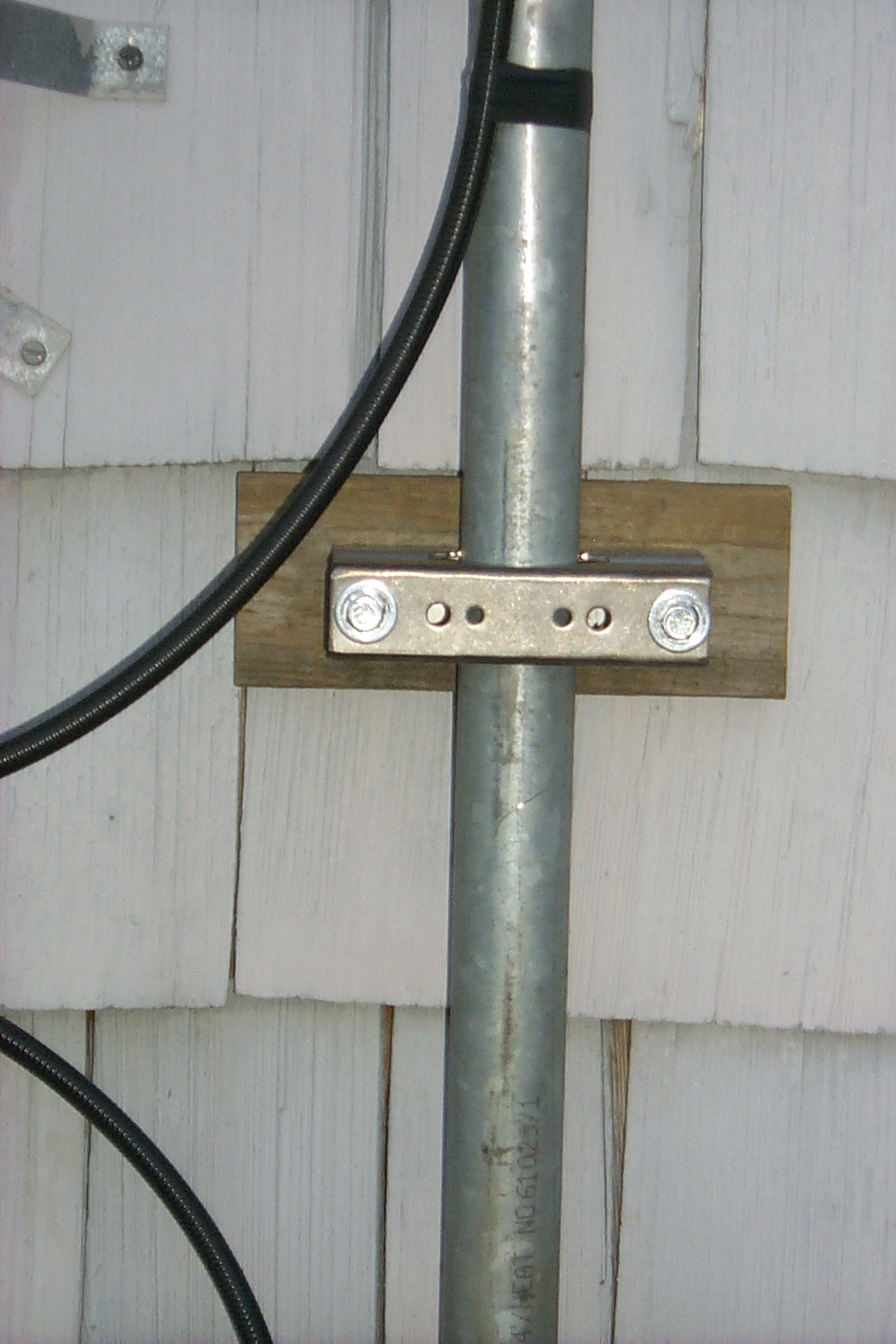
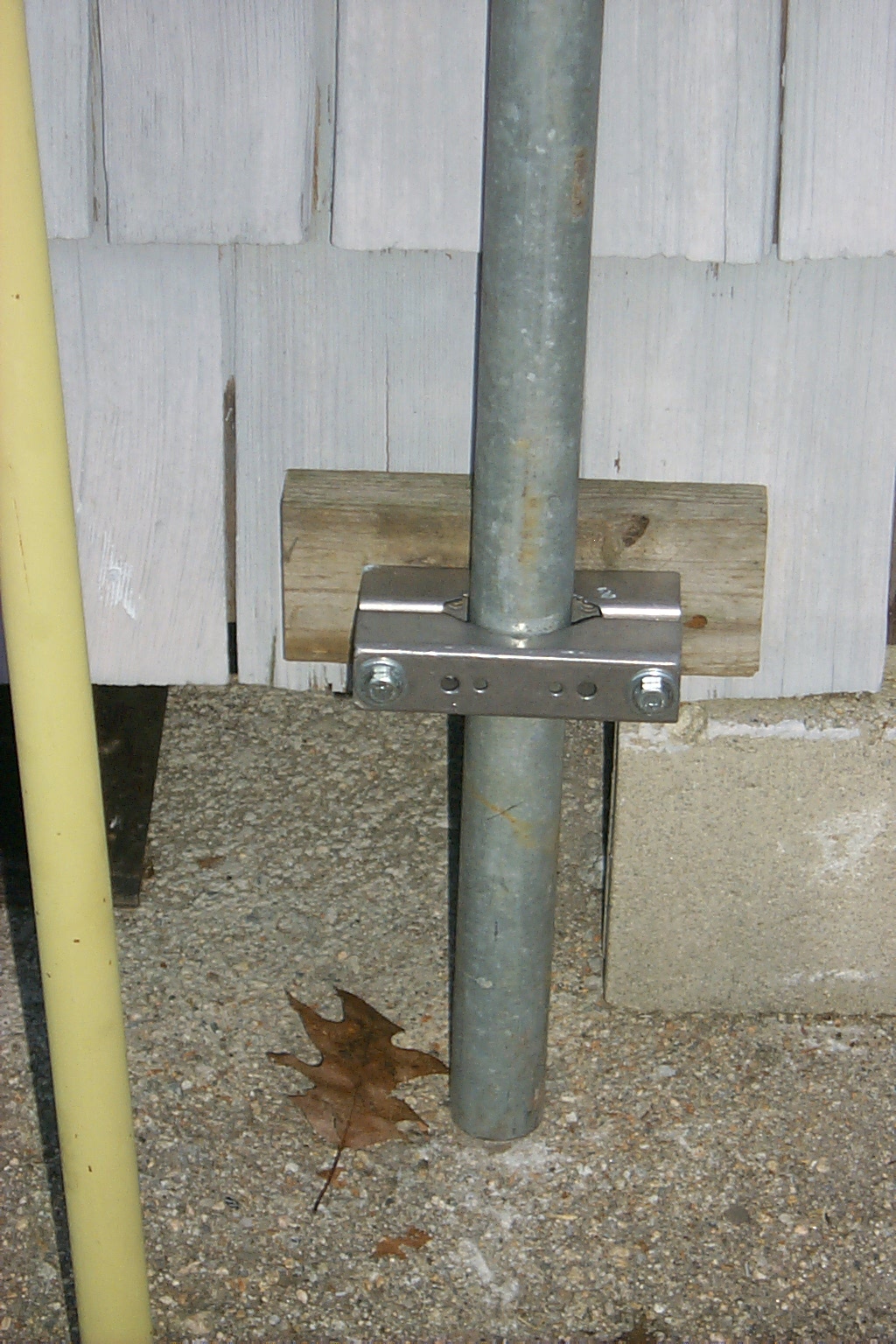
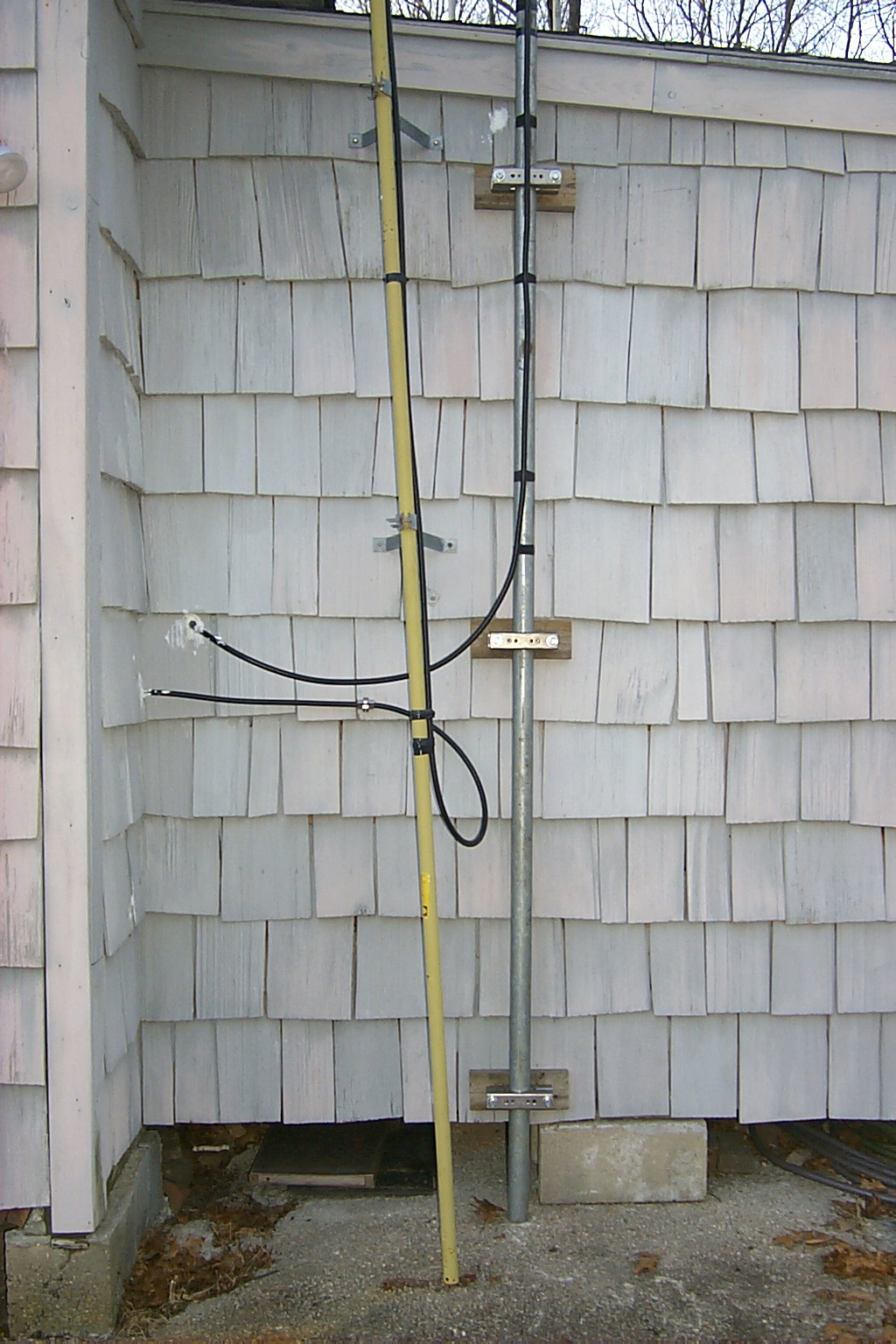
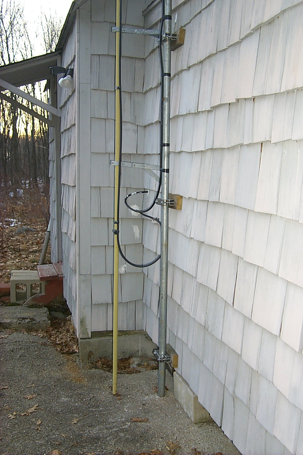
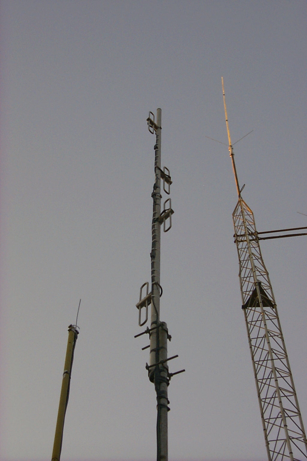
Dad and I were able to secure all six brackets at three evenly spaced points on the side of the repeater shed to hold the 24 foot mast. Then we assembled and mounted one of the commercial 220 MHz four dipole exposed array antennas to the mast. We both narowlly escaped trips to the emergency room getting the 44 feet of mast and antenna vertical... The antenna and mast were much heavier and harder to maneuver than I had anticipated.
(Next time MORE HELP will be needed before trying a stunt like this)
We did however get the new temporary antenna vertical and bolted into the mounts.
In these photos you can see the new 220 MHz dipole array with the tower in the back ground. The new temporary antenna has a great VSWR and there is no more crackling / PIM problems.
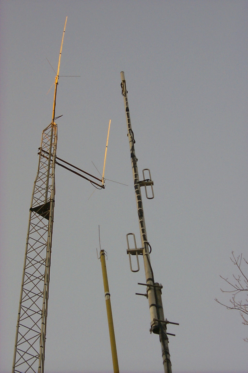
(click on images to enlarge)
February 2010 Duplexer reconfiguration
Over the Christmas 2009 / New Year 2010 holiday season Roland N1JOY, Pete AA1PL, and I spent many hours upgrading the 146.760 repeater located in Situate, RI. During these activities Roland & I worked with Brian N1BS during a marathon session tuning the new cavities for the .76 duplexer in the middle of my living room. We spend hours trying different coupling loops and configurations but could not get the performance that we expected.
This are photos of the 146.760 duplexer during our marathon tuning session...
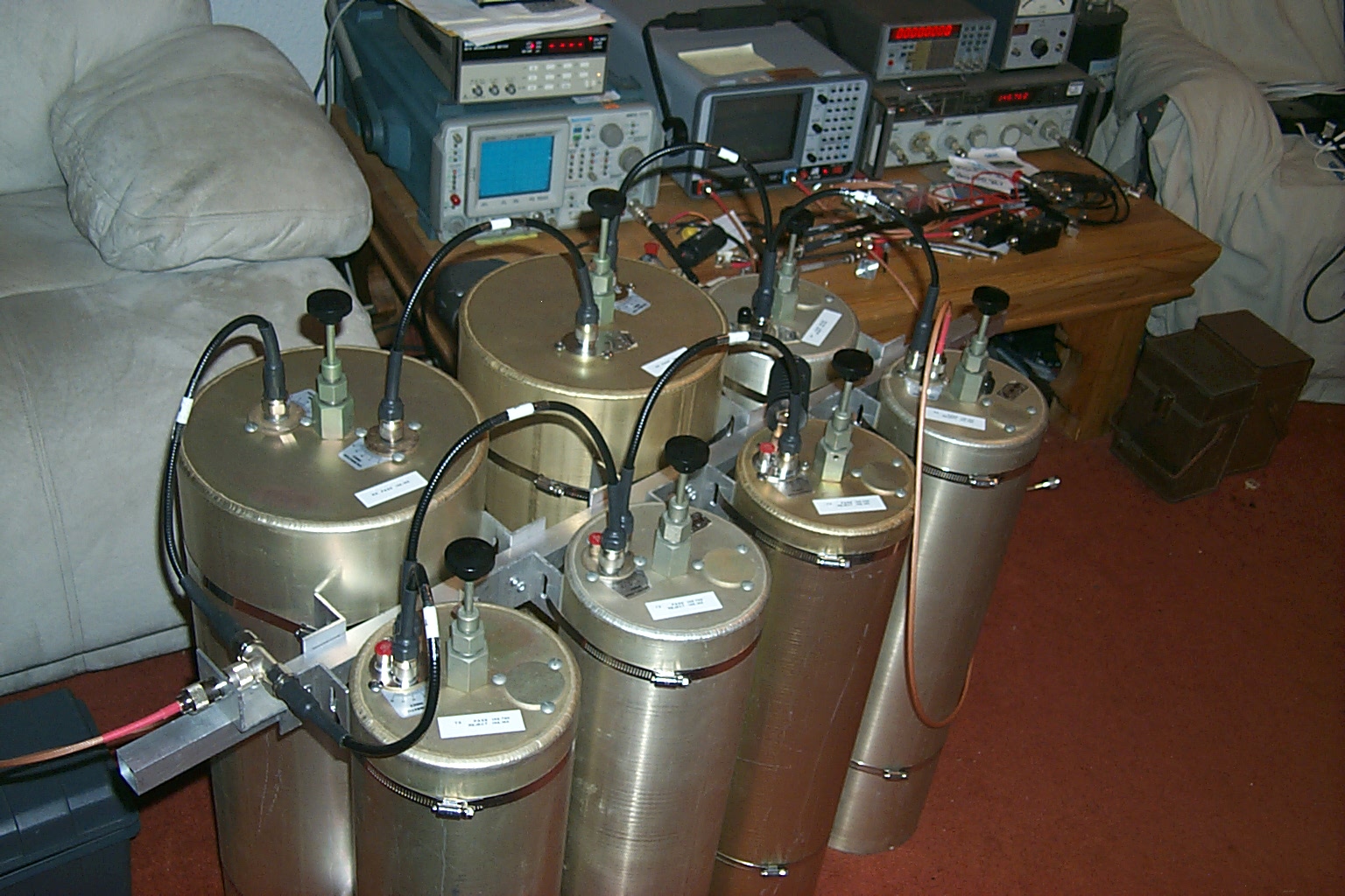
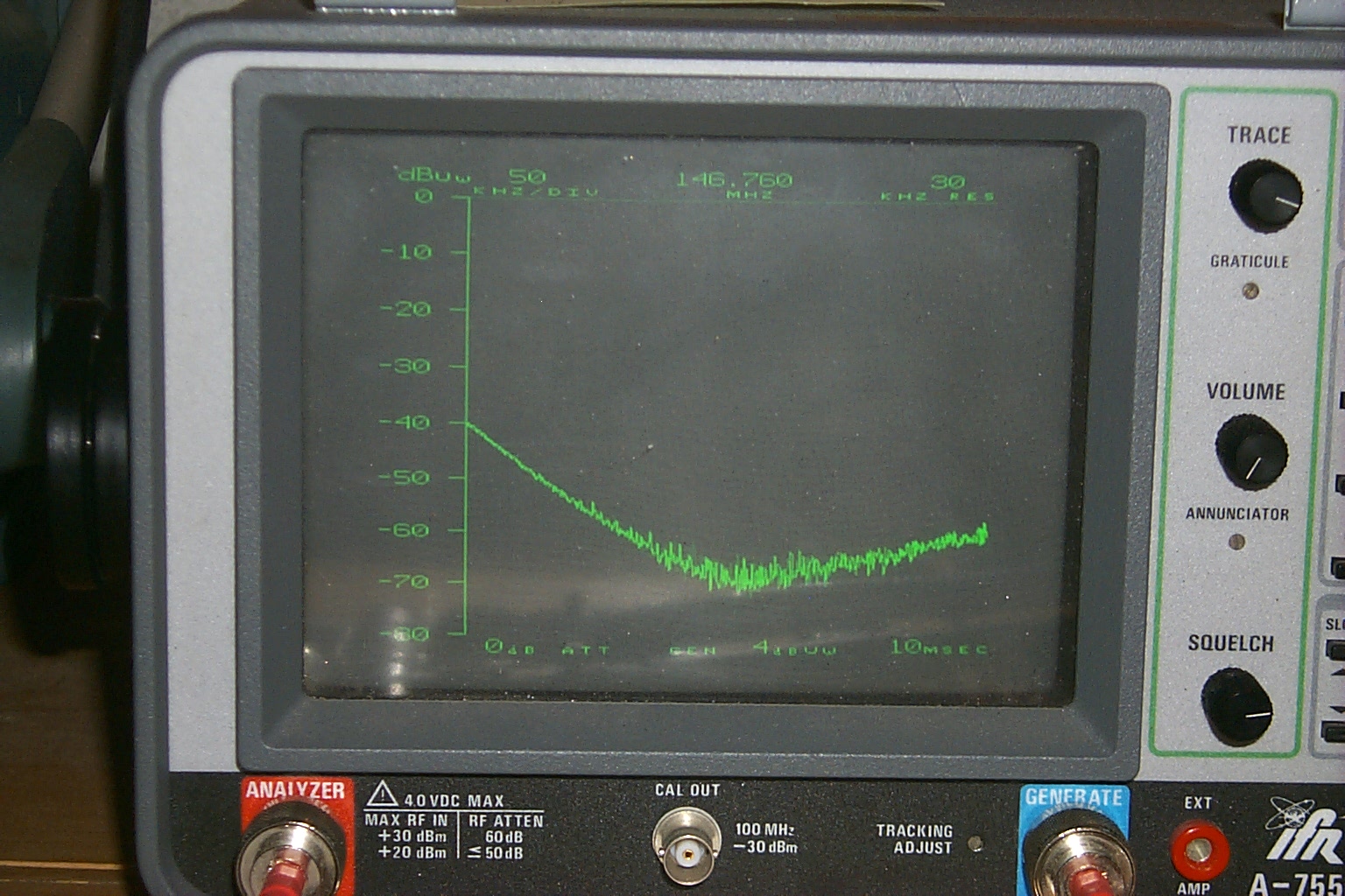
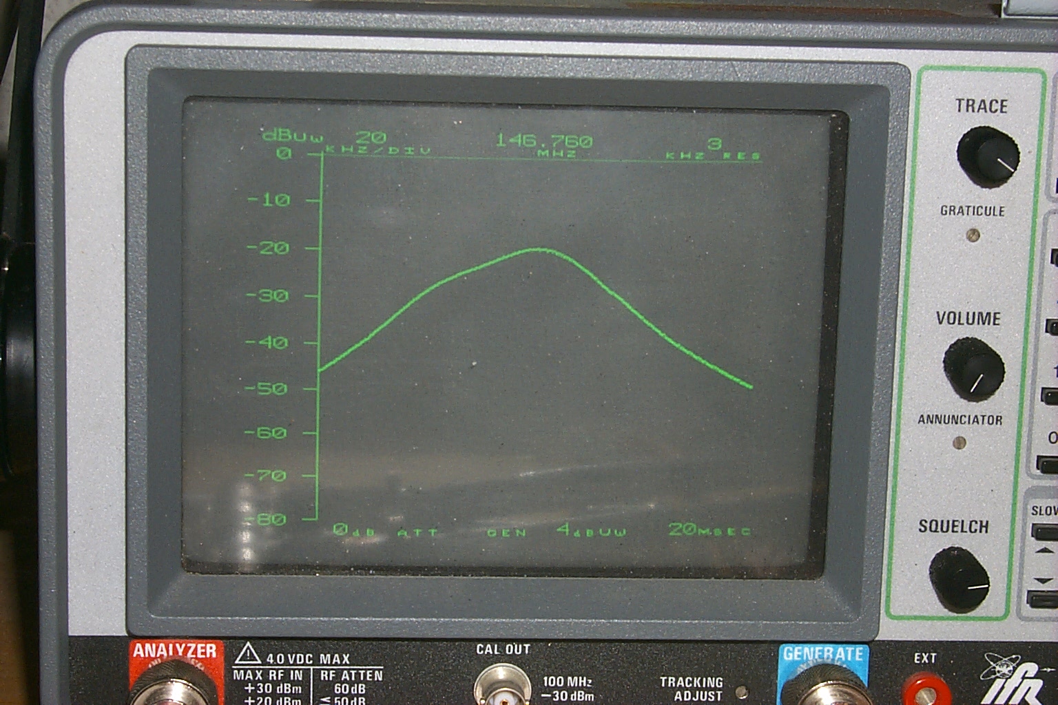
(click on images to enlarge)
After additional research on the internet and more hours of troubleshooting in the HAMCOW Roland indentified that the jumper cables that make up the phasing harness between the different cavities needed to be either 1/4 wave or 1/2 wave depending on which cavities they were connected to. The Bp/Br cavities needed 1/4 wave cables and the Bp cavities needed 1/2 wave cables. Once this issue had been identified Roland was able to make some new jumpers and the tuning / performance of the cavities improved dramatically.
(click on images to enlarge)
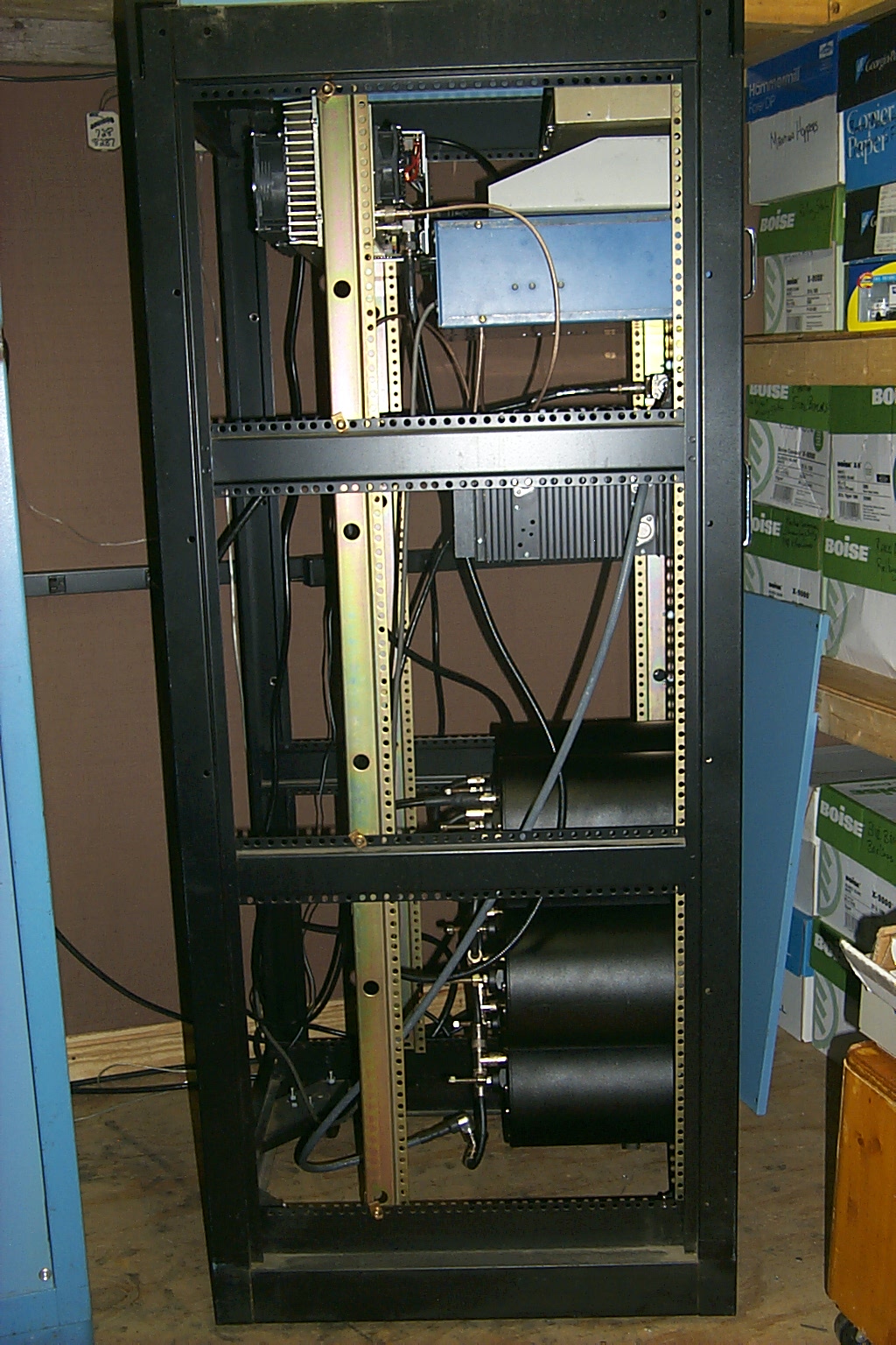
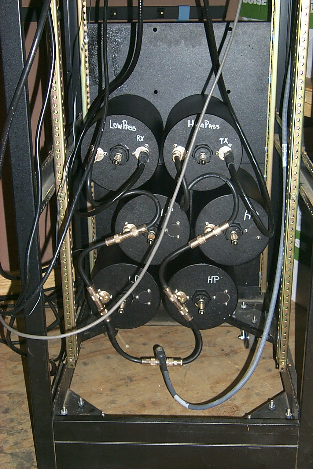
Even with the new temporary antenna online I was not happy with the repeaters performance so I decided to try and reconfigure the new cavities from Clay in the way we had done on the other repeater by moving both of the band pass cavities to the receiver path.
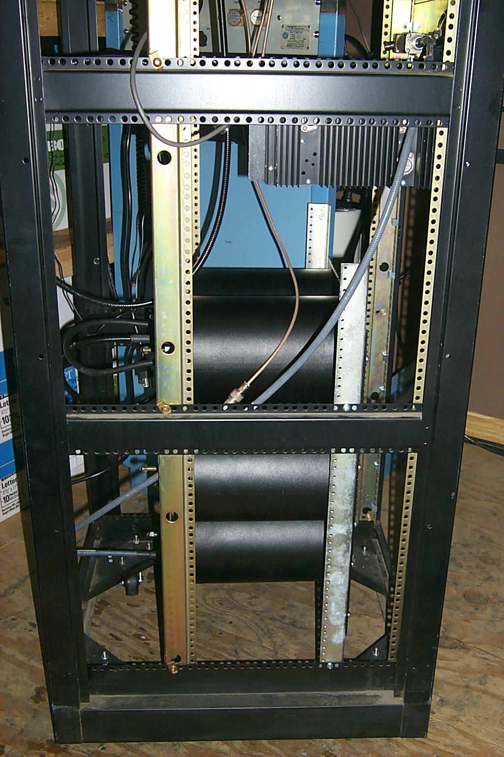
I ripped the Wacom cavities out of the rack and dragged them into the house to reconfigure the cables and retune everything. With the cavities out of the rack I decided to finally make a set of brackets to mount the duplexer inboard so the cover could be put back on the rack. When I had originally installed these new cavities from Clay last year I just mounted them in the front rails of the rack because that was quick and easy however I could not put the front cover back on the rack with the duplexer mounted in that location.
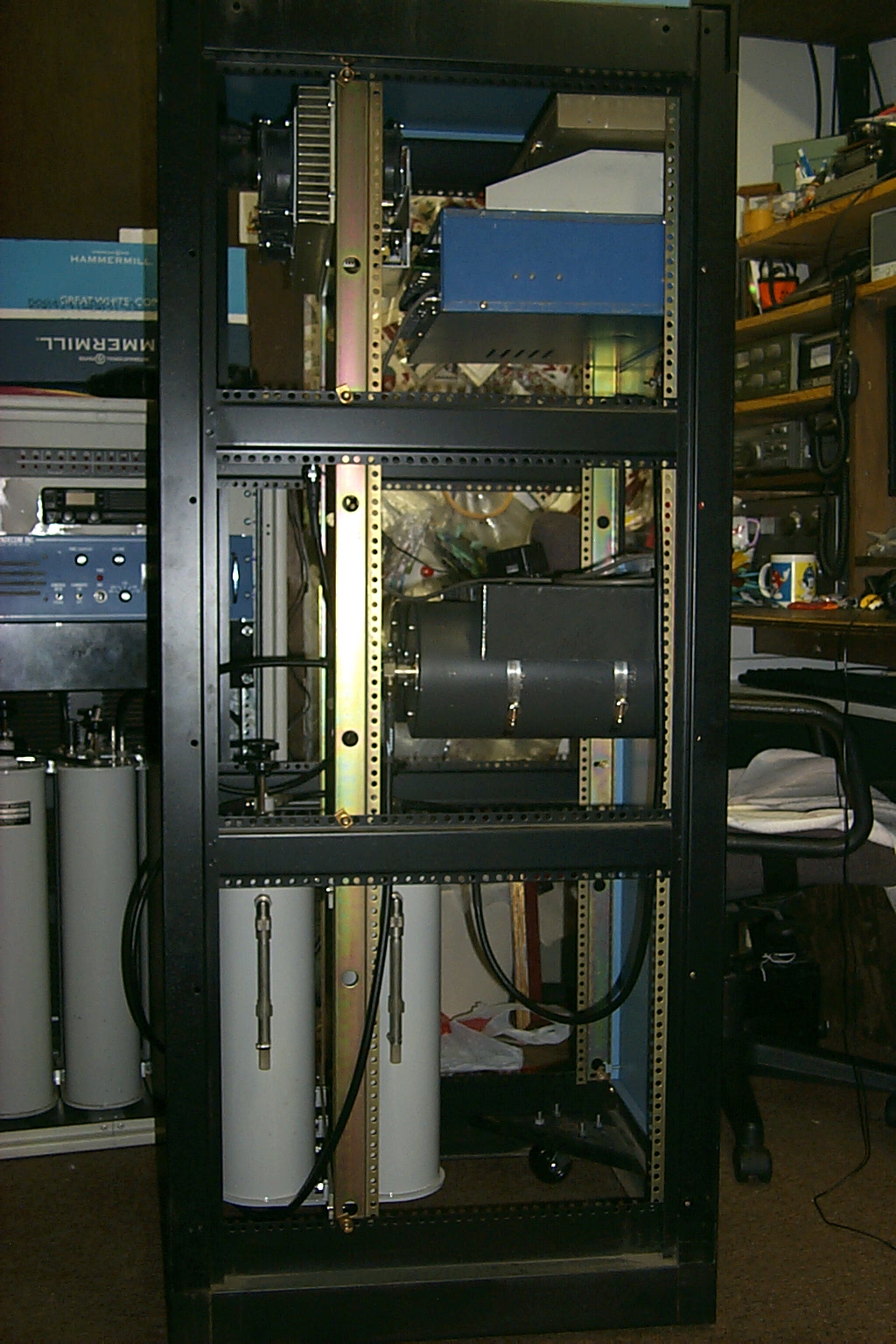
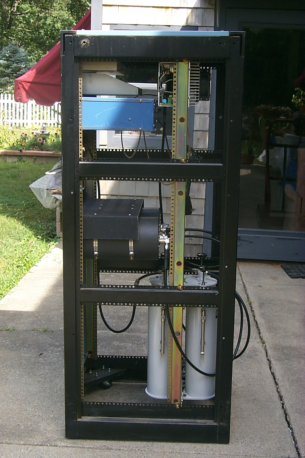
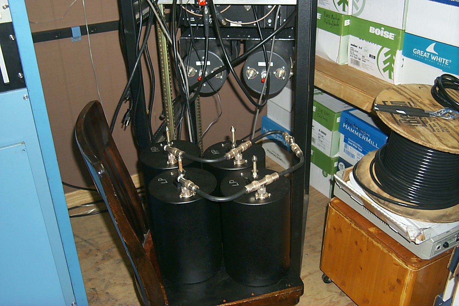
In these photos you can see the new mounting rails that I installed to hold the duplexer inboard the rack cabinet and the reconfigured cavities ready to be bolted back into the rack.
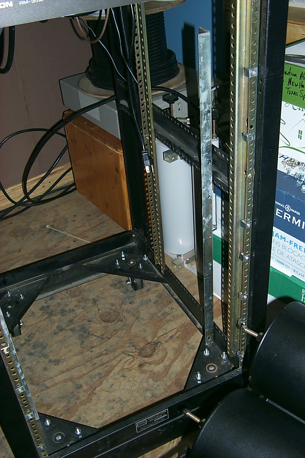
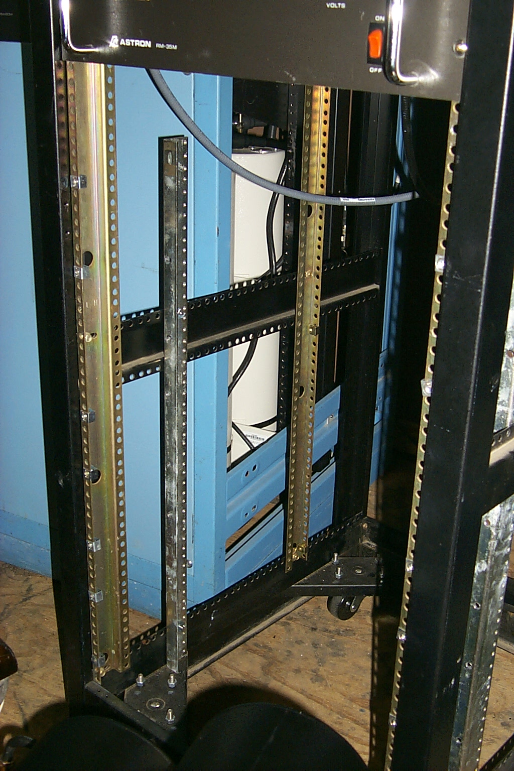
(click on images to enlarge)
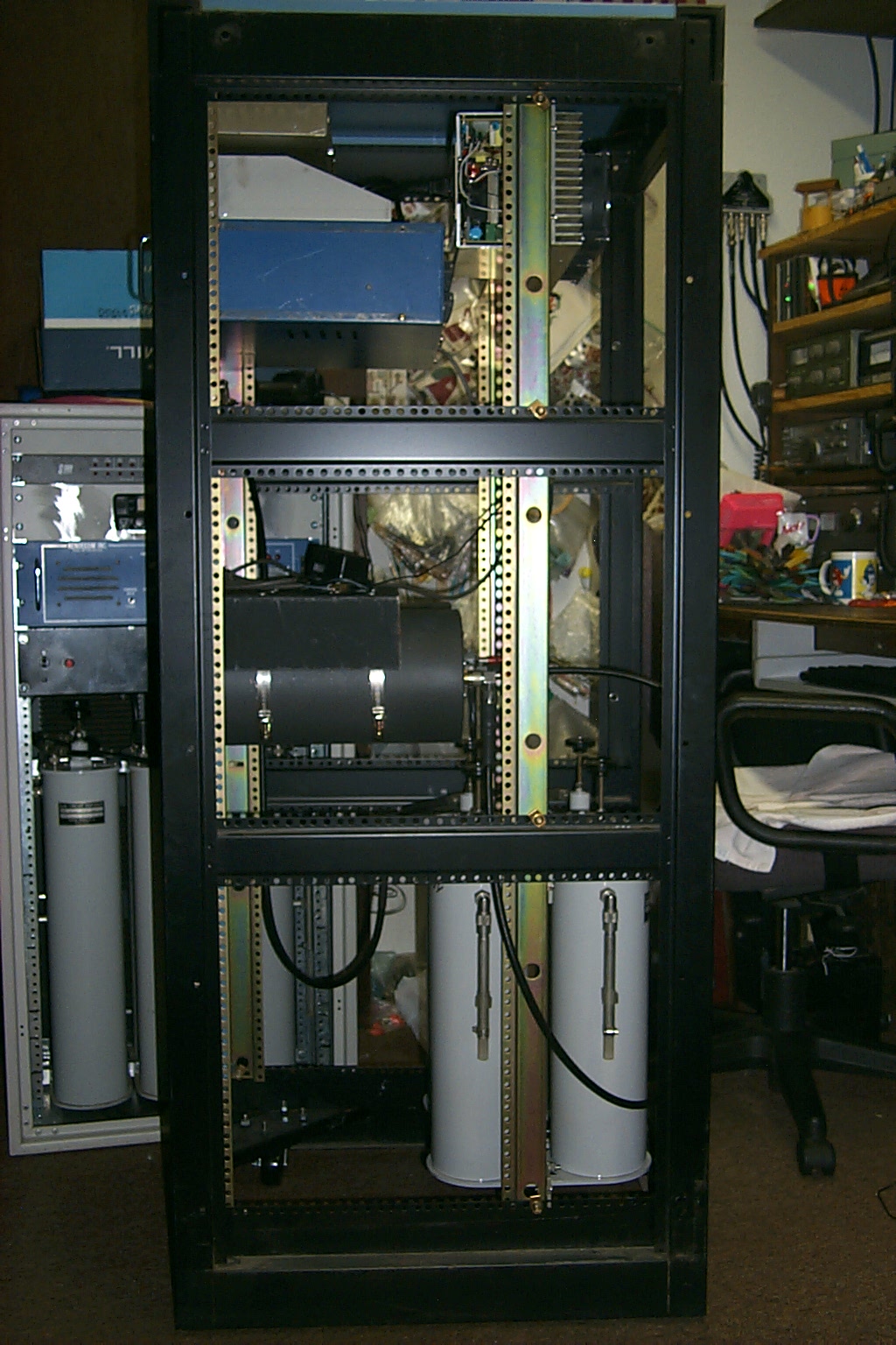
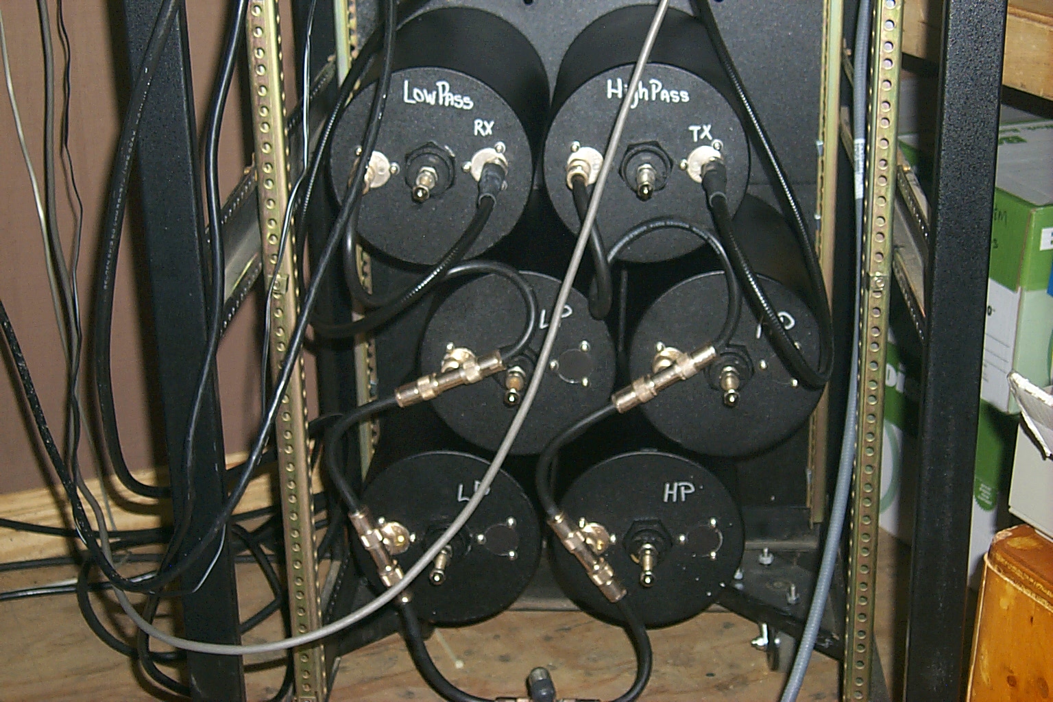
Here the duplexer is bolted back into the rack at the new location which will now allow me to install the front cover on the cabinet.
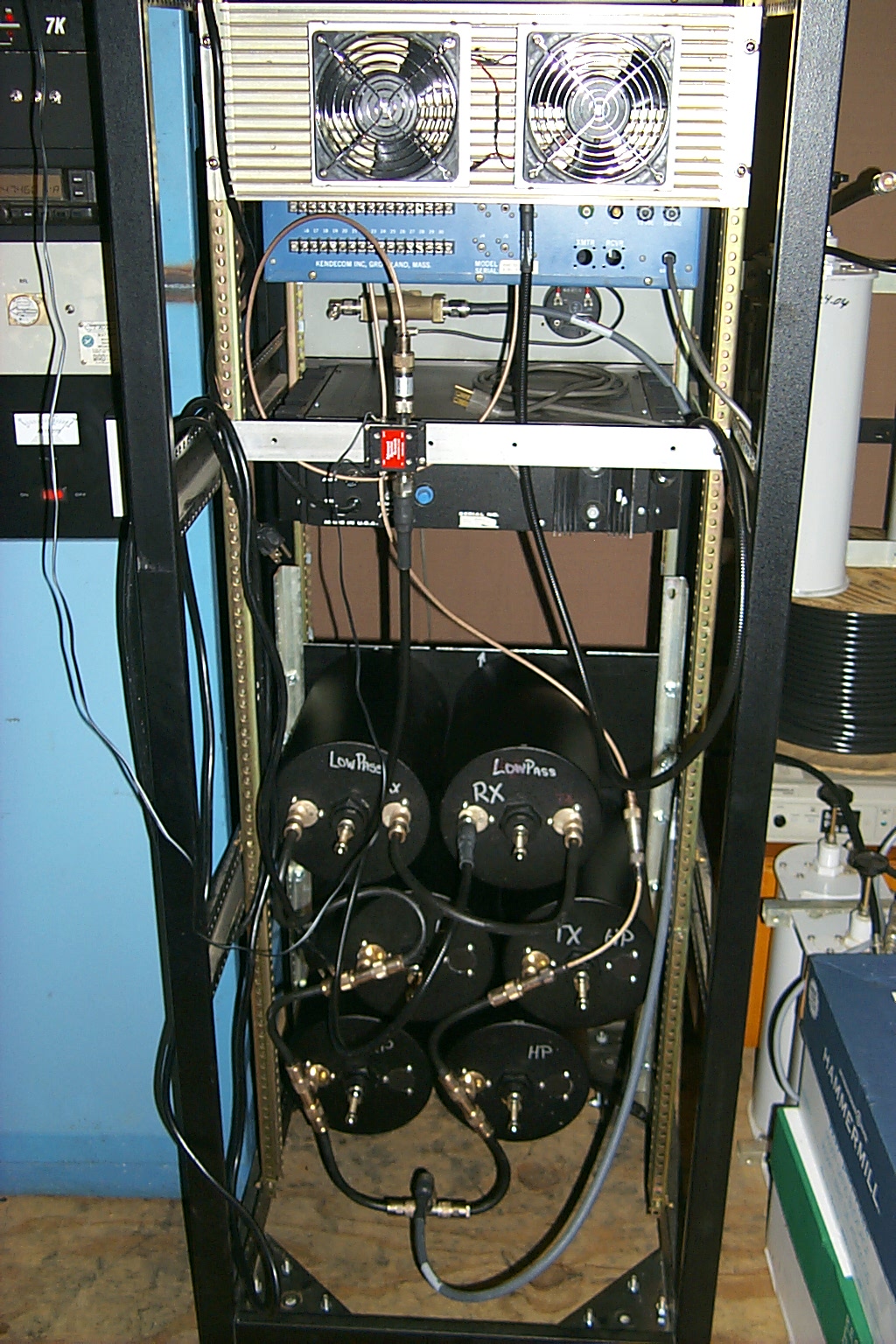
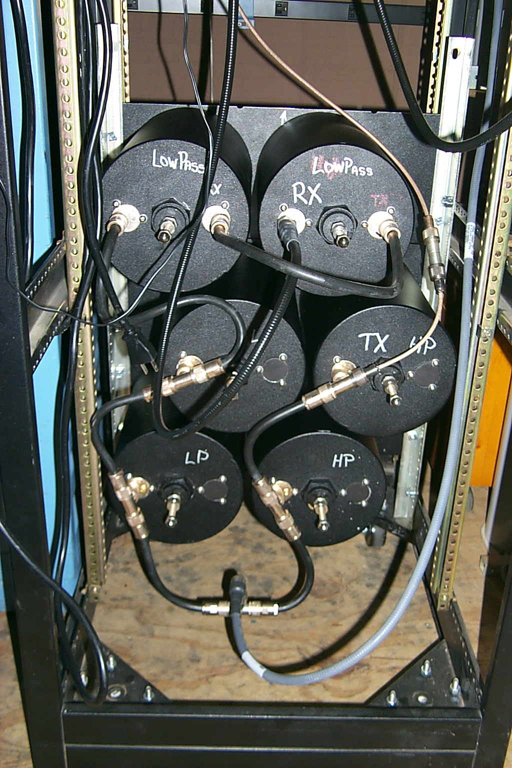
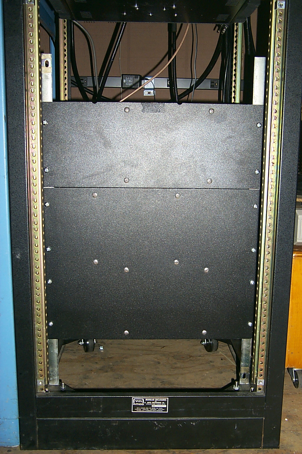
(click on images to enlarge)
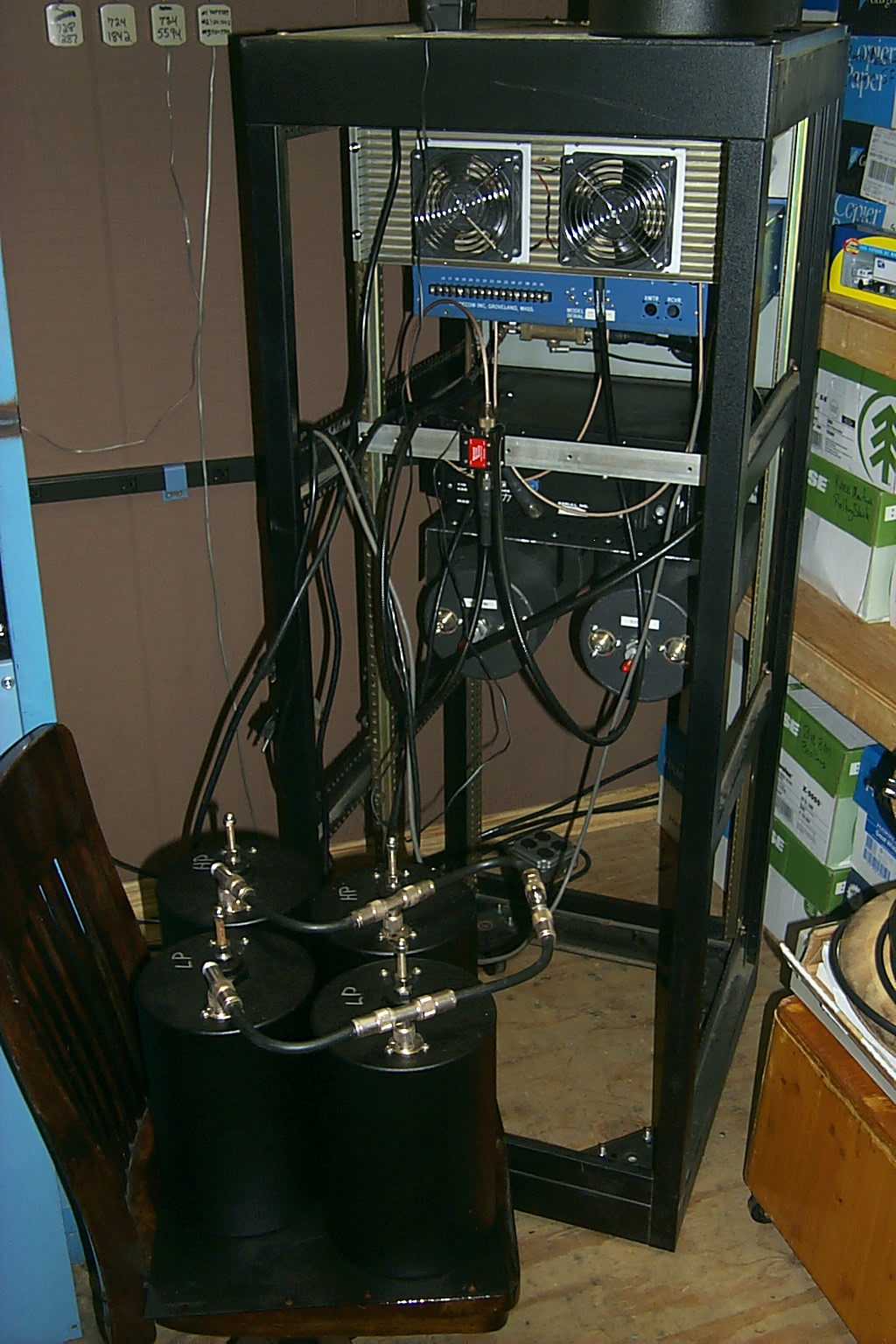
Everything all back together, the reconfigured cavities mounted in the new inboard location, the front cover back on the rack cabinet, and the repeater is also now running on the temporary antenna with good results / performance.

(click on images to enlarge)
Now I am thinking about adding one more cavity to the transmitter path...
...This crap never ends!
Update August 15th 2010
Duplexer Reconfiguration Part Two with visit to the HAMCOW
With the filter cavities in the new 2 x 4 configuration I was seeing much better receiver performance but there was a little desense from the transmitter. I decided to add a third cavity to the TX path for a new 3 x 4 configuration. I also pulled all of the coupling loops out of all the cavities and found that some had longer loops. I moved the longer loops to the receive cavities which are lower in frequency and the shorter loops to the transmit cavities.
(click on images to enlarge)
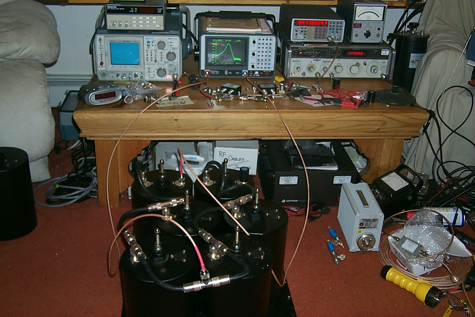
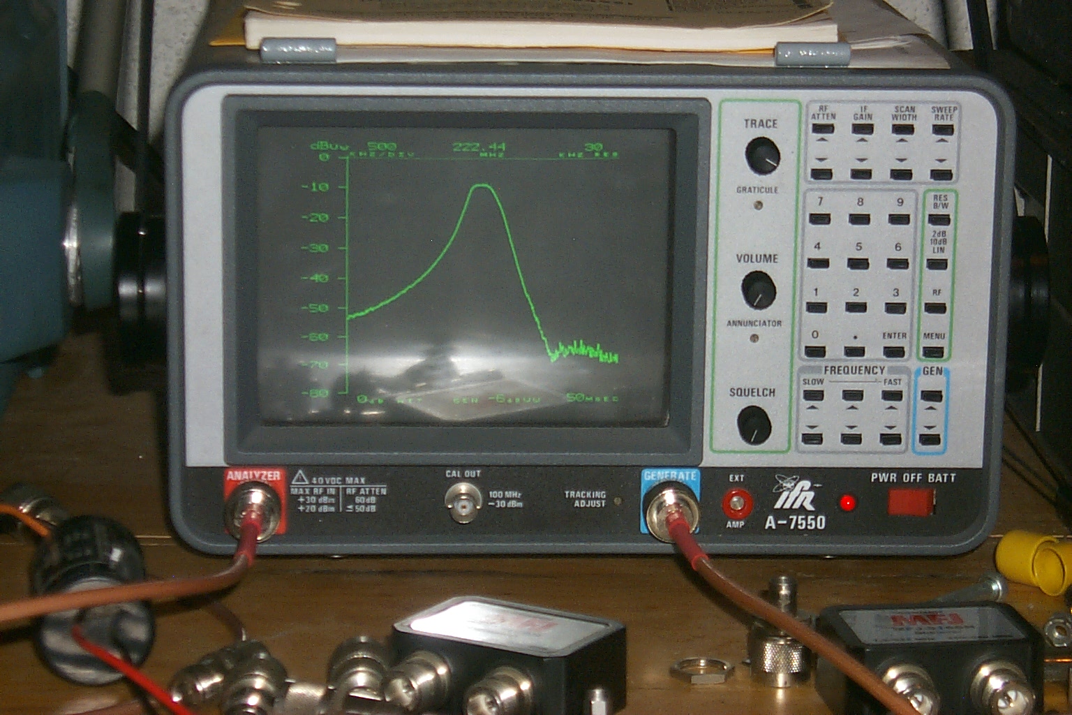
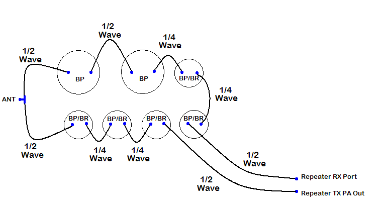
Once I had all the cavities tuned up in the new 3 x 4 configuration I dragged everything over to the HAMCOM to have Roland check out my tune-up job with his spectrum analyzer. Roland swept the duplexer and said...
"They are fine, don't touch anything."
This is a diagram of the new 3 x 4 duplexer configuration.

(click on images to enlarge)
Update November 15th 2010
The Lincoln 224.040 repeater was moved over to the new G7-220 antenna.
Finally after years of planning and waiting, and several months a hard work, the 224.040 repeater was moved from the temporary exposed dipole array to the new G7-220 at the very top of the repeater tower late in the afternoon on Sunday November 14th.
In this photo you can see the new Andrew LDF4-50B hard-line for the repeater antennas secured to the repeater shed and connected to the Polyphasers in the bulk-head.

(click on images to enlarge)
In this photo you can see the new repeater antennas and there location on the tower
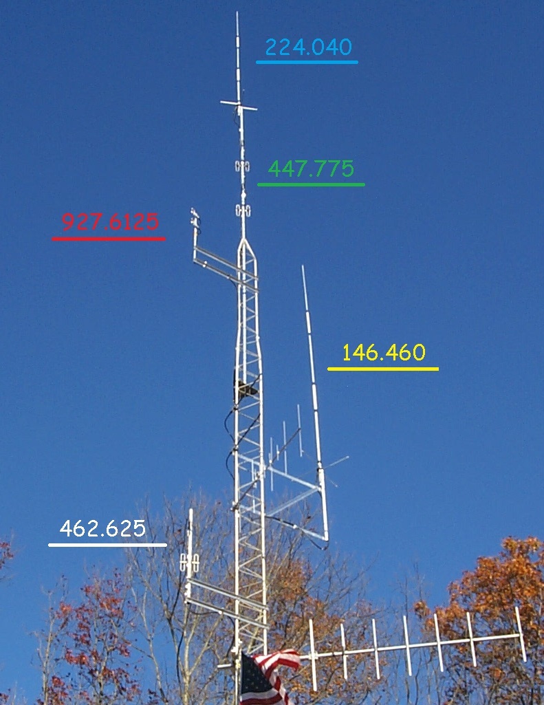
(click on images to enlarge)
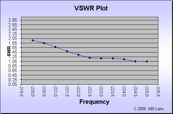
Here are the numbers from the VSWR sweep on the new antenna...
|
FREQ |
Watts Fwd |
Watts Rev |
VSWR |
|
220.00 |
30 |
3.2 |
1.97 |
|
220.50 |
29 |
2.6 |
1.85 |
|
221.00 |
28 |
1.8 |
1.68 |
|
221.50 |
25 |
1 |
1.50 |
|
222.00 |
23 |
0.49 |
1.34 |
|
222.50 |
23 |
0.22 |
1.22 |
|
223.00 |
24 |
0.18 |
1.19 |
|
223.50 |
25 |
0.18 |
1.19 |
|
224.00 |
25 |
0.11 |
1.14 |
|
224.50 |
24 |
0.02 |
1.06 |
|
225.00 |
24 |
0.015 |
1.05 |
Update 11/16/2010 - The signal is Monstrous!
The initial signal reports have been slowly coming in and the new antenna / hard-line combination are working better than I had expected. The repeater has reliable coverage to the north into MA about 20 miles, to the south about 20 miles, and to the east over 25 miles.
Unfortunately the external PA was having a problem with self-oscillation and was sending spurious emissions out across the 220 MHz band so I pulled it out of the rack. As always the service from Henry is outstanding and a new replacement PA should be here soon...
Update December 4th 2010
Rebuild Henry power amplifier goes back on the air!
The newly rebuilt, 13.8
volt – 100 watt, Henry power amplifier was placed back into service today at
12:30 PM.
I made several measurements before
mounting the new PA back in the rack cabinet to make sure I knew what the change
in power would be. For the past two weeks while I was running on just the
repeaters transmitter (no power attenuator inline) 224.040 had 12 to 15 watts
out of the duplexer depending on which of my elements I used.
In this new configuration with the
rebuilt PA and a 3dB power attenuator inline between the repeater transmitter
and the PA 224.040 has 50 to 55 watts out of the duplexer. I am going to leave
the repeater running in this configuration for the next few days / weeks to get
a feel for how the coverage will be running at 55 watts.
If the receiver sensitivity is still
good and out performing the repeaters talk out power, I can remove the 3 dB
power attenuator and bring the power up to 100 watts or so…(High Power)
Henry PA Back inline 12/04/2010 - 55w FWD / 0.08 REF / VSWR =
1.08
Update May 25th 2011
The 3dB power attenuator has been removed...
After six months of testing at the medium power level I have decided to remove the 3dB power attenuator and see how the repeater would perform are the higher power.
The initial reports the last few days since removing the power attenuator have been positive and there does not seem to be any issues with the receiver sensitivity.
05/25/2011 - 70w FWD / 0.125 REF / VSWR = 1.09:1
The next step will be to upgrade the firmware in the Scom 7k controller and wire up the new TK-830 UHF link radio...
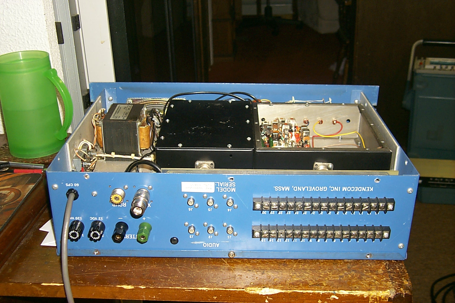
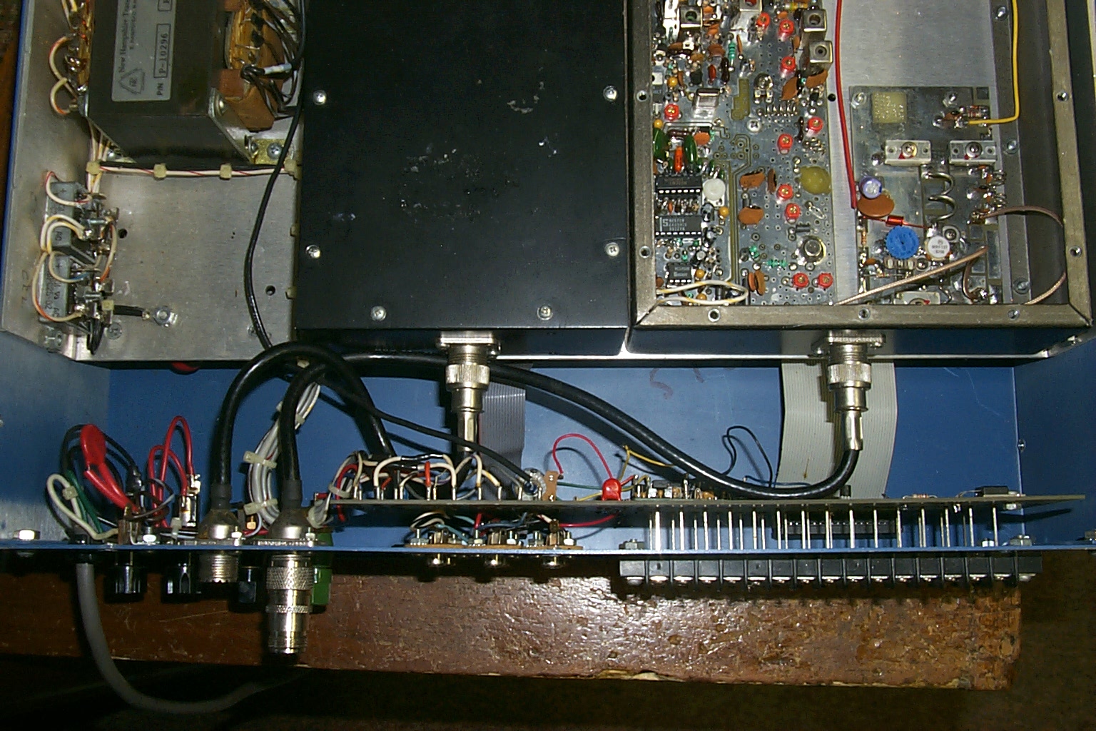
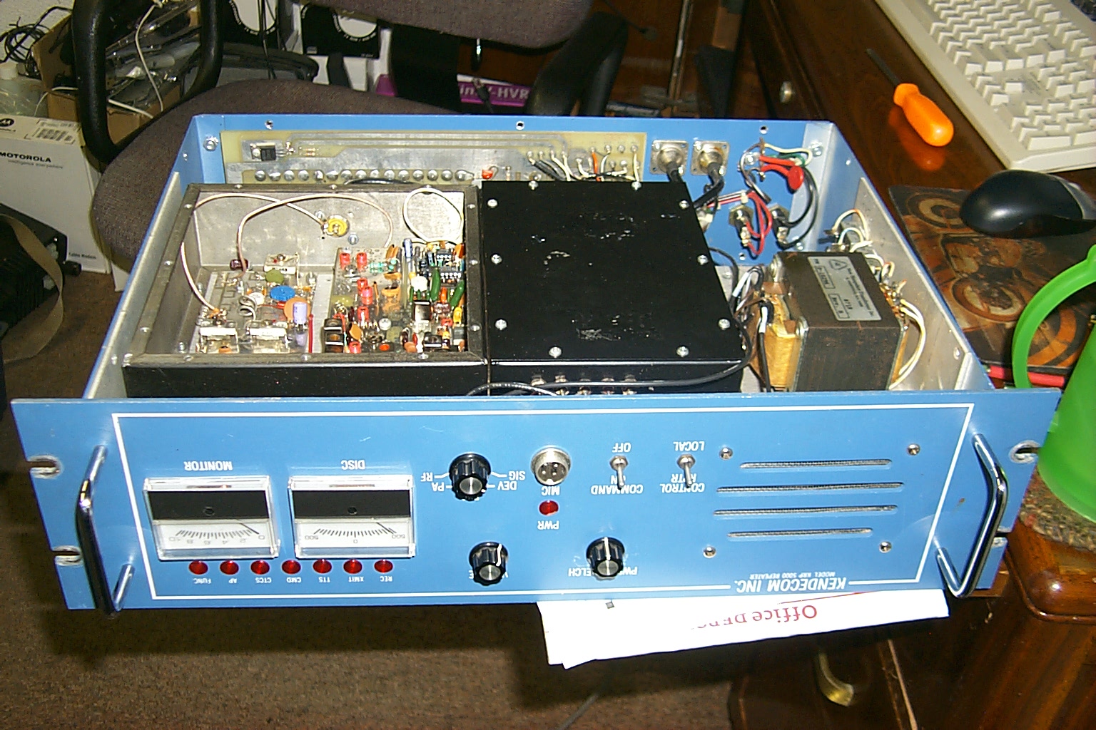
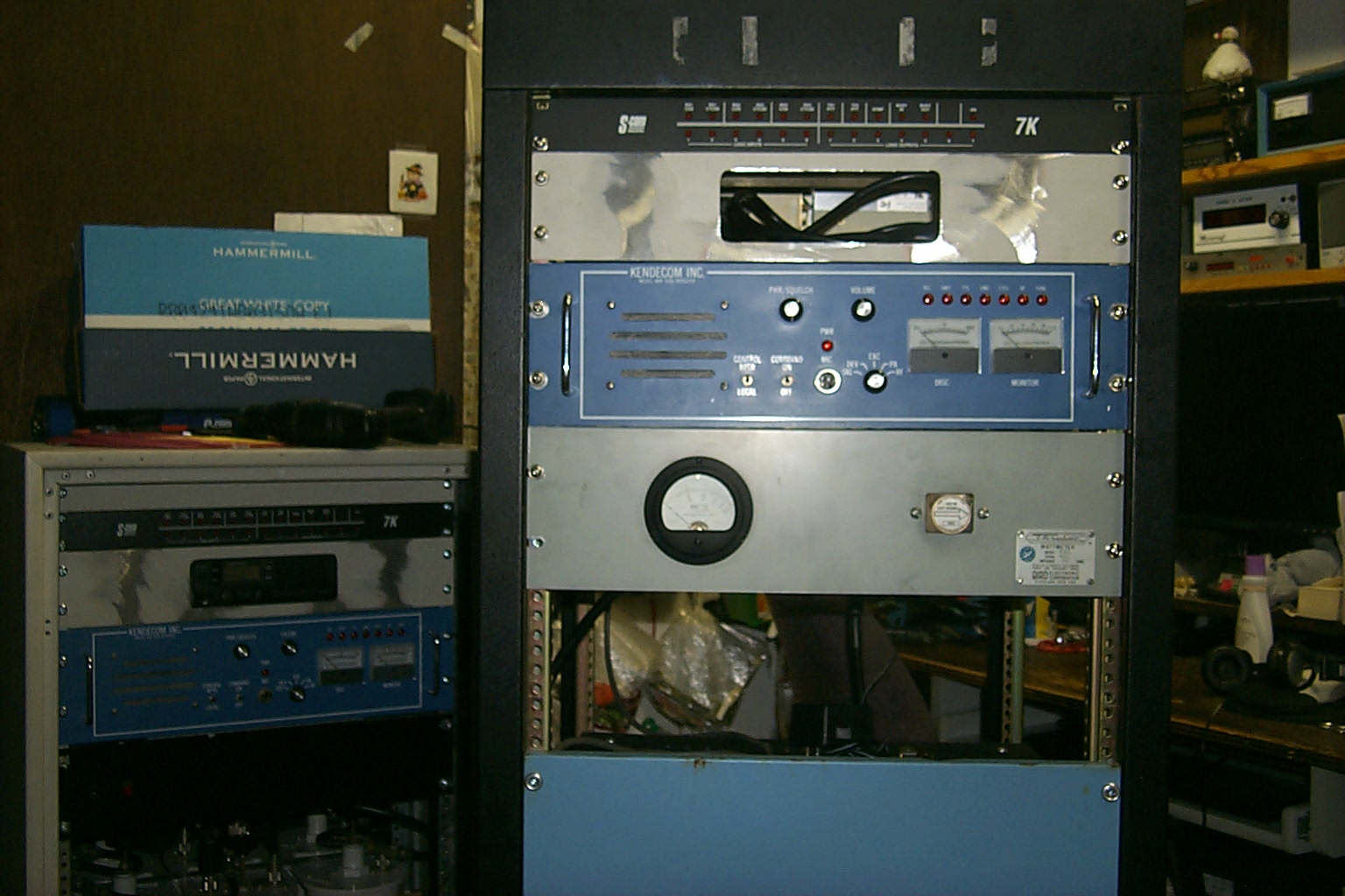
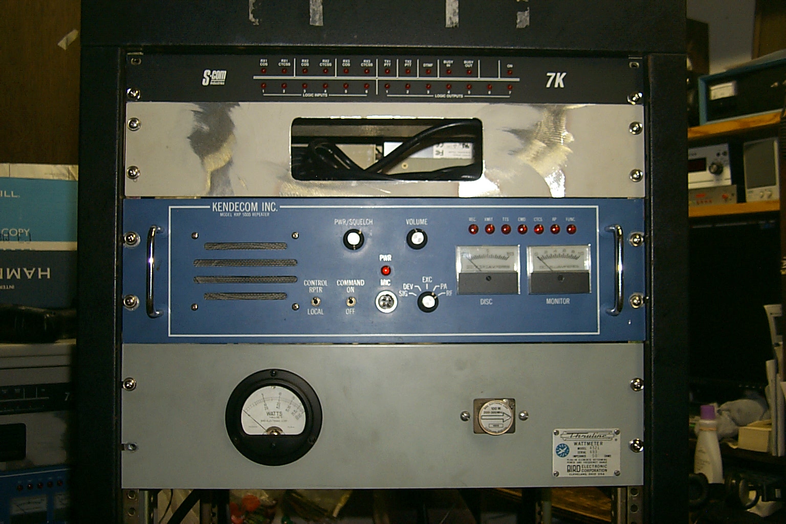
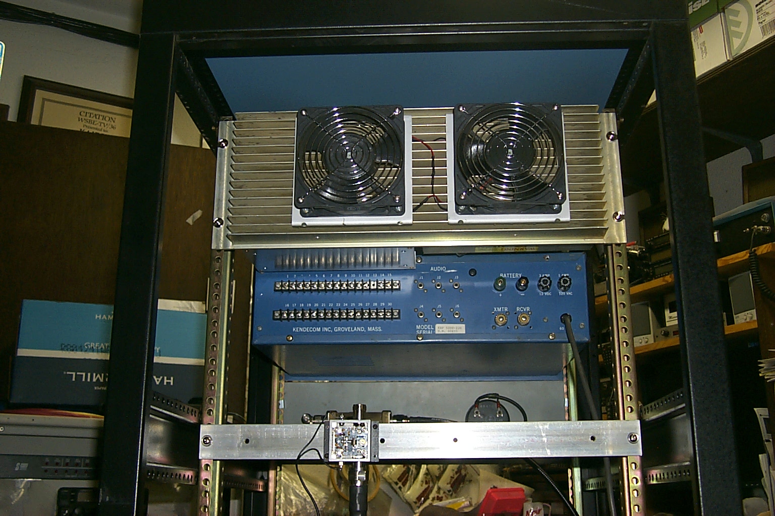
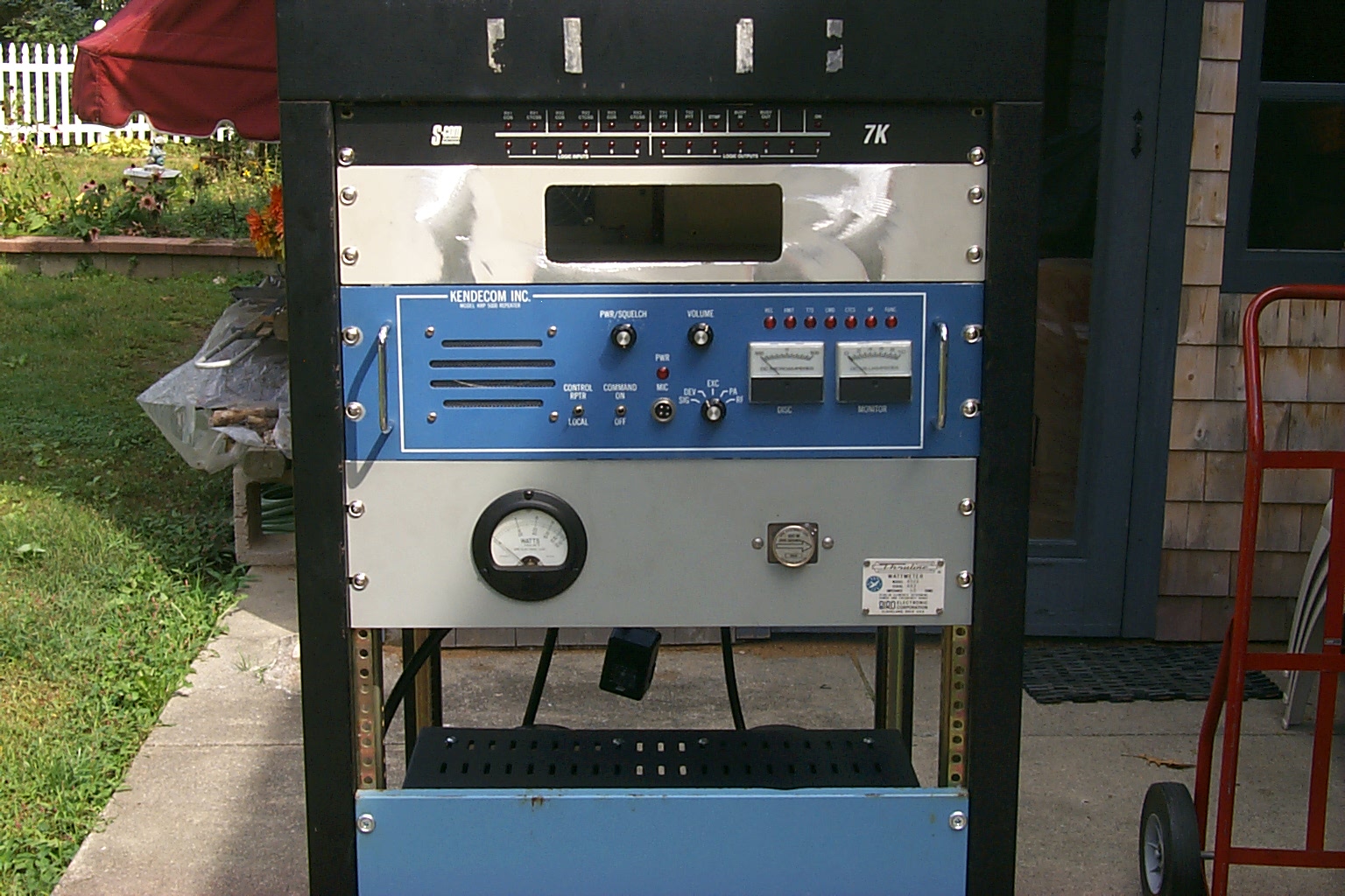
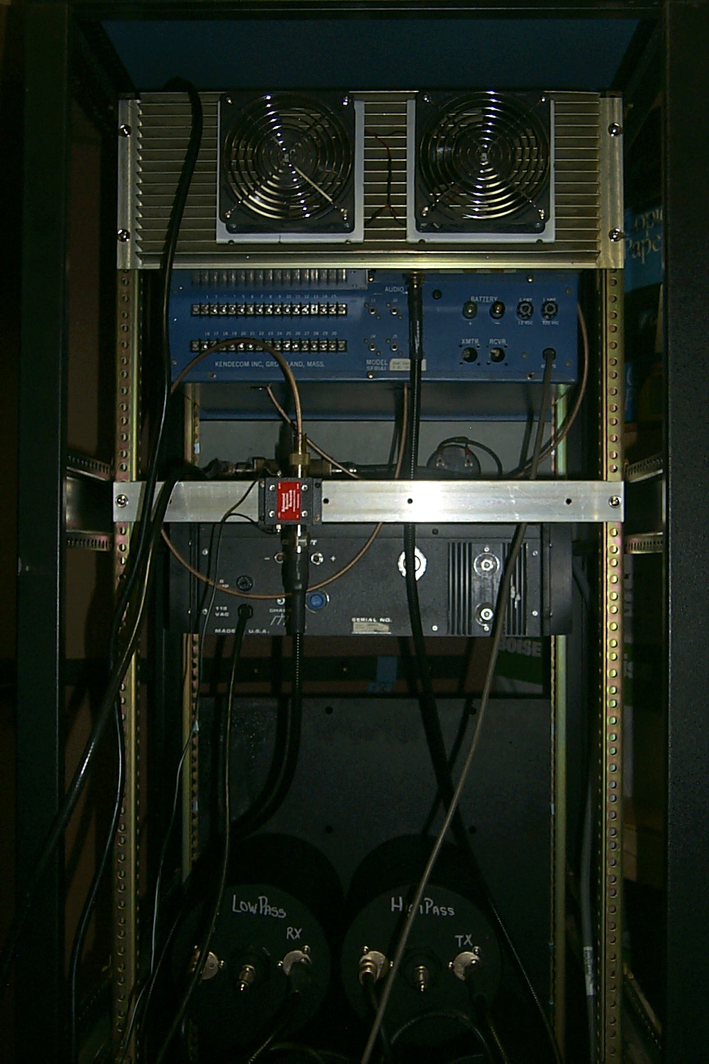
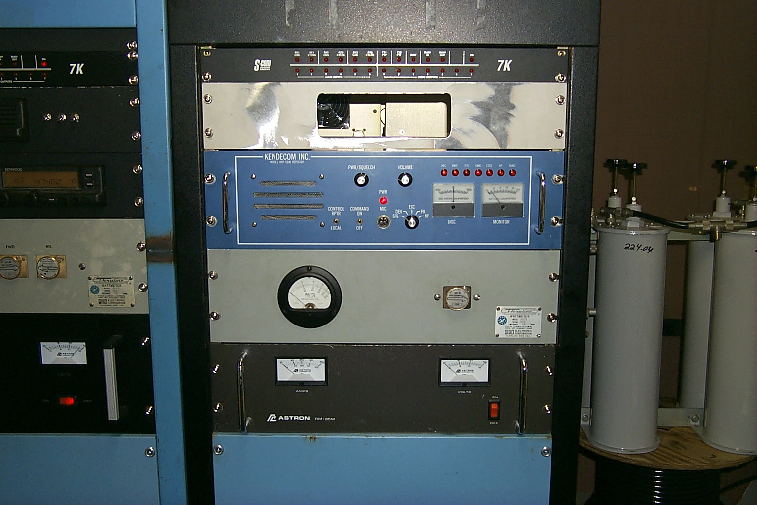
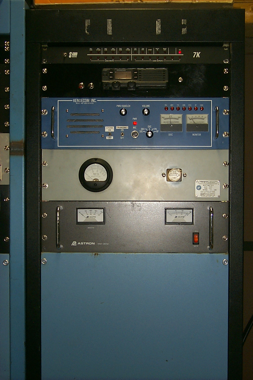
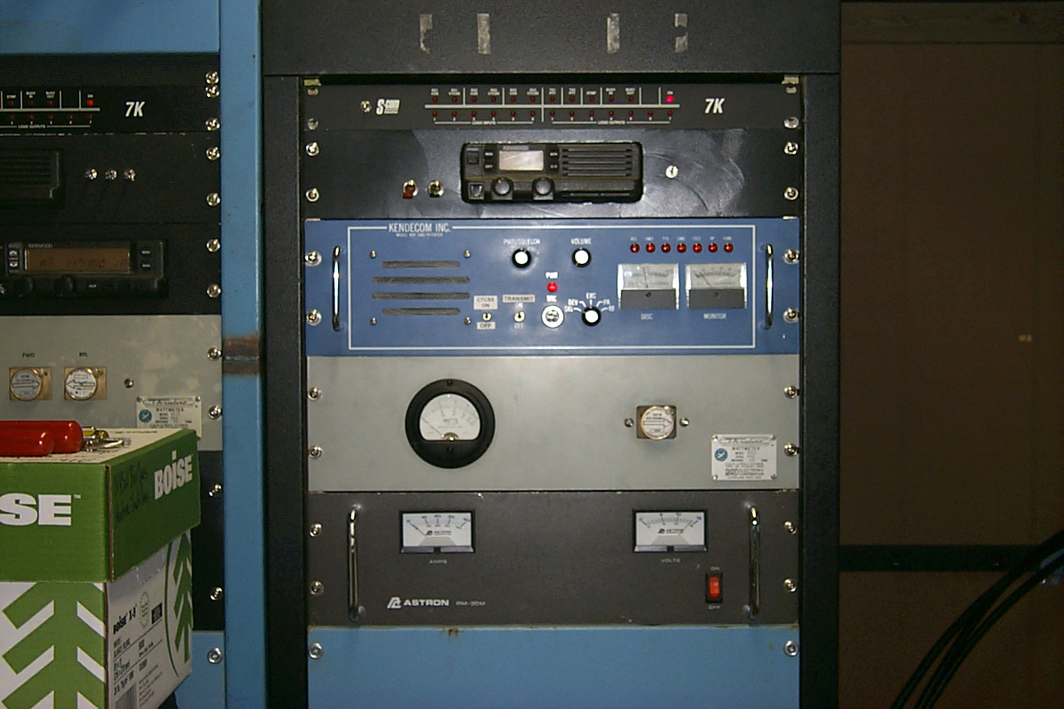
In these photos you can see the rebuilt Kendecom, I had Gary up at ACS in Groveland, MA go through everything. He replaced some dried out capacitors in the receiver and installed all of the upgrades to the repeater brining it up to date with the current version.
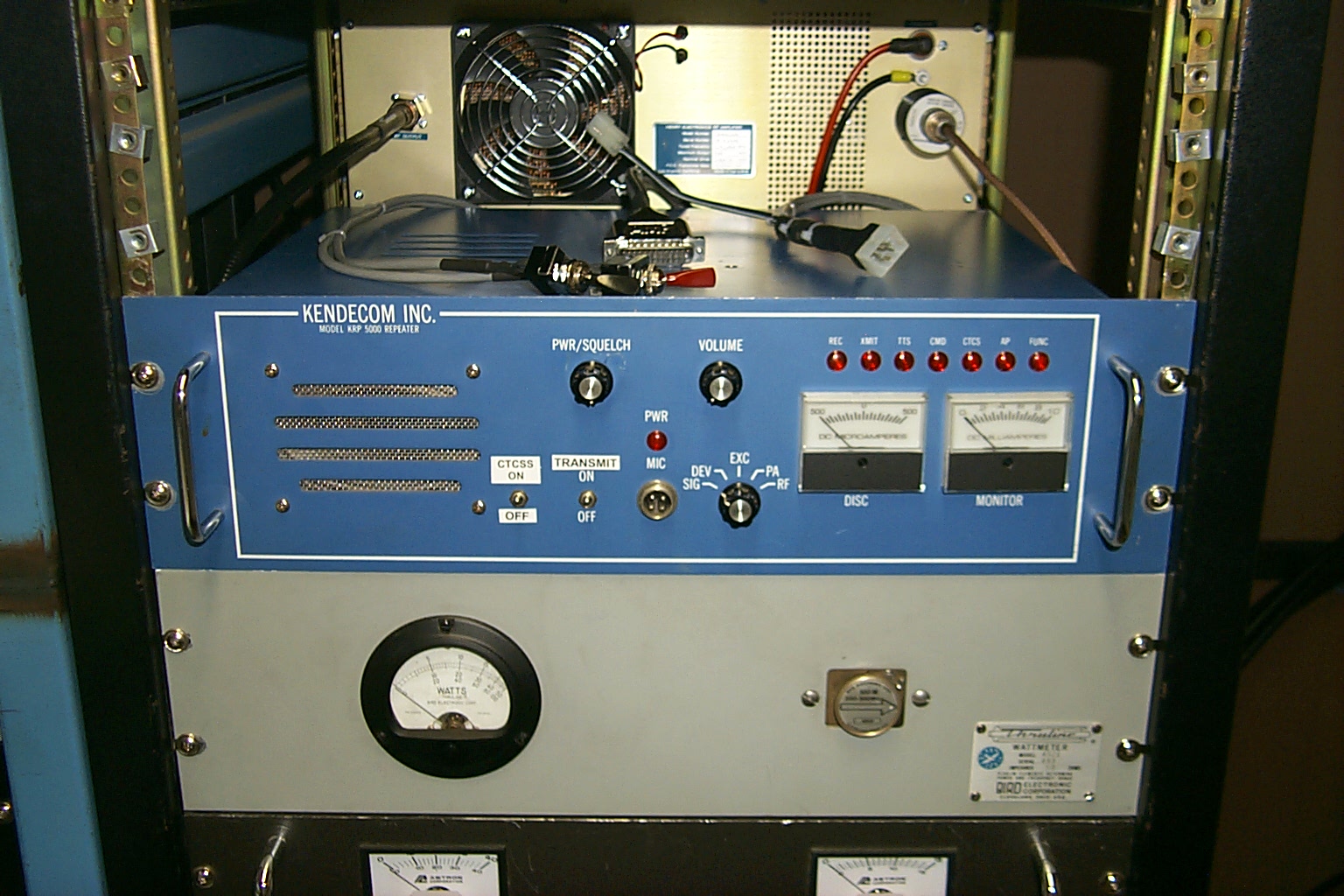
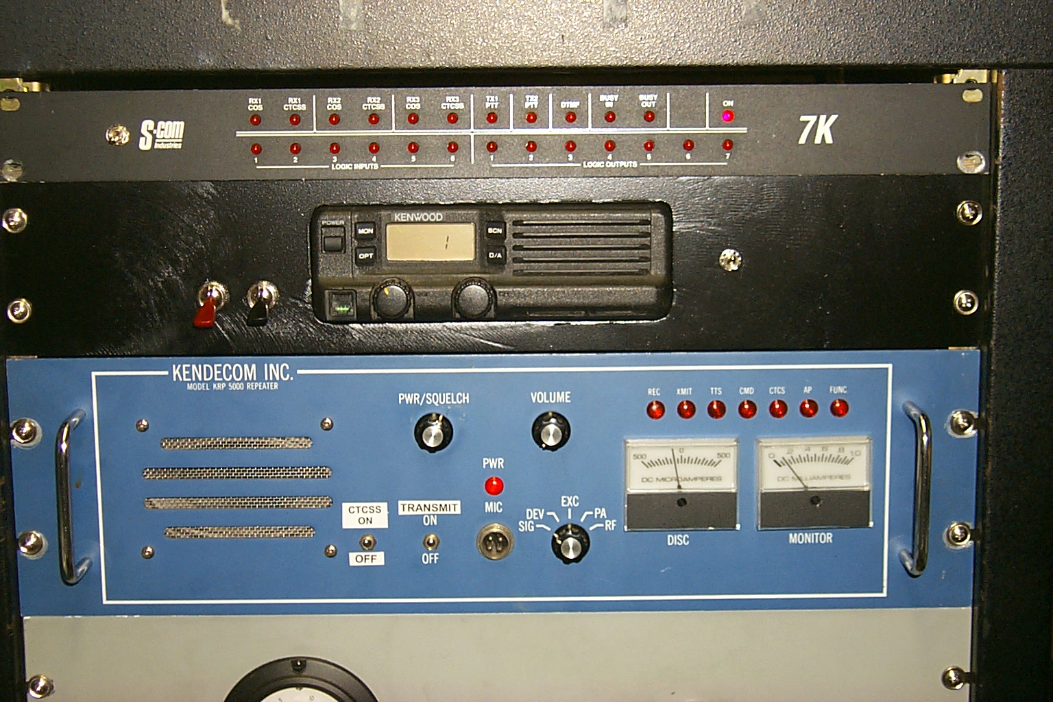
(click on images to enlarge)
Once I had the repeater back from Gary I wired up the SCOM 7k controller and Kenwood TK-830 UGHF link radio. With the external controller and link radio online the Lincoln 224.040 repeater could be tied into the network with a simple touch tone command.
KaBoom
Update February 25th 2012
The rebuild Henry power amplifier blew up this morning!
The moment I walked into the repeater vault I could smell that something had burned. I pulled the PA out of the rack cabinet, packed it up, and shipped it back to Henry Radio for repairs...
Update March 23rd 2012
As always the support from Henry Radio was awesome, I shipped the blown PA back for repairs and Ted took care of everything for me. Several days later I had a rebuild PA back online and working perfectly.
After talking with Ted we believe that I was driving the PA too hard after removing the power attenuator back in May of 2011 so I decided to install another band pass filter cavity between the repeaters transmitter and the Henry PA, this would allow me to fine tune the insertion loss of the filter cavity to reduce the drive into the power amplifier.
I made a few measurements while
installing the new band-pass cavity. The Kendecom transmitter power is 26.5
watts into a dummy load, with the 3 dB power attenuator inline the power is 14
watts, and with the new band-pass cavity inline the power is 15 watts.
With the new band-pass filter cavity inline the 15 watts from the Kendecom repeater is driving the Henry PA output power to 90 watts now, 10 watts below the rated 100 watts for 100% duty cycle, so hopefully it will play for a long time now without burning up in extended repeater duty.
My Bird 4410 meter was reading 90 watts forward power with 3 watts reflected power for a VSWR of 1.45 : 1 measured at the output of the Henry PA to the input of the duplexer.
While I was in the repeater shed doing
some testing… A station that had a less than full quieting signal (good copy
with some white noise) made a long transmission while I cycled the repeaters
transmitter on and off several time. I was watching the signal meter on the
front of the repeater reading the input to the receiver and listening to the
local receiver speaker while turning the transmitter on and off and it made
absolutely NO difference to the signal coming into the receiver that was
detected by the meter or my ear.
Few more tweaks needed June 2012
This repeater rebuild it still ongoing and the page is currently...

Return to the KA1RCI Repeater Network Home Page
This page was last updated on 03/06/2014.
Send mail to [email protected] with questions or comments about this web site.
Copyright 1995-2012 Steven M Hodell
Copyright in these pages, in the screens displaying the pages and in the information, materials and other content contained in this web site is owned by Steven M Hodell unless other wise indicated and is protected by U.S. and international copyright laws and treaties. The information, materials and other content of this web site may not be copied, displayed, distributed, downloaded, licensed, modified, published, reposted, reproduced, reused, sold, transmitted, used to create a derivative work, or otherwise used for public or commercial purposes without express written consent.