146.985 / 146.385 with PL 67.0
Exeter - Rhode Island
Trustee / Sponsor K1DA
Chucks 146.985 repeater had been off the air due to problems with the hardware. After talking with the boys I asked if they would like me to build a new repeater for that frequency pair / "south zone" site while Joe was building the new .985 system. I already had most of the components need in my spare parts pile and was about to build a new 2 meter repeater for one of my southern RI sites anyway.
146.985 / 146.385 New Repeater 2004
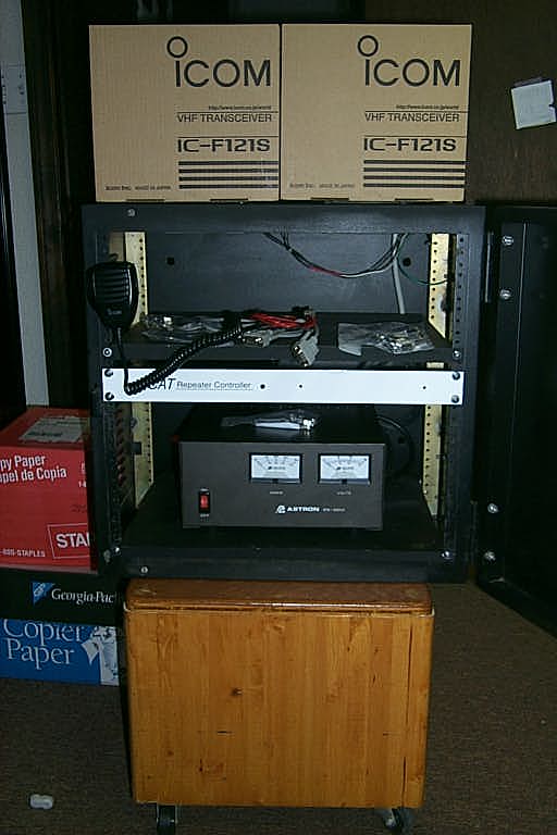
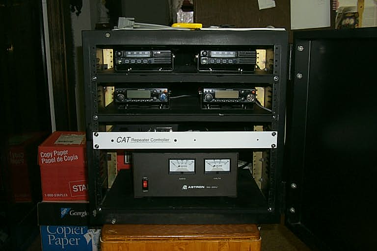
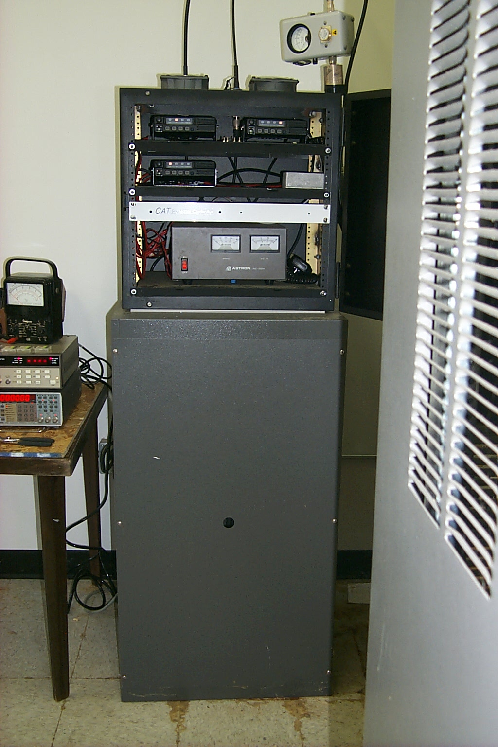
Starting with the cabinet and 35 Amp power supply from the Packet Radio node I purchased a new CAT-200B controller and another set of commercial RF units I had just deployed on my 146.460 and 447.775 repeaters. I built this new repeater as a temporary 146.985 system for the "south zone" which will be moved to another site once Joe has completed building the new .985 repeater.
(click on images to enlarge)
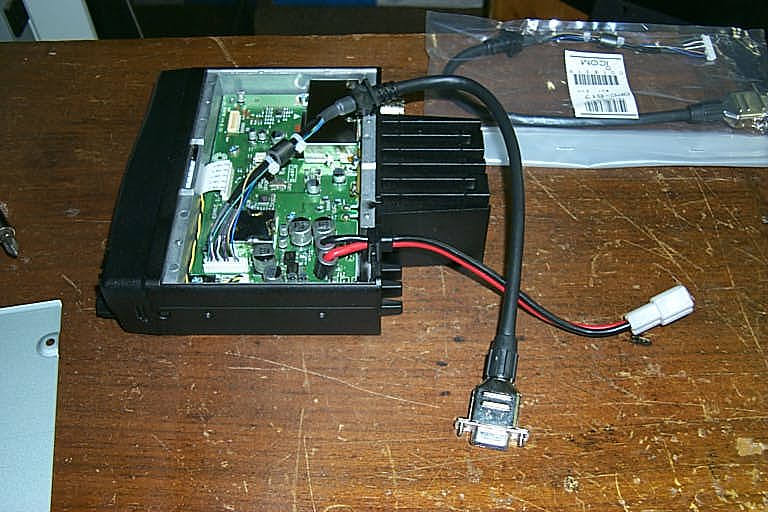
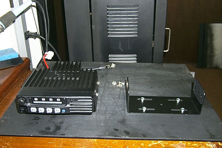
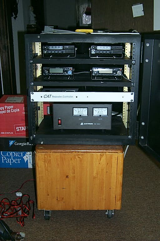
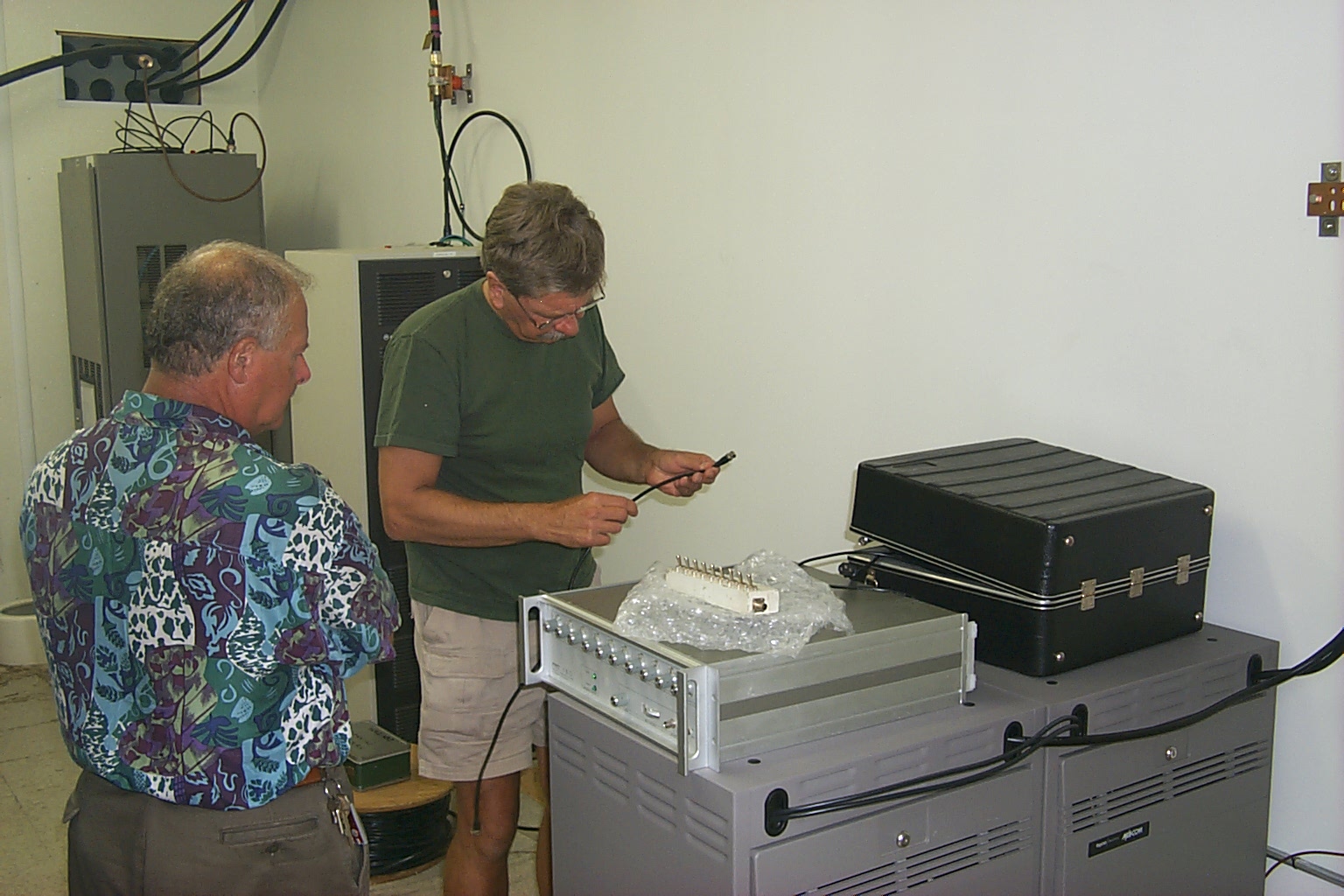
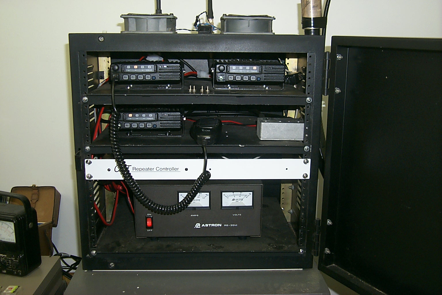
The matching IC-F121S Mil-spec radios provide the RX and TX for the 146.985/146.385 repeater pair. Icom makes a optional cable assembly that brings all the necessary control signals to a DB-9 connector making the connection to the repeater controller very easy. I have also installed Kenwood 220 and 440 link radios for access to my other voice repeaters at sites in Providence and Johnston.
(click on images to enlarge)
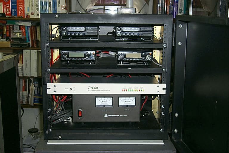
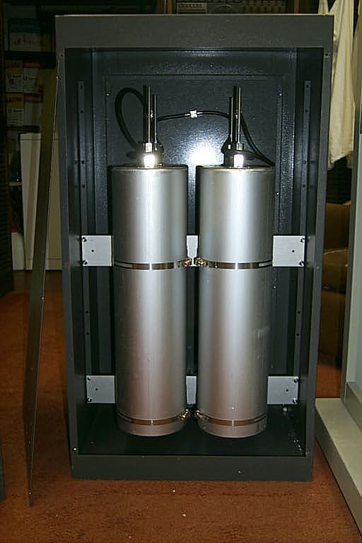
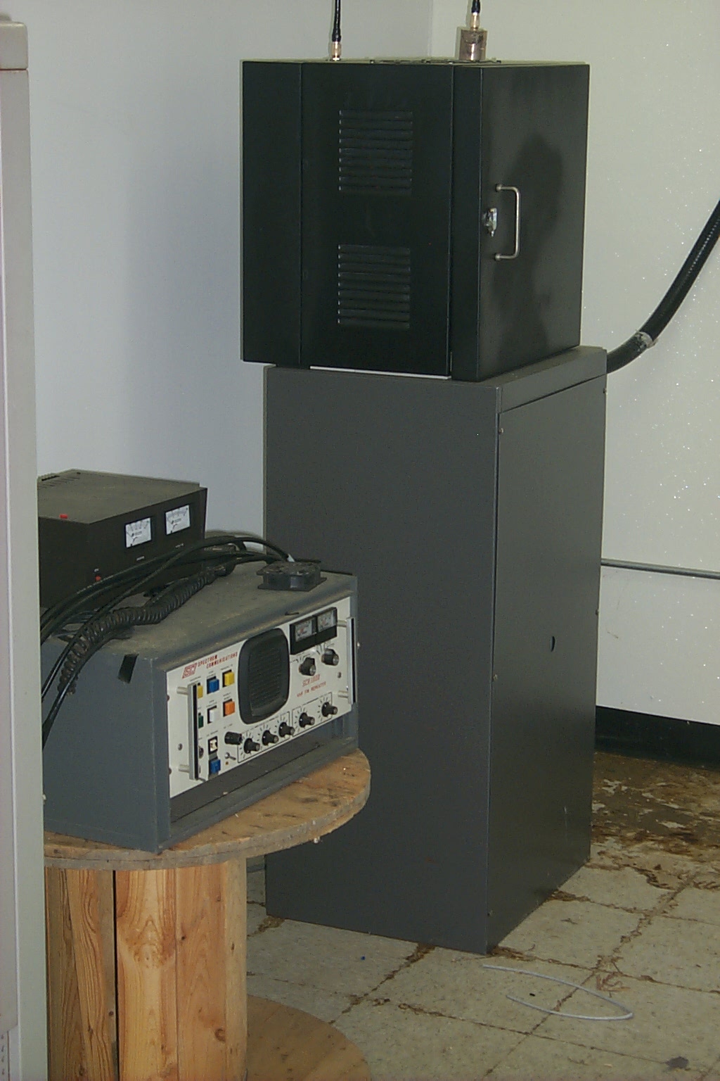
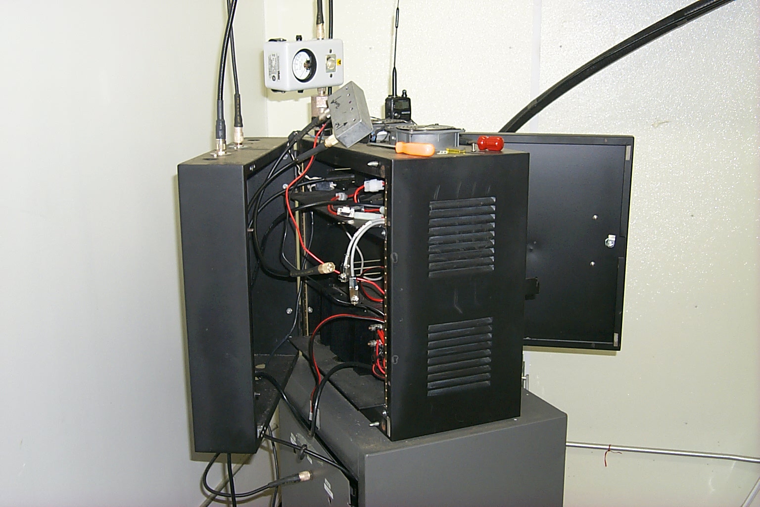
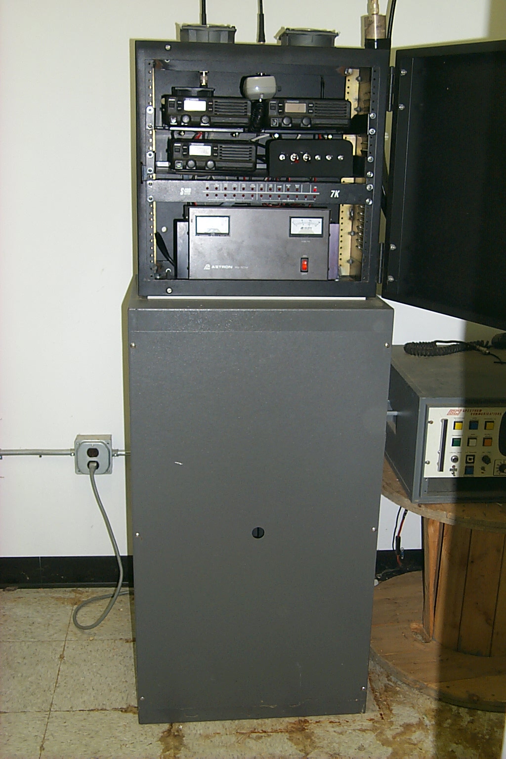
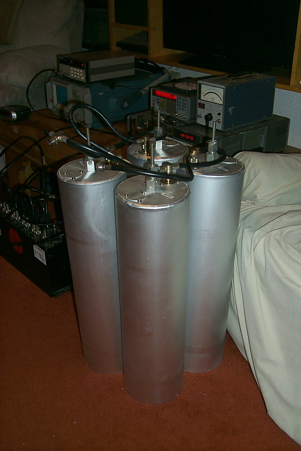
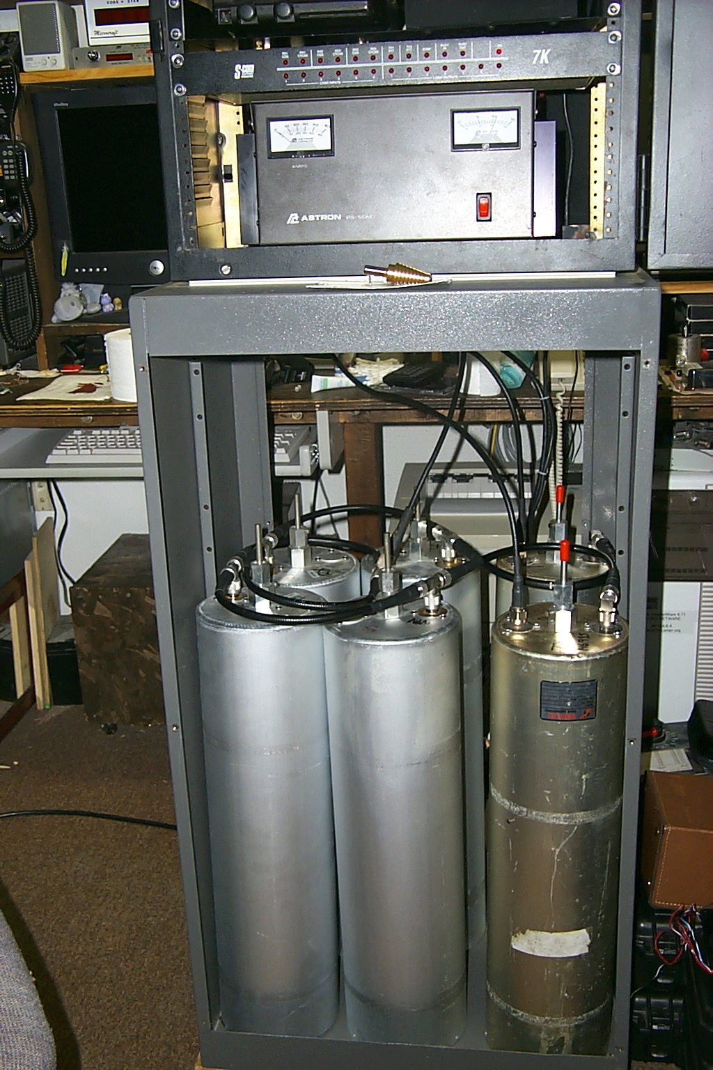
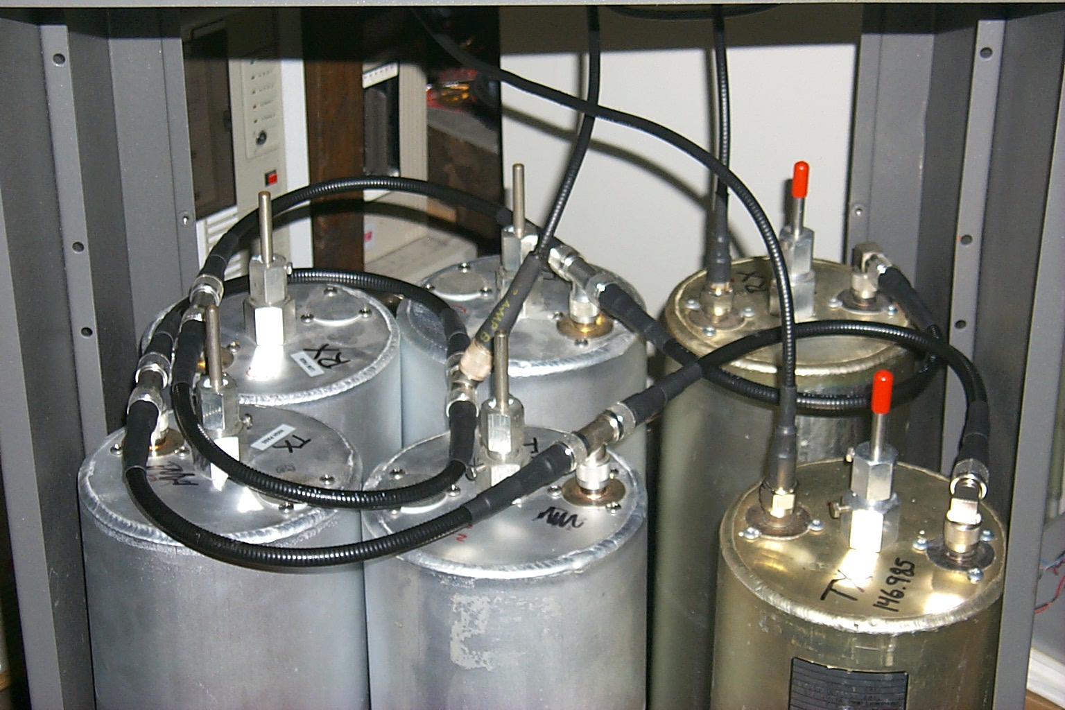
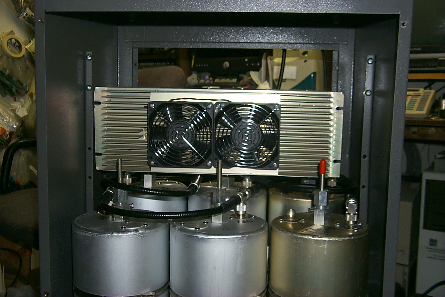
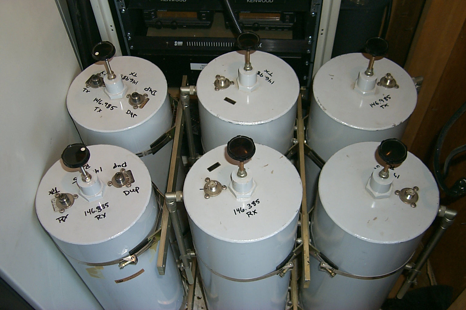
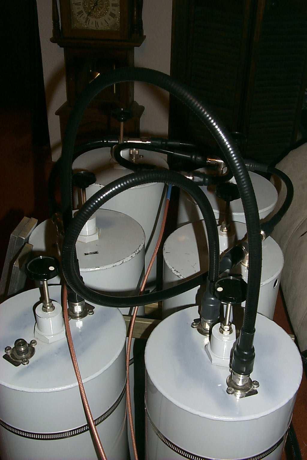
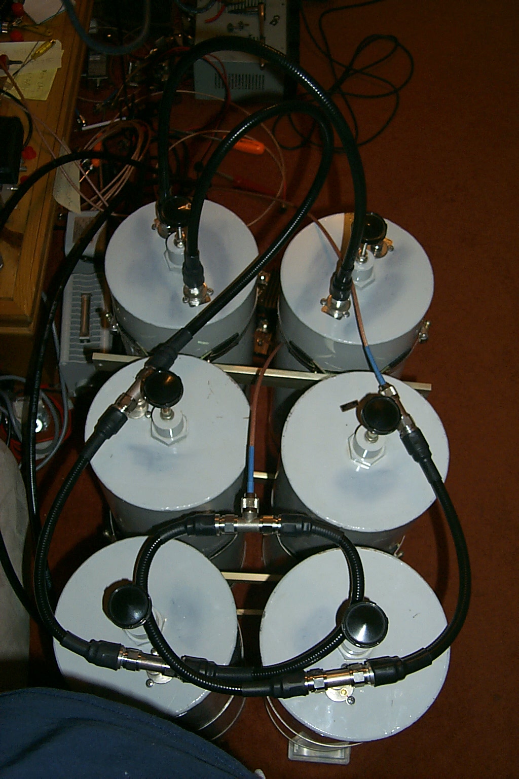
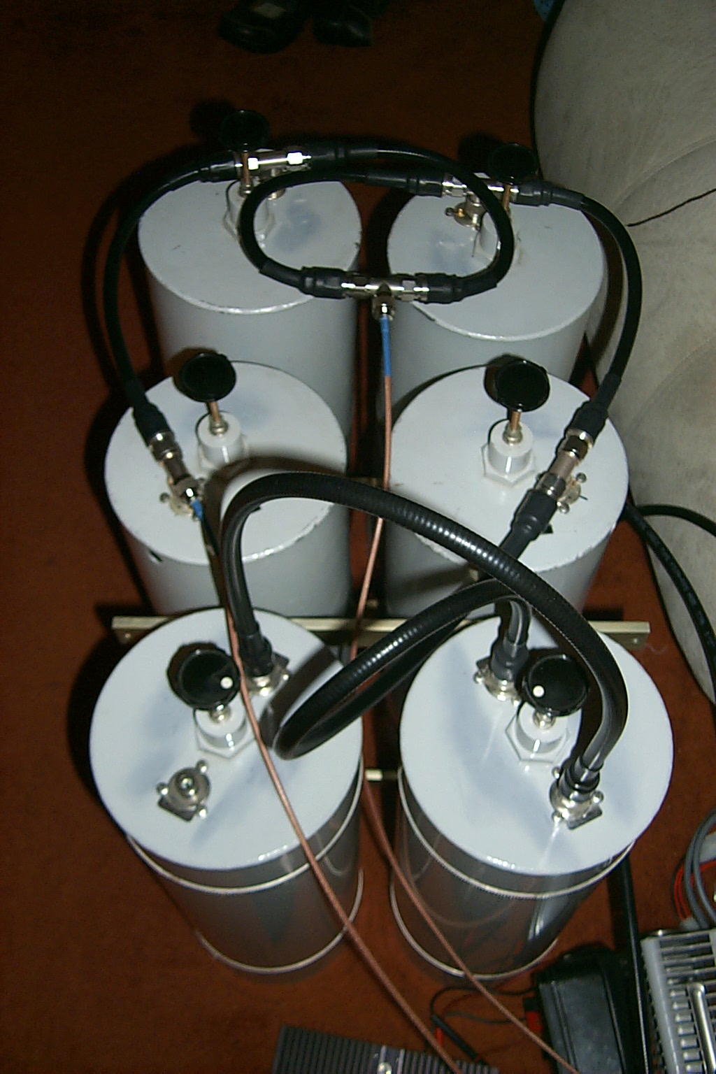
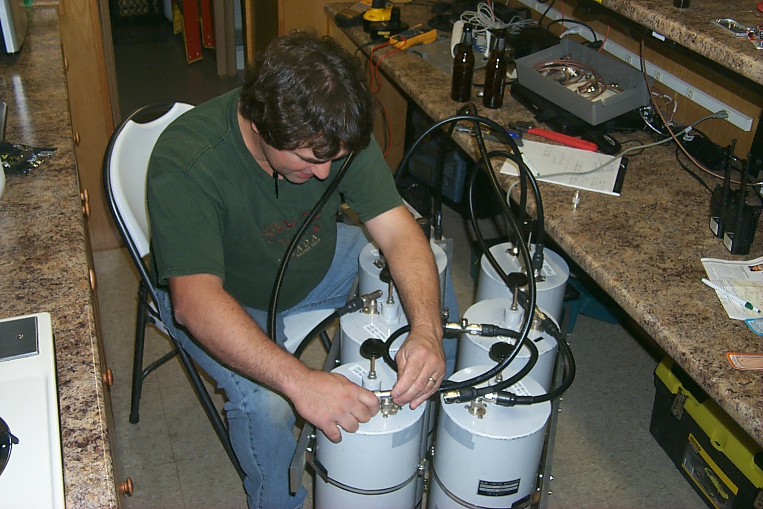
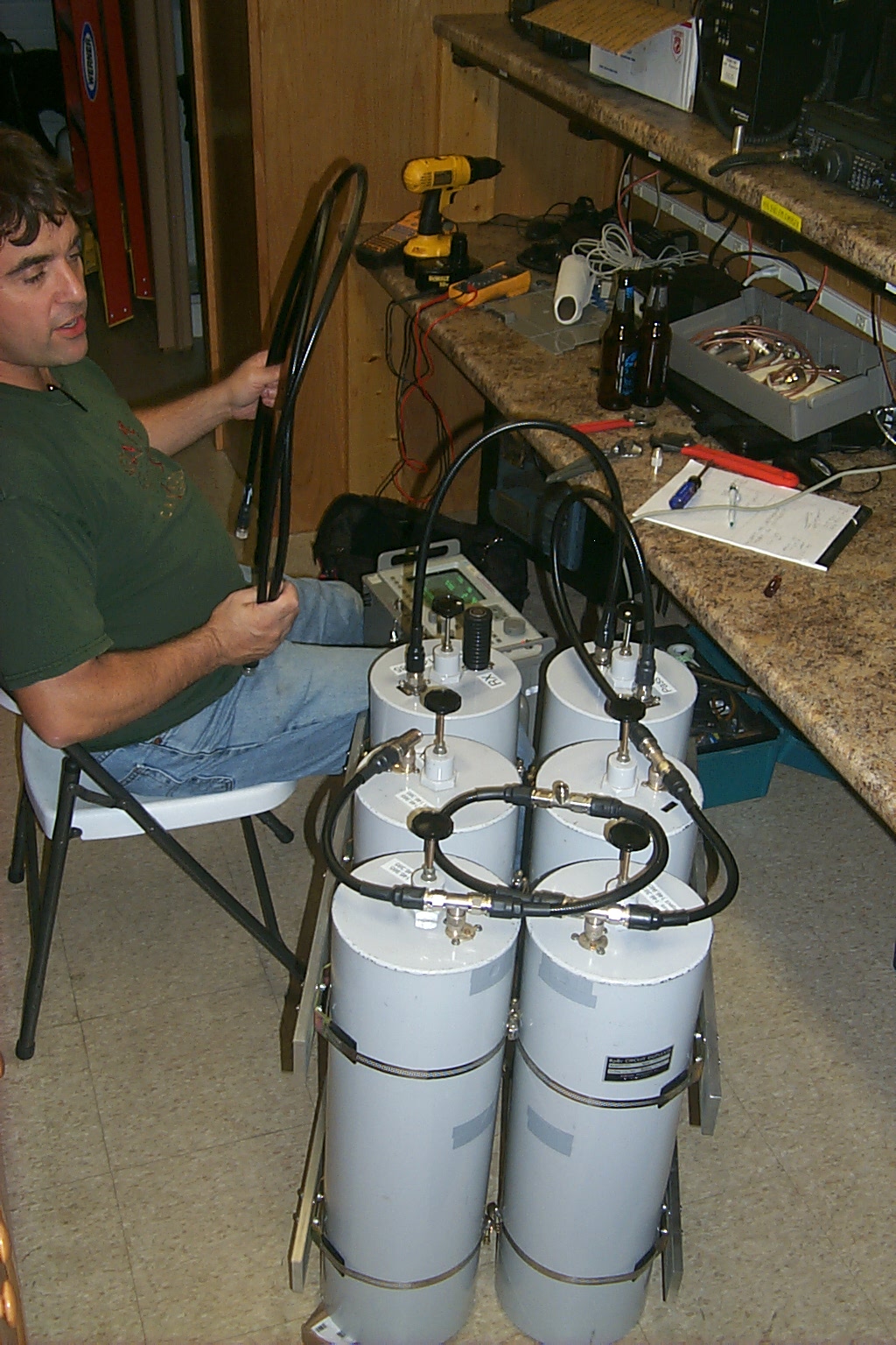
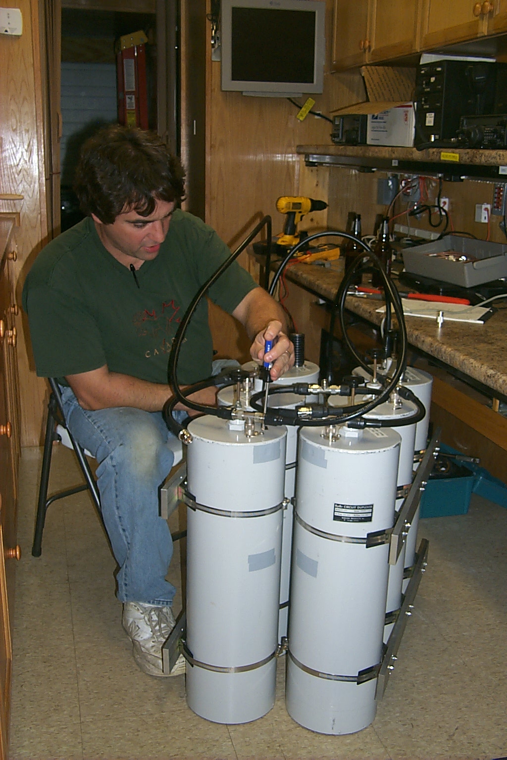
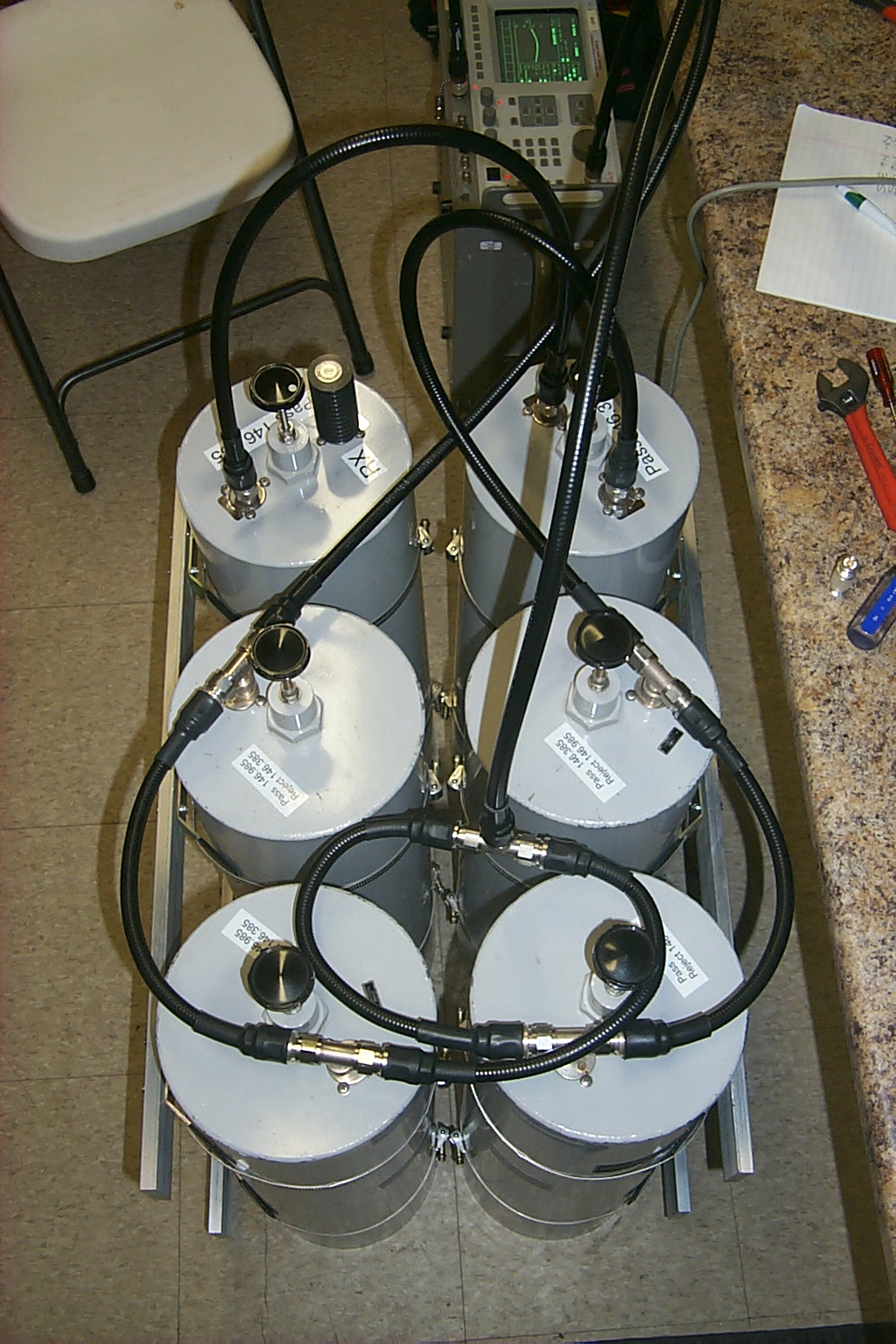
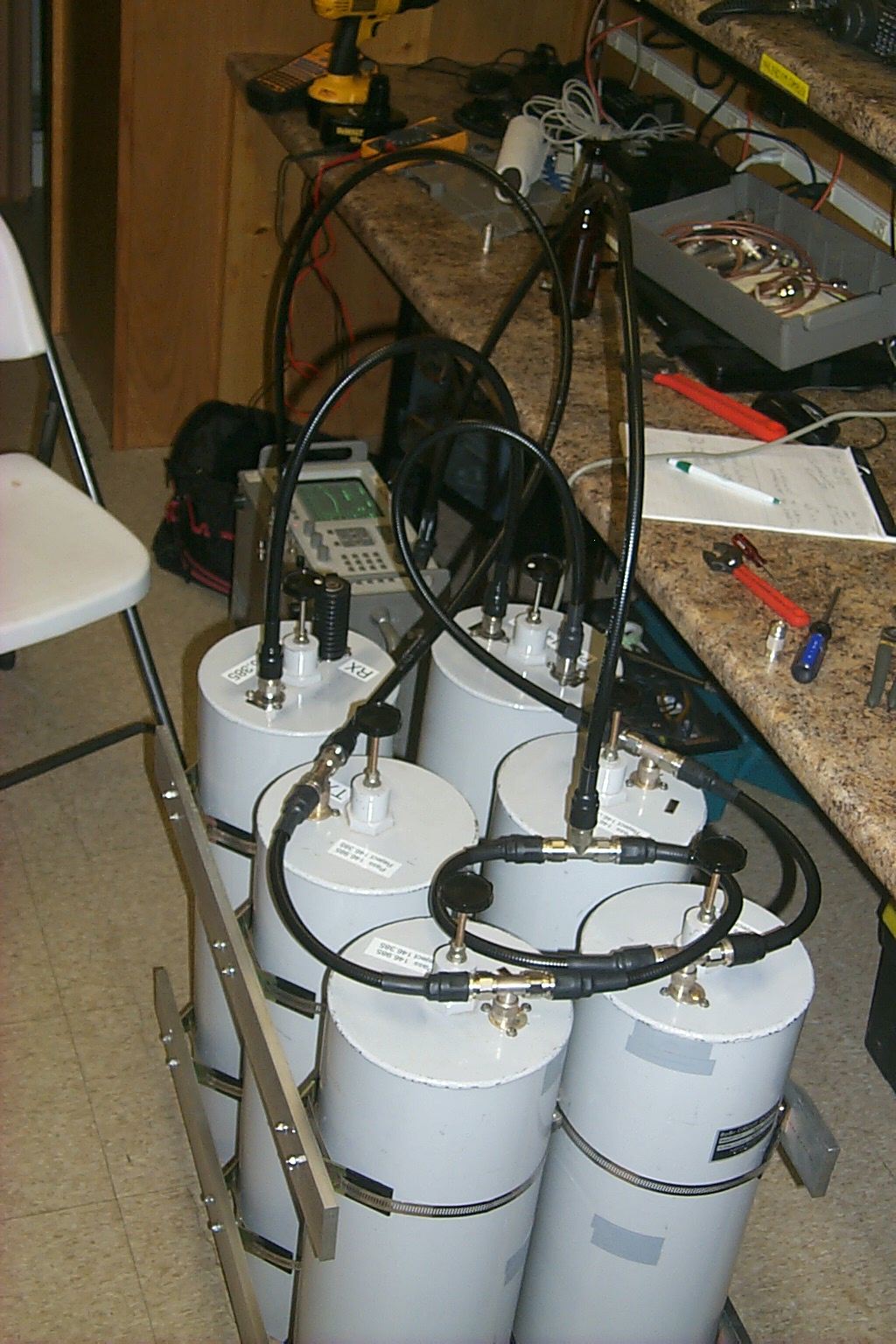
I did some testing with my new RC-210 controller with this hardware, the RC-210 would eventually be deployed at the Johnston site running the 145.190 / 223.960 / 449.325 repeaters. In the photos below you can see a set of Sinclair VHF duplexers that I purchased for this project; I bolted the repeater cabinet to the top of the duplexer cabinet making one stable unit that can be easily deployed and moved around.
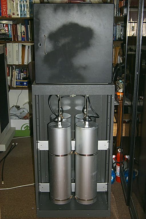
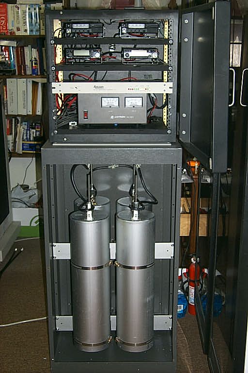
(click on images to enlarge)
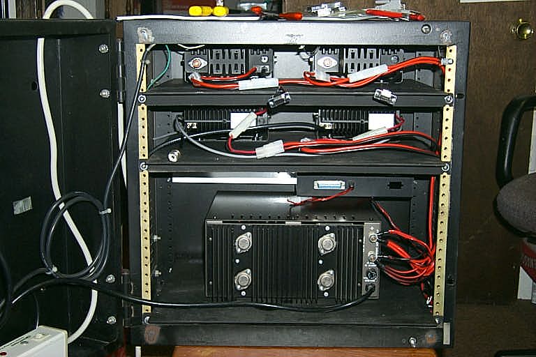
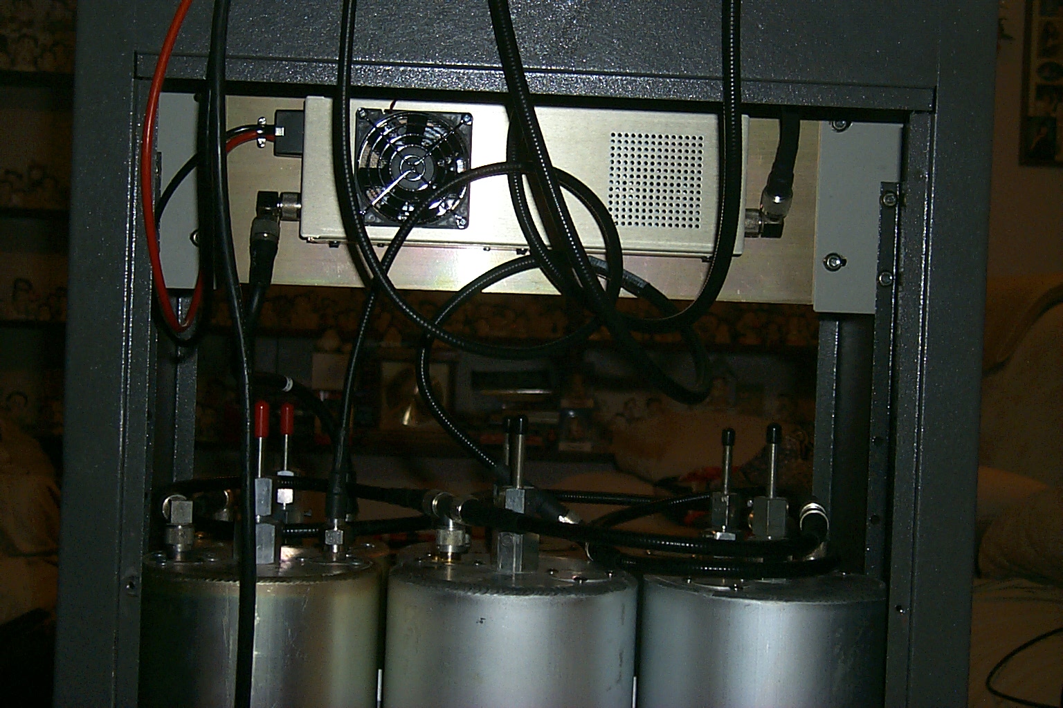
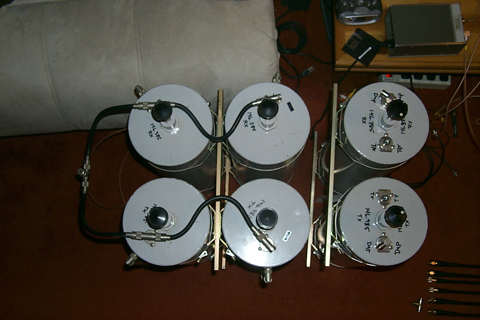
I was able to route the RF cables out the back of the repeater cabinet and make the connections to the duplexer.
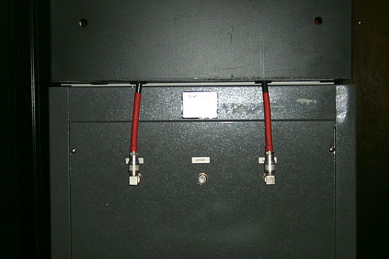
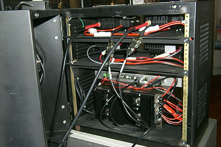
(click on images to enlarge)
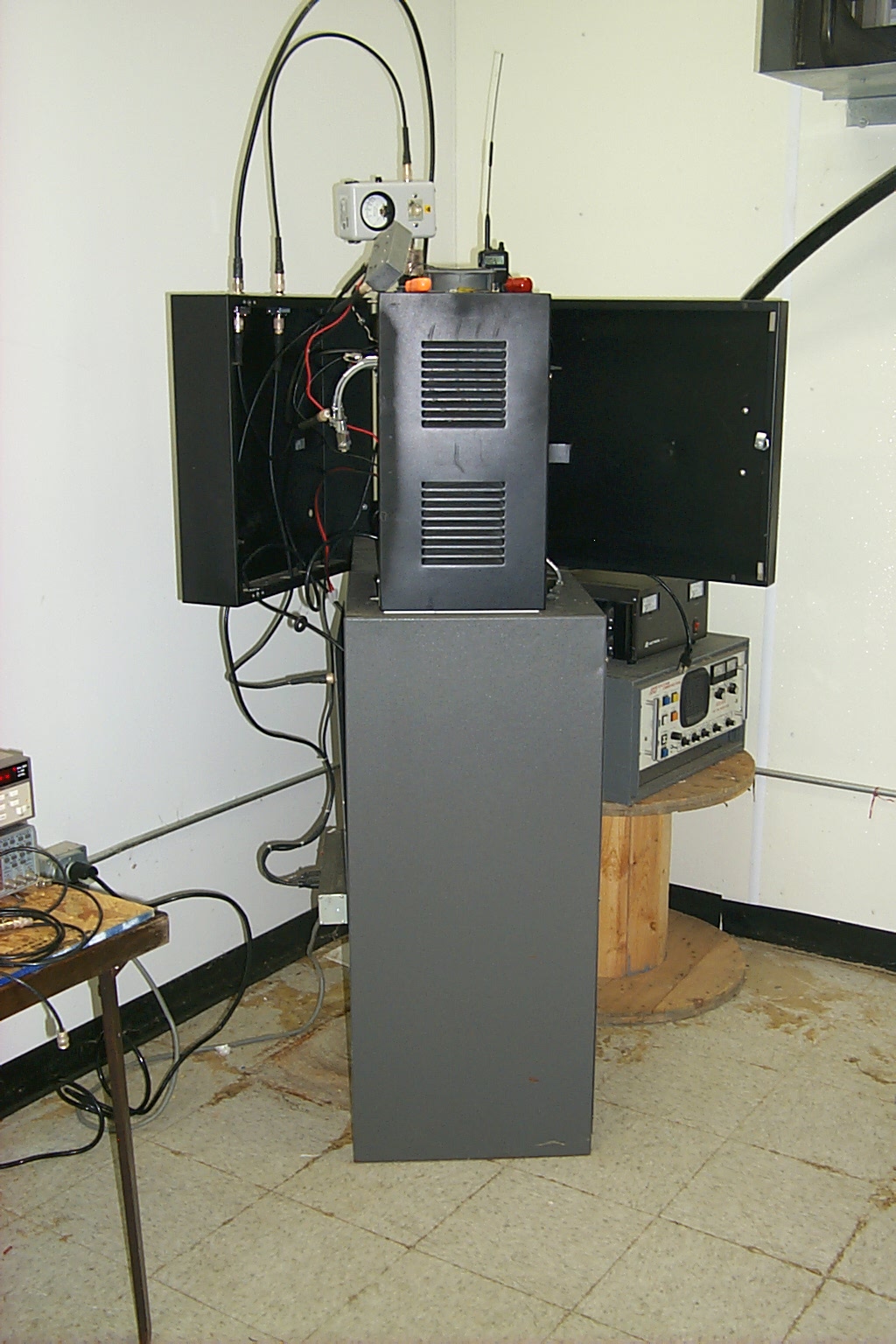
Once Joe completes the work building the new .985 repeater I can re-deploy this hardware to another site and frequency pair. I have access to a great site in Portsmouth RI where this repeater will eventually be move to and linked into the KA1RCI network.
On the air at the Exeter site...
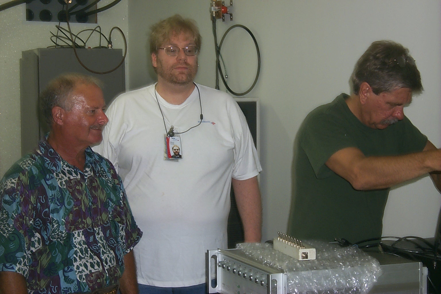
(click on images to enlarge)
Update December 2007 - Repairs / Upgrade
In the fall of 2007, after three years of service, the 146.985 repeater started developing some odd behaviors, the transmitters finals blew and the power supply was acting up. I have been so impressed with the old Kenwood TK-30 Series hardware that I used on the 147.075 and 147.390 repeaters that I decided to upgrade the 146.985 repeater with a new larger power supply and Kenwood TK-30 radios.
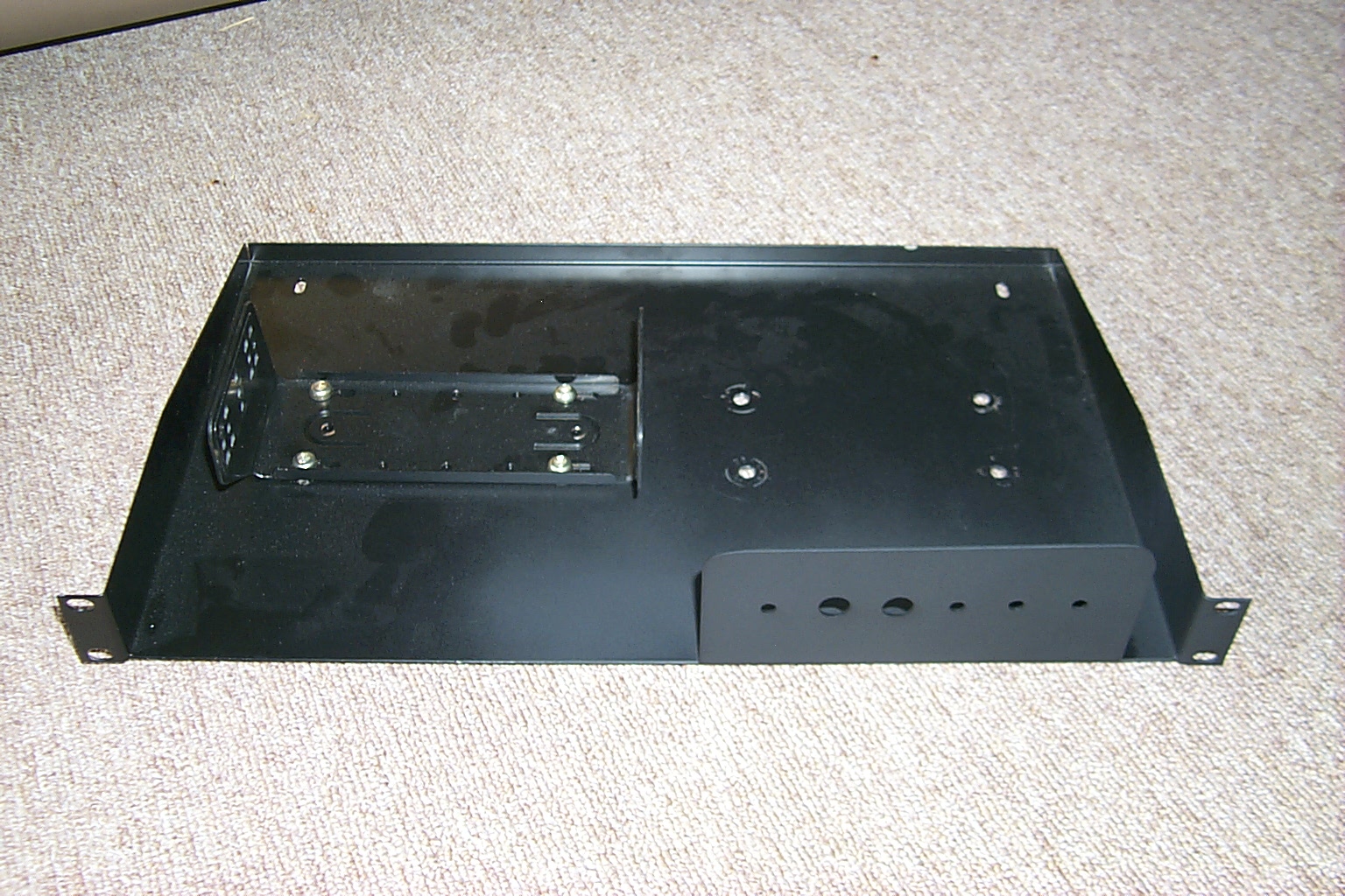
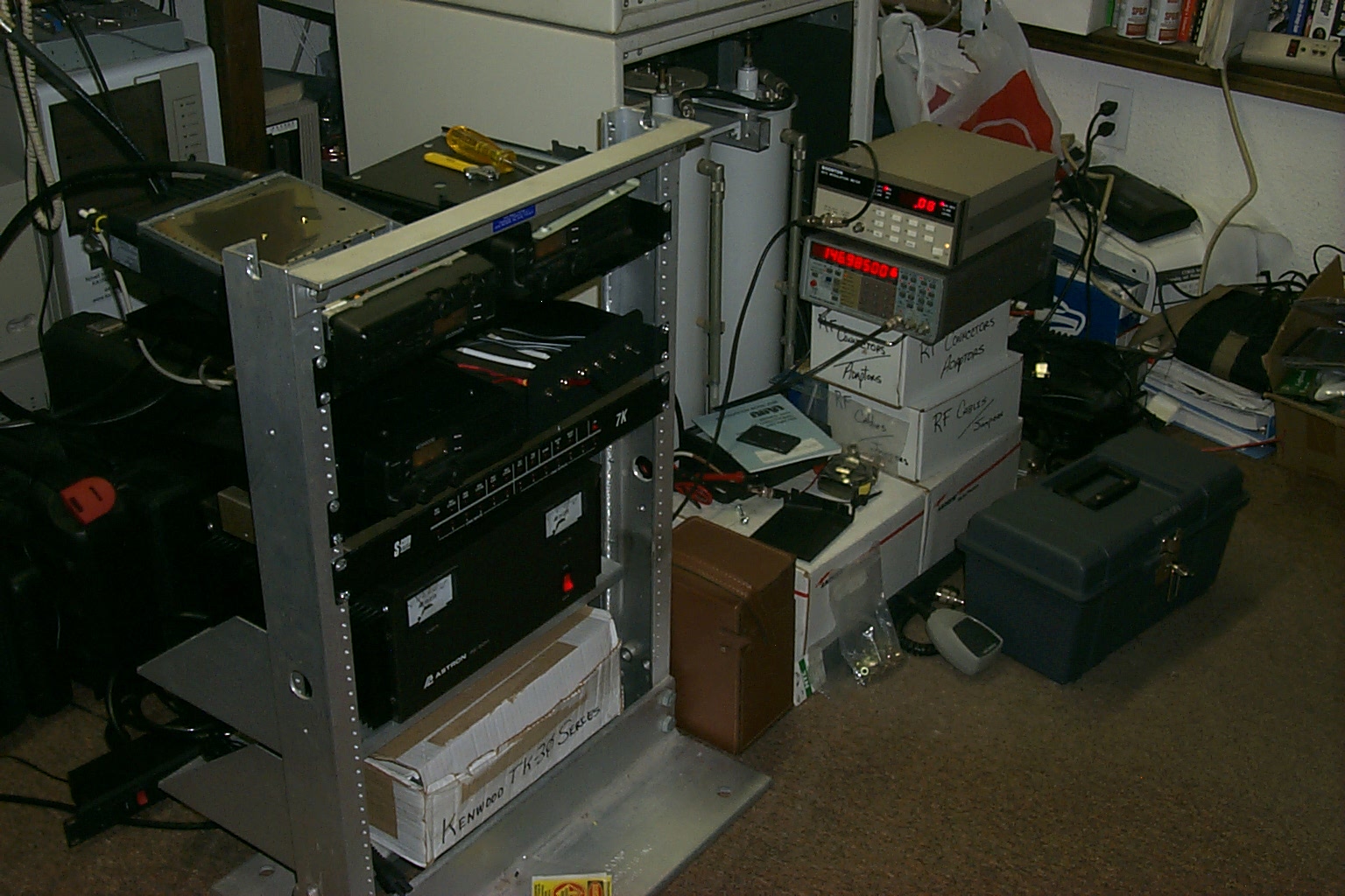
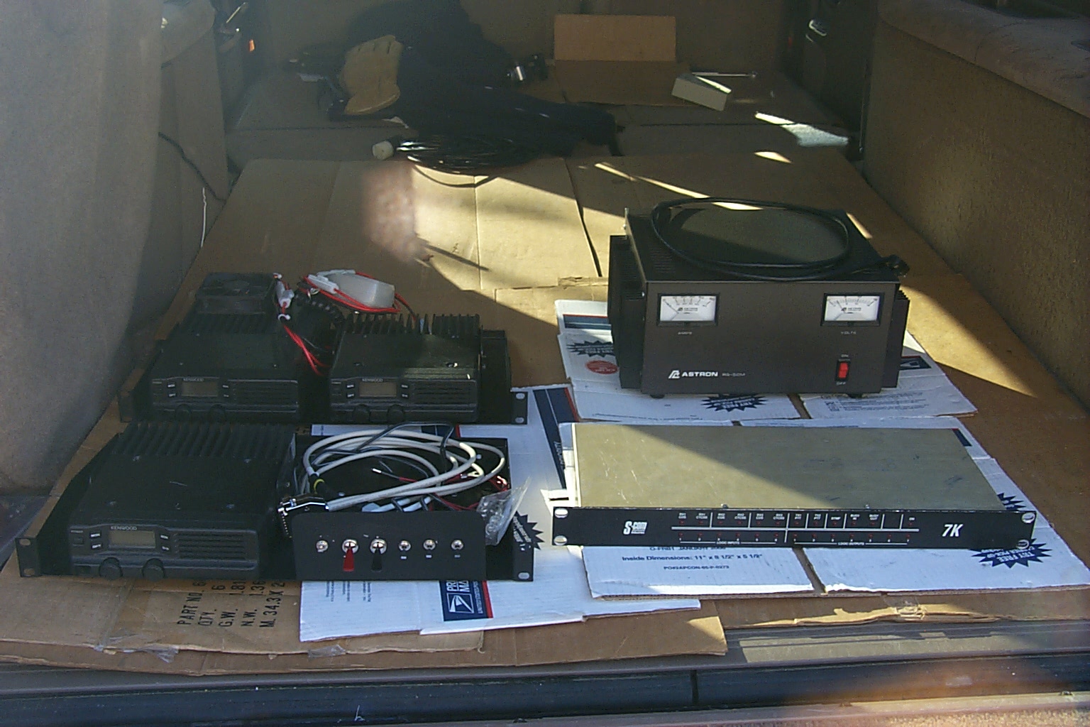
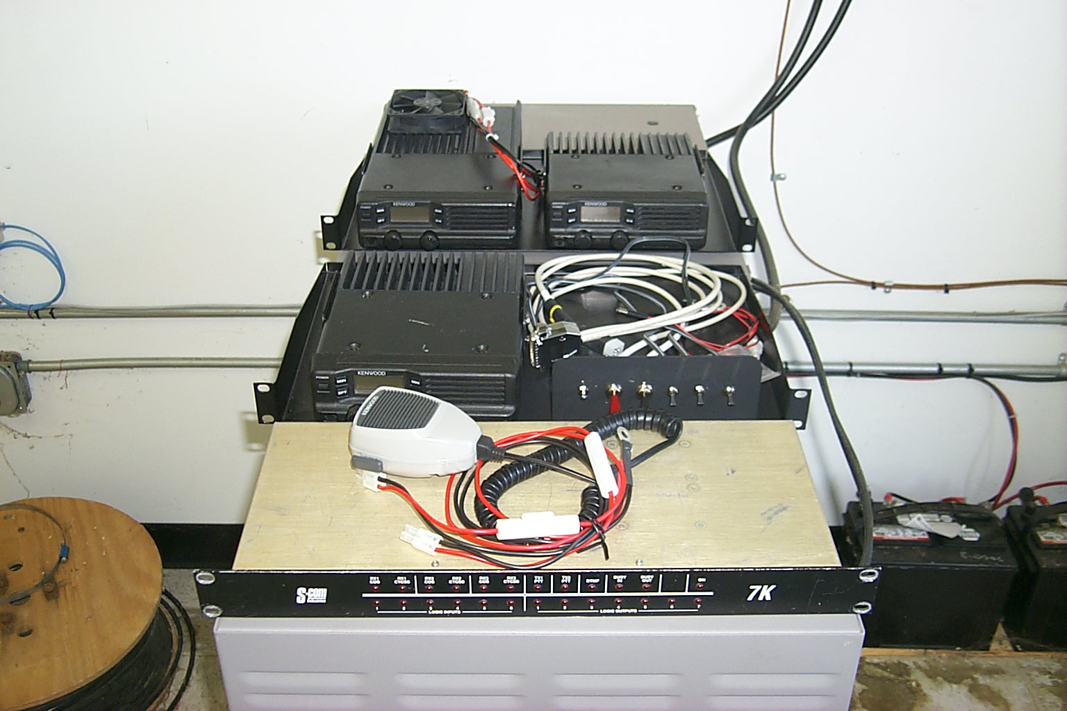
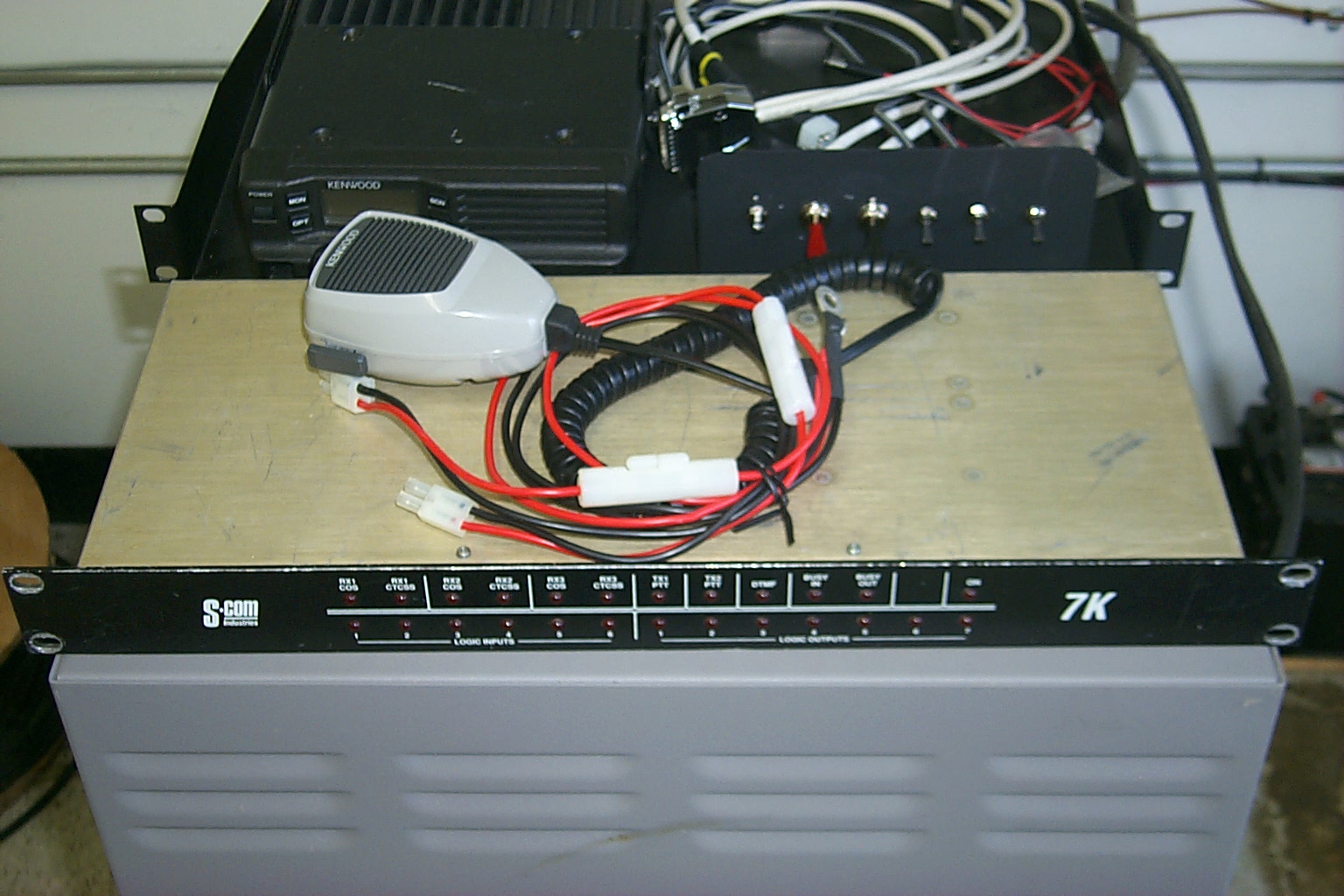
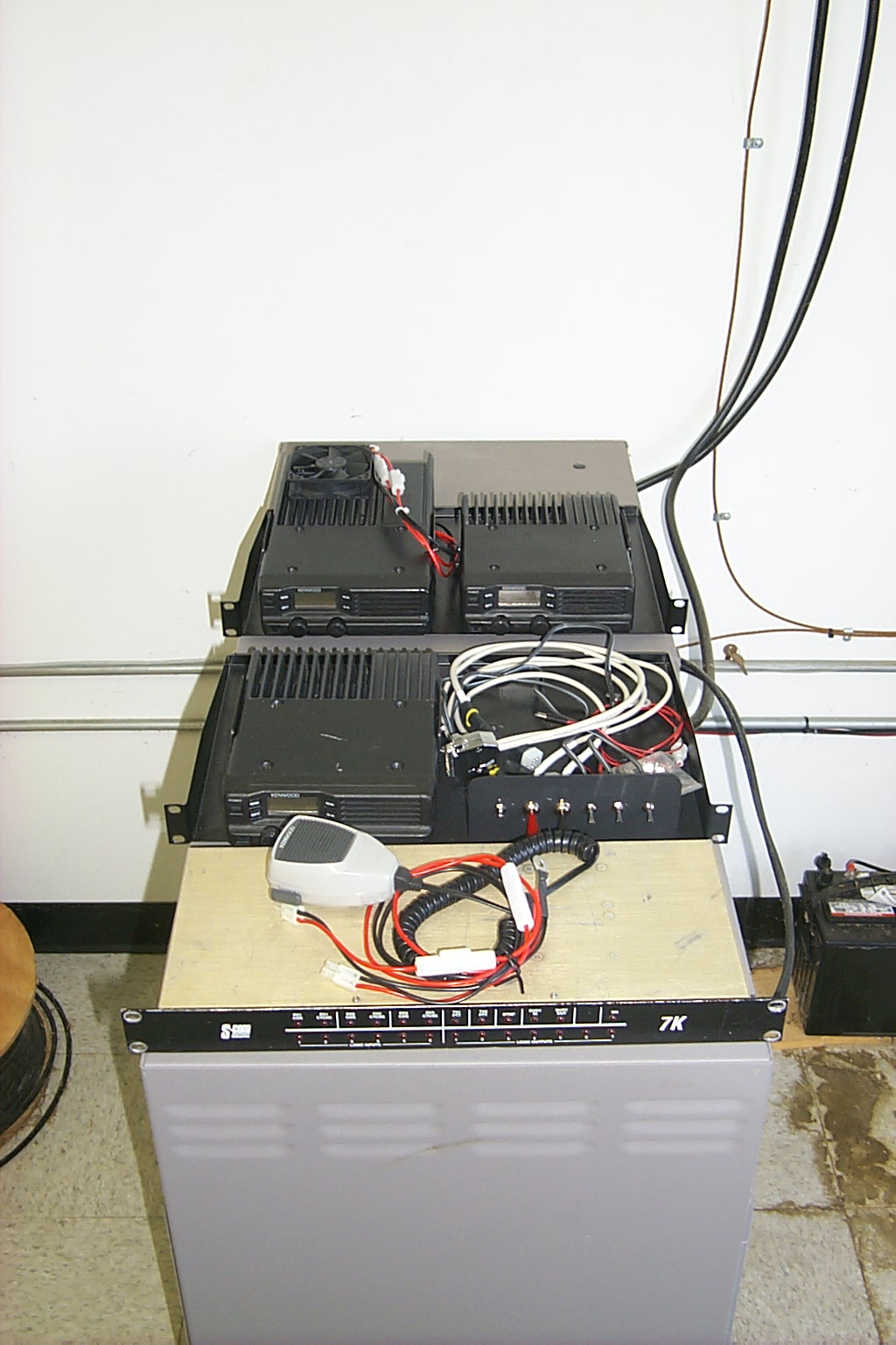
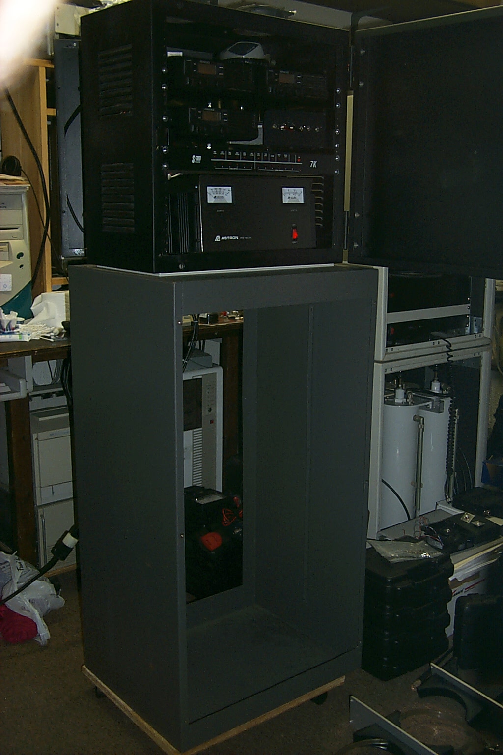
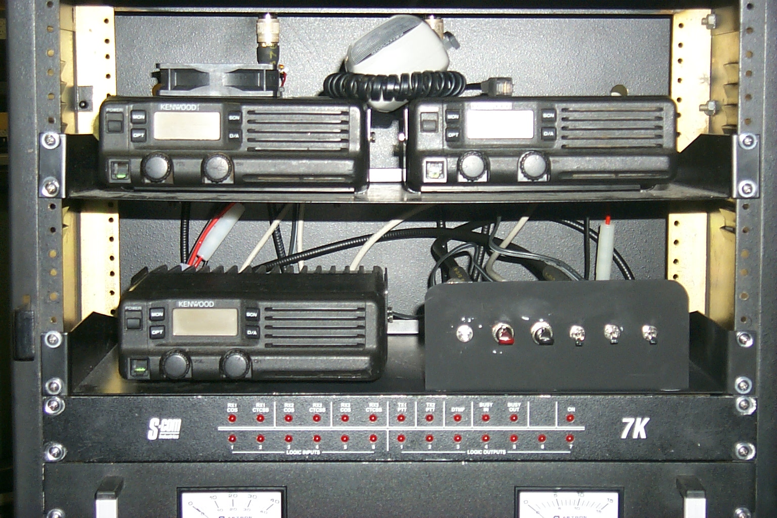
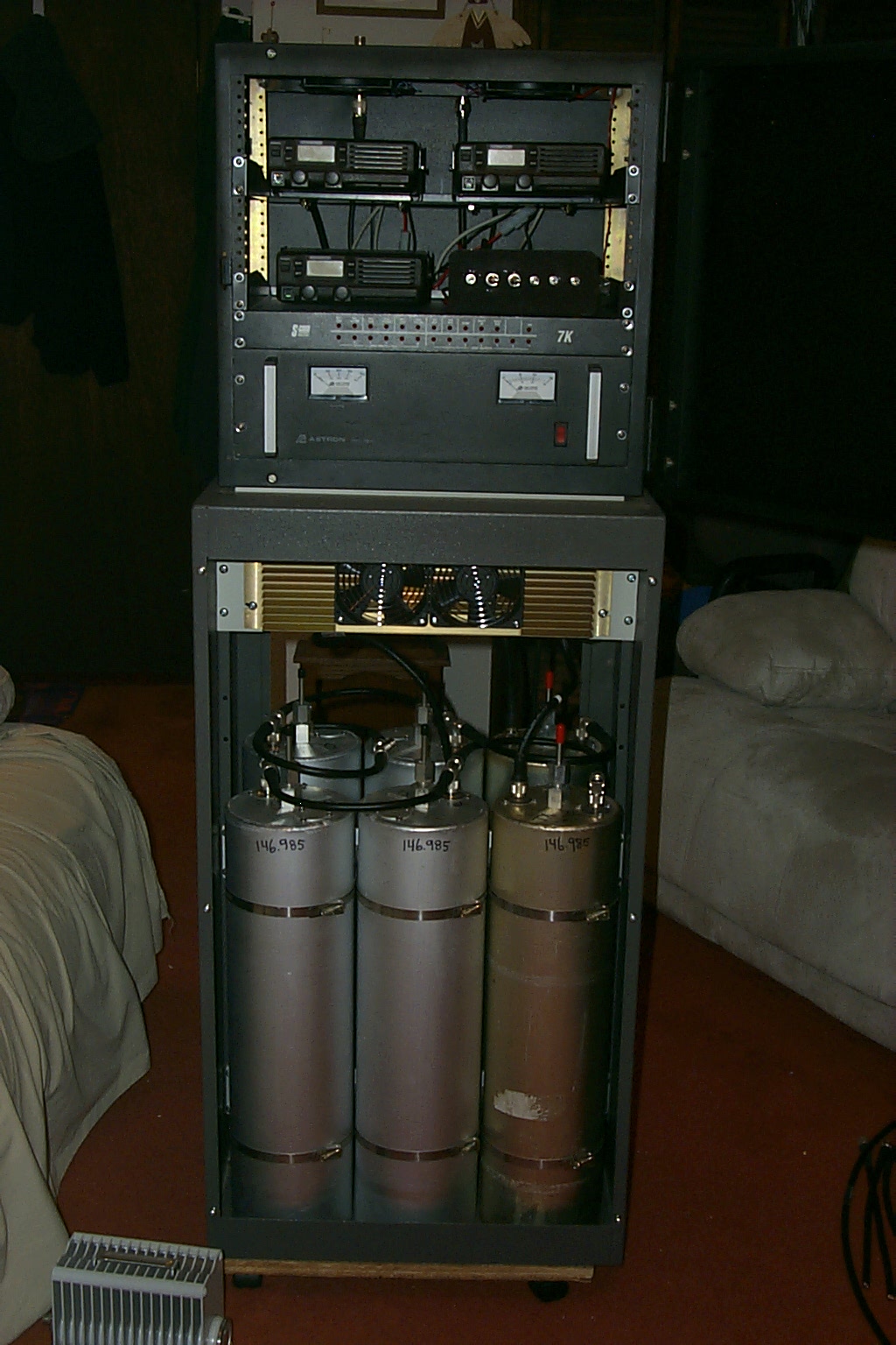
Starting with a small free standing rack mount I gathered all the components that I would need to build out the new S-Com 7K / TK-30 Series repeater that could be build into the existing 146.985 rack cabinet.
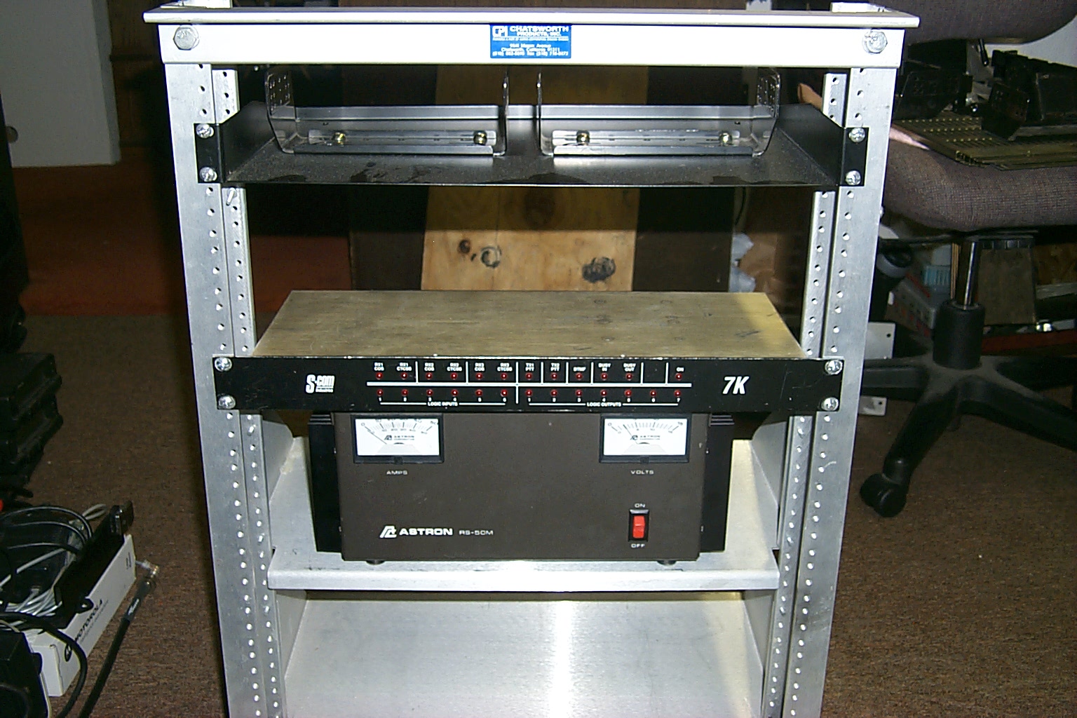
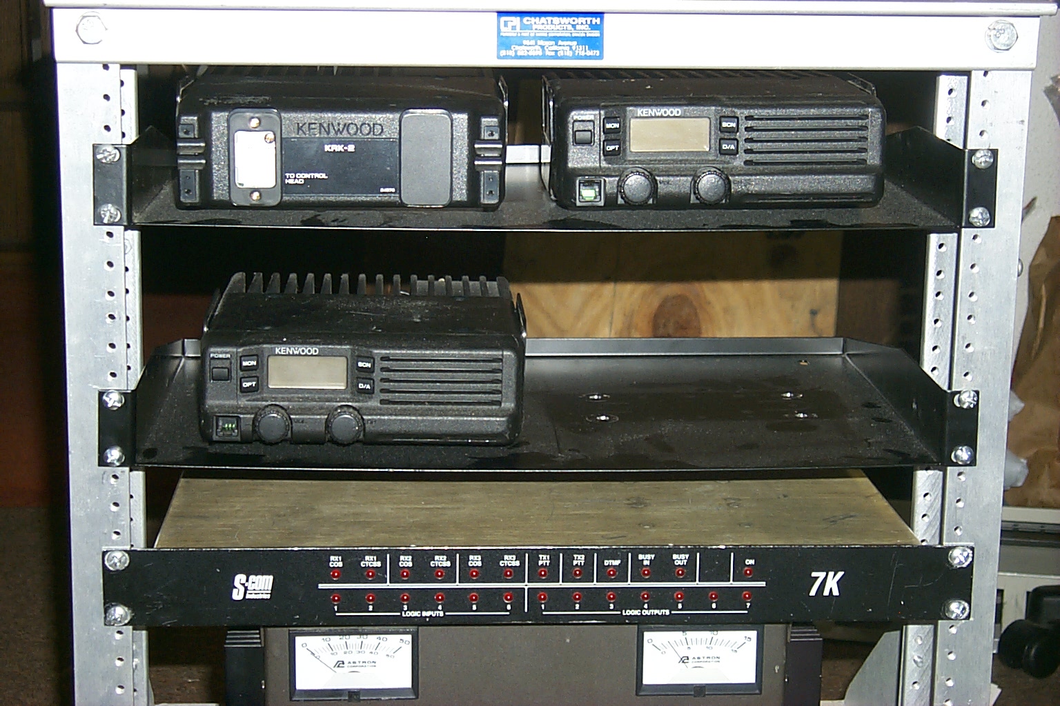
(click on images to enlarge)
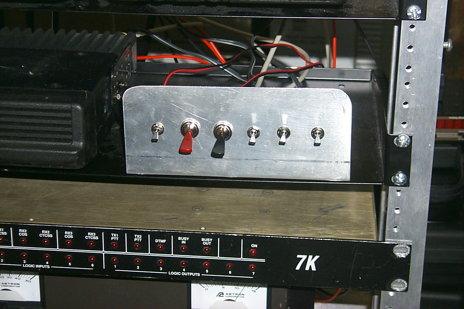
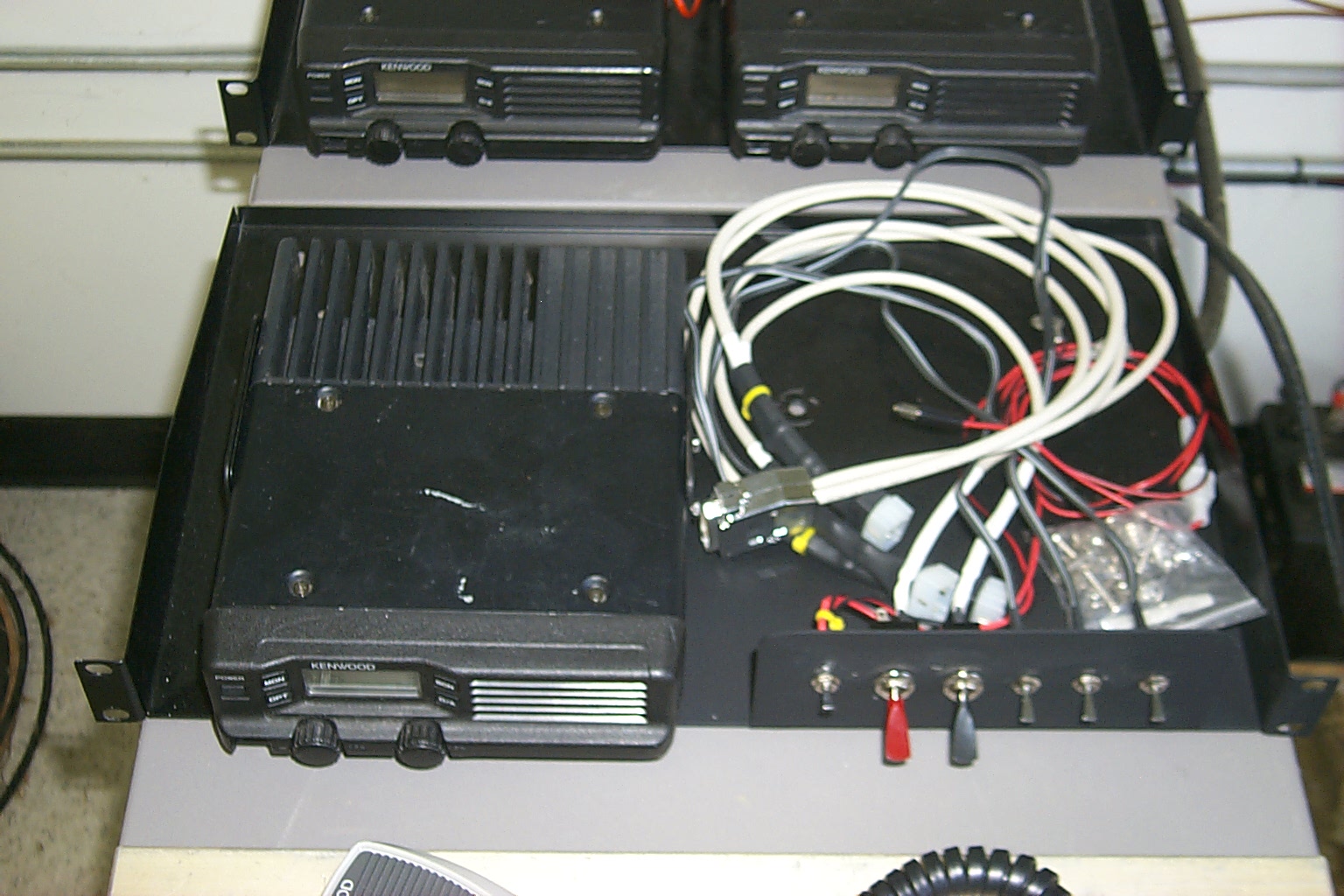
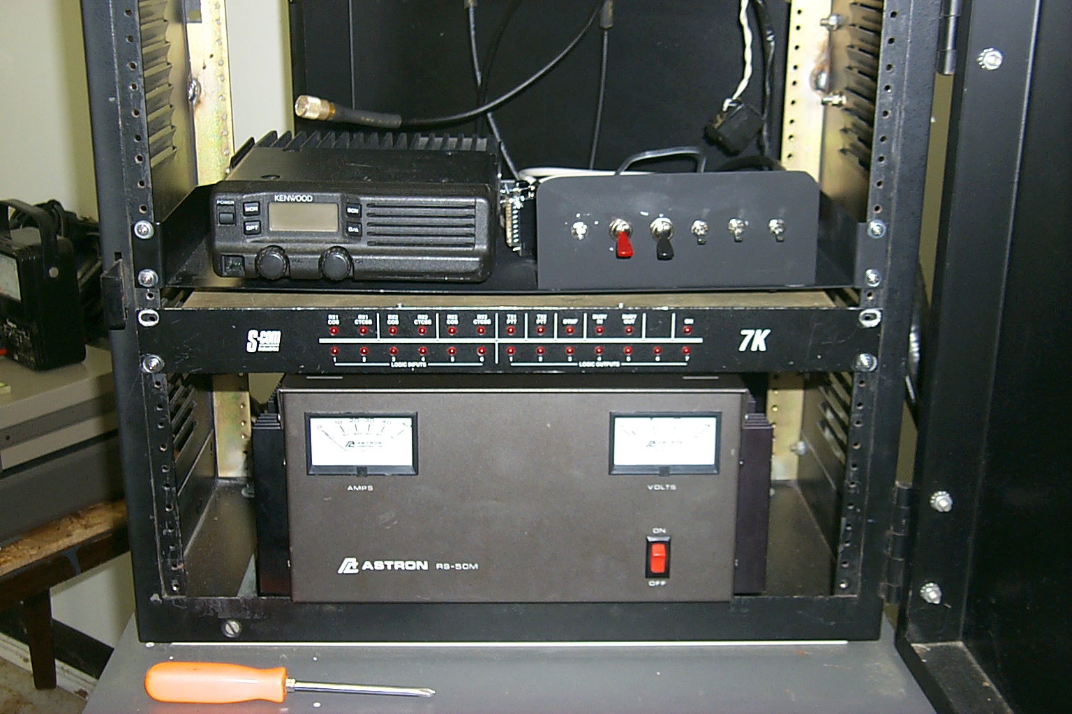
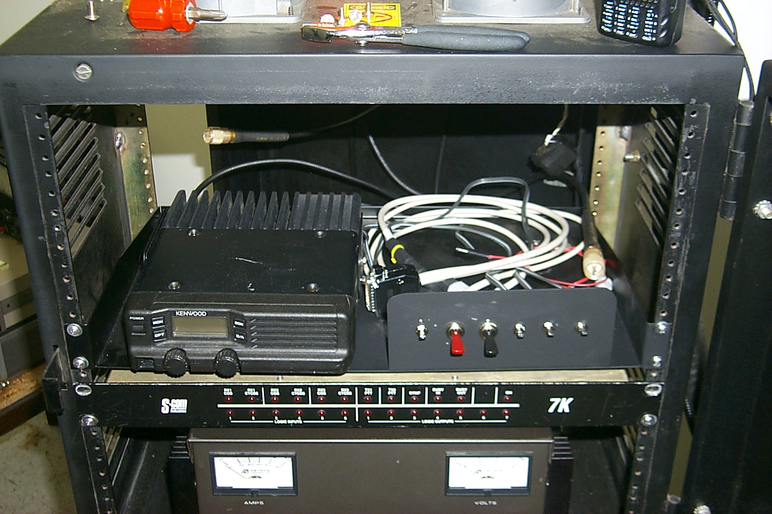
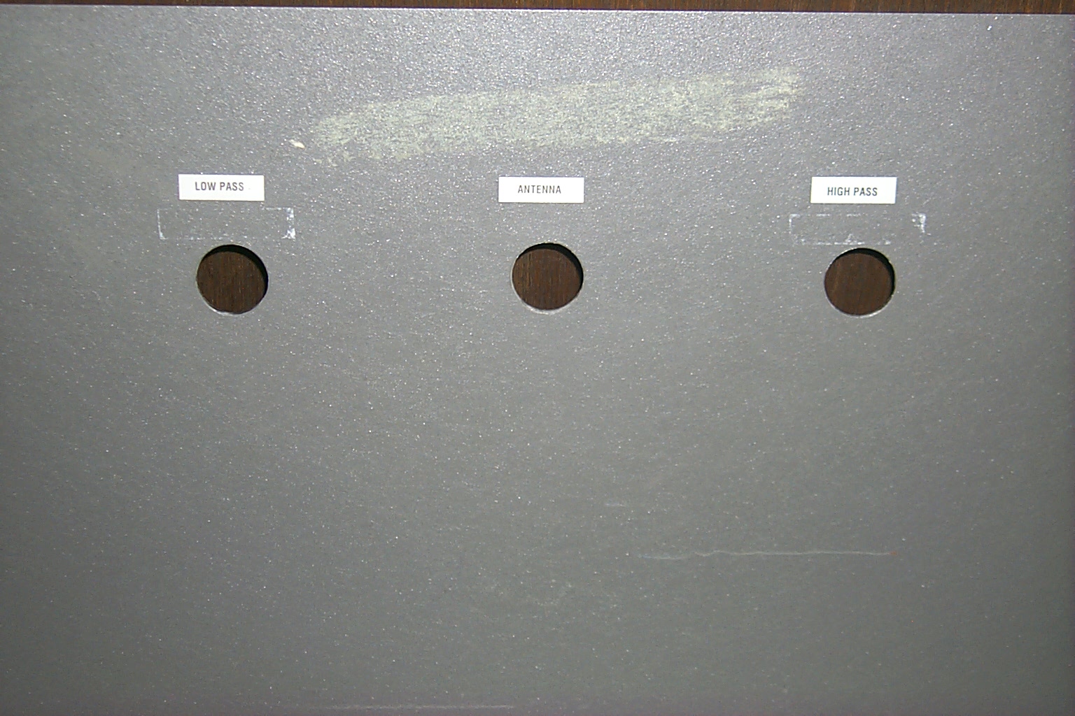
I built a custom control cable to connect the TK-30 series radios to the S-Com 7K controller just like the one I developed for the 147.390 project with mini toggles to turn the local speakers on and off, turn the controller on and off, and select the two transmitters TX mode between ON/CTRL/OFF making it easy to work on and reset the repeater.
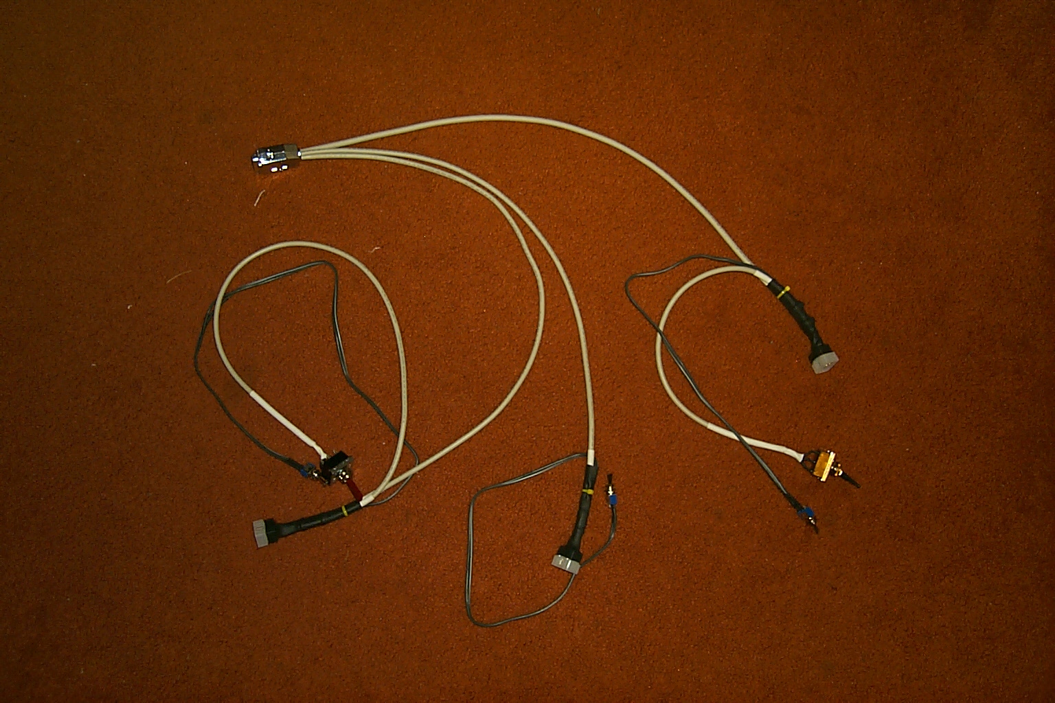
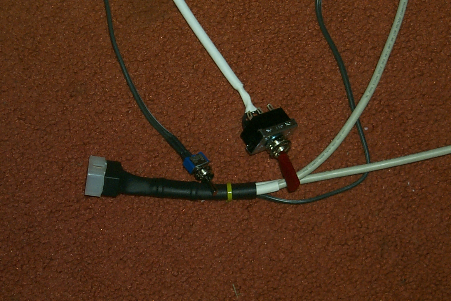
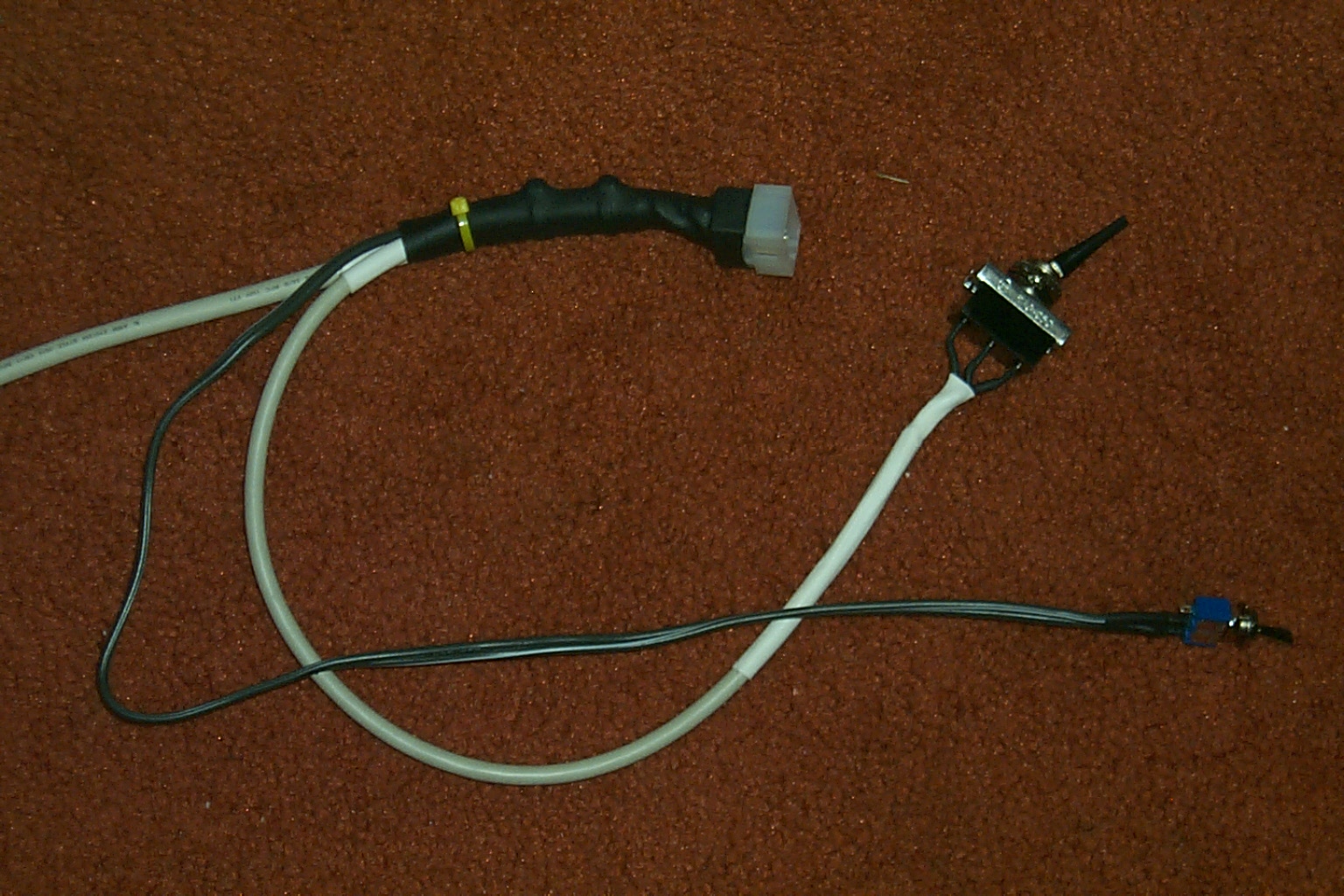

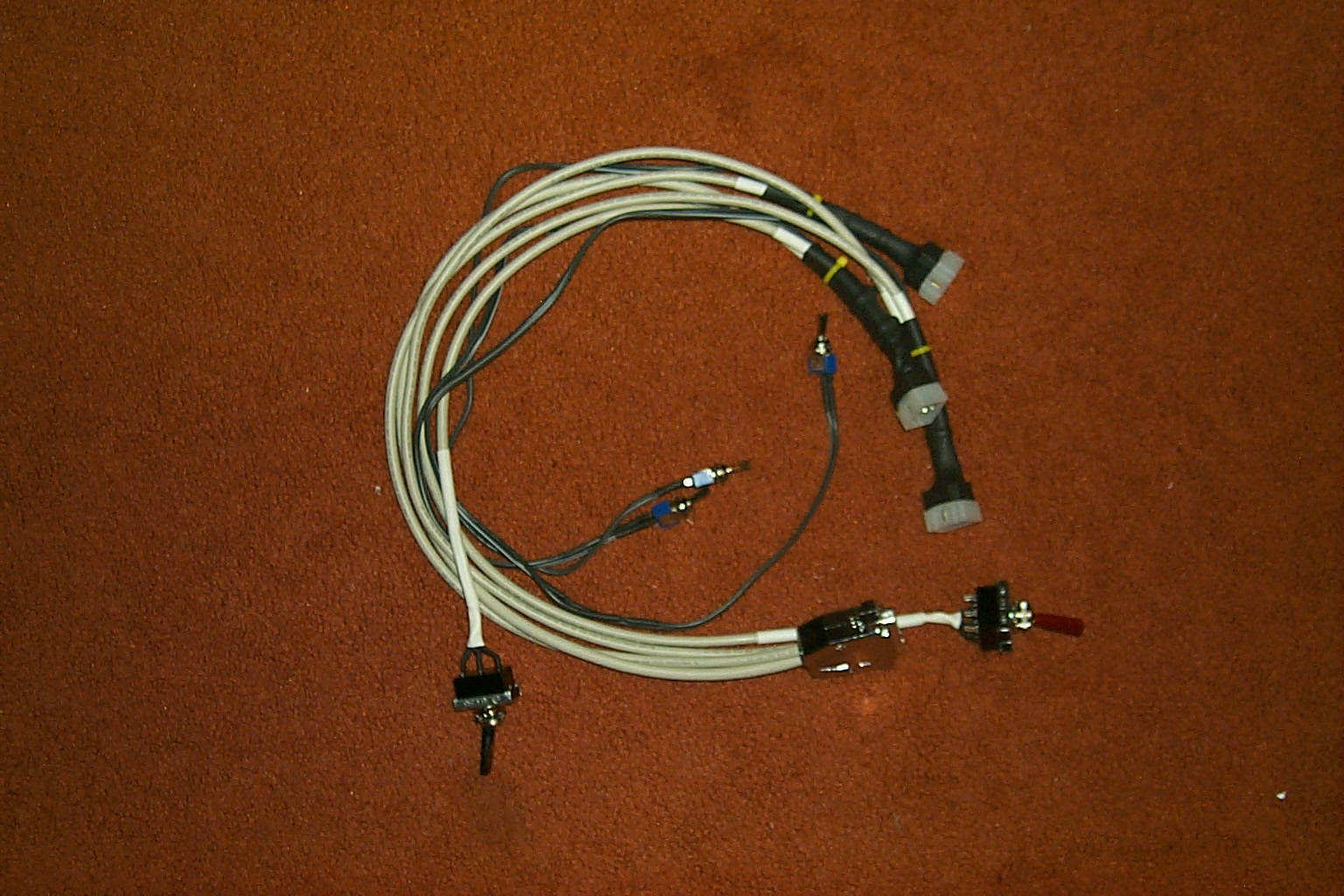
(click on images to enlarge)
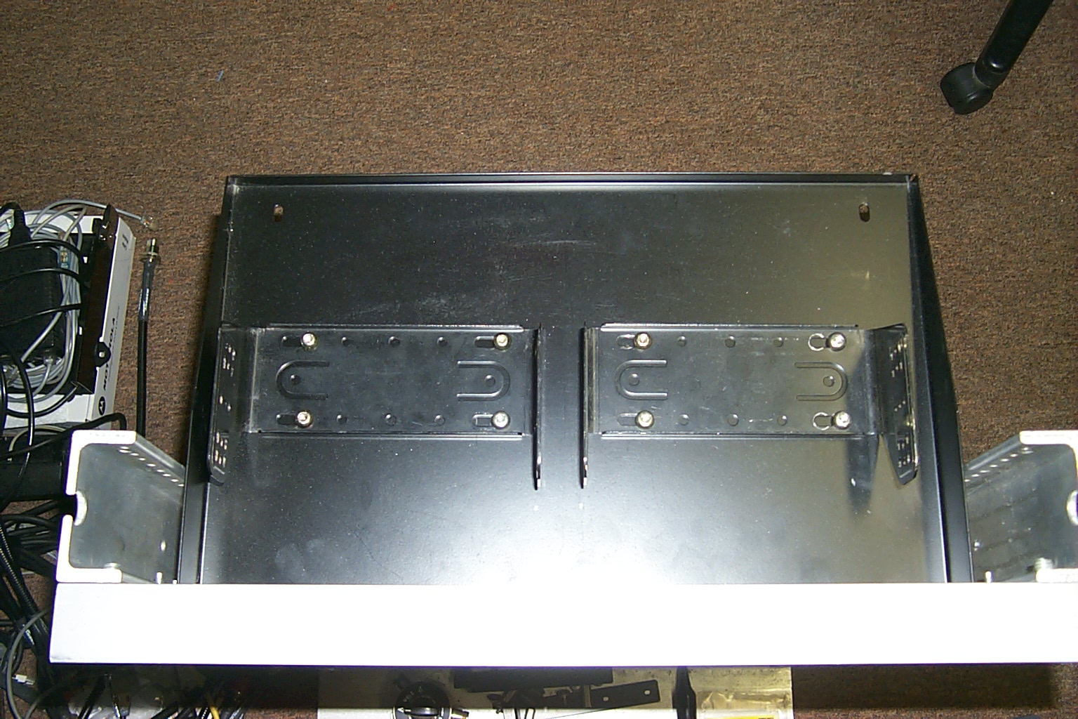
Once I had the control cable assembled I needed someplace to mount all those toggle switches, Bruce KD1BE and Jon N1WEM fabricated a custom bracket that I could bolt to the rack shelf that all the toggle switches would mount in.
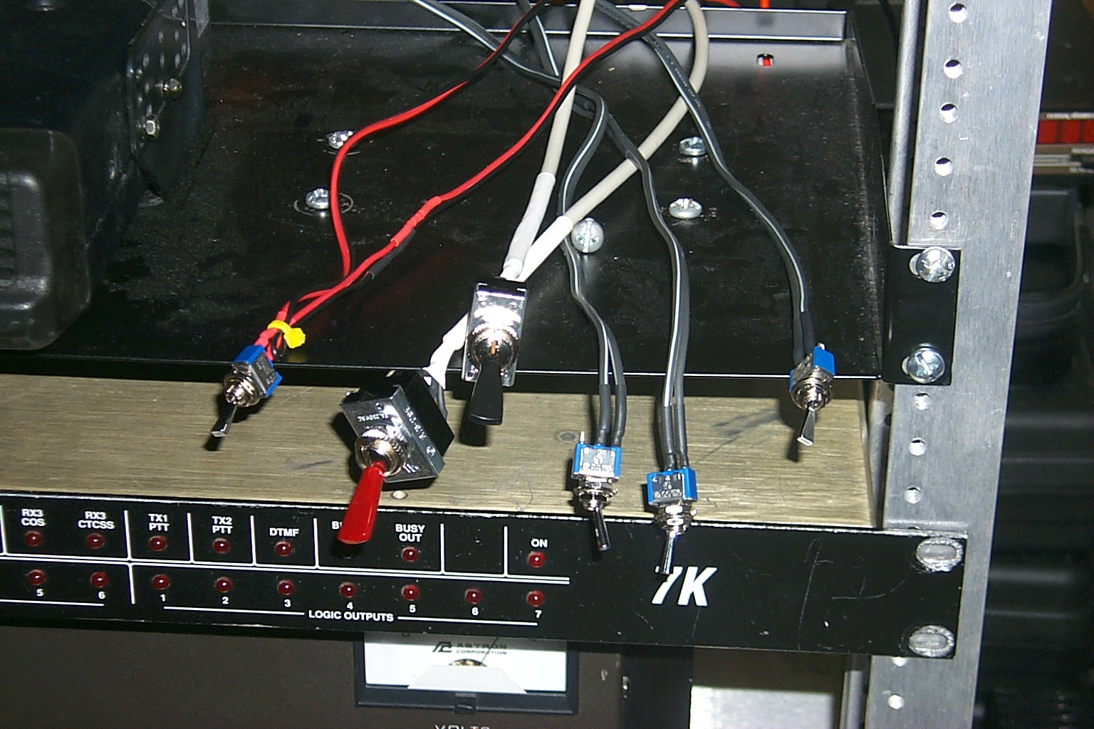
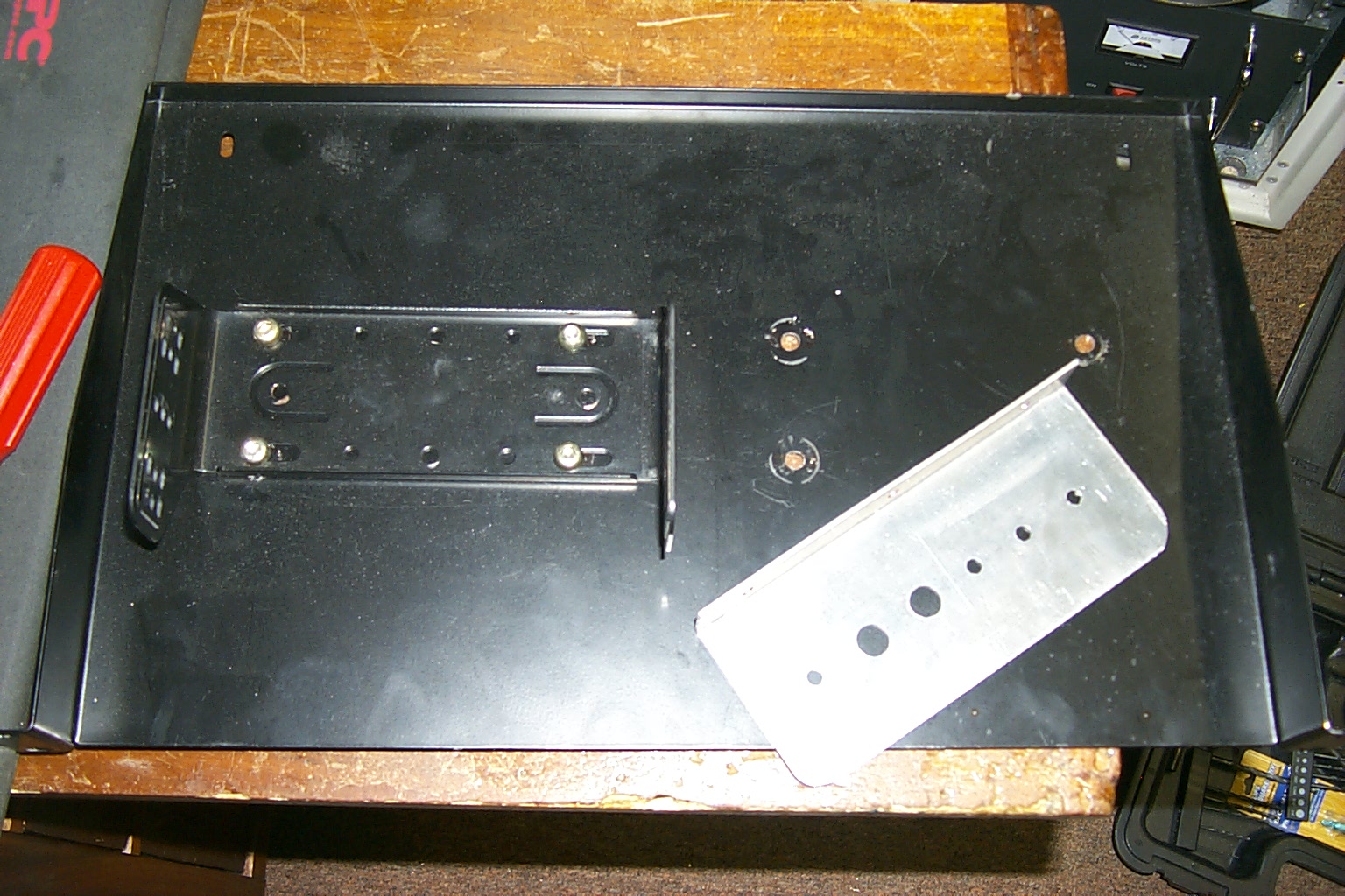
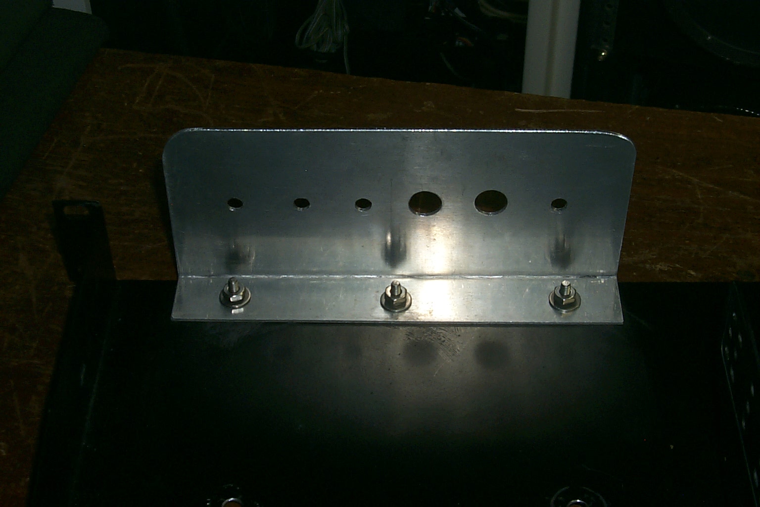
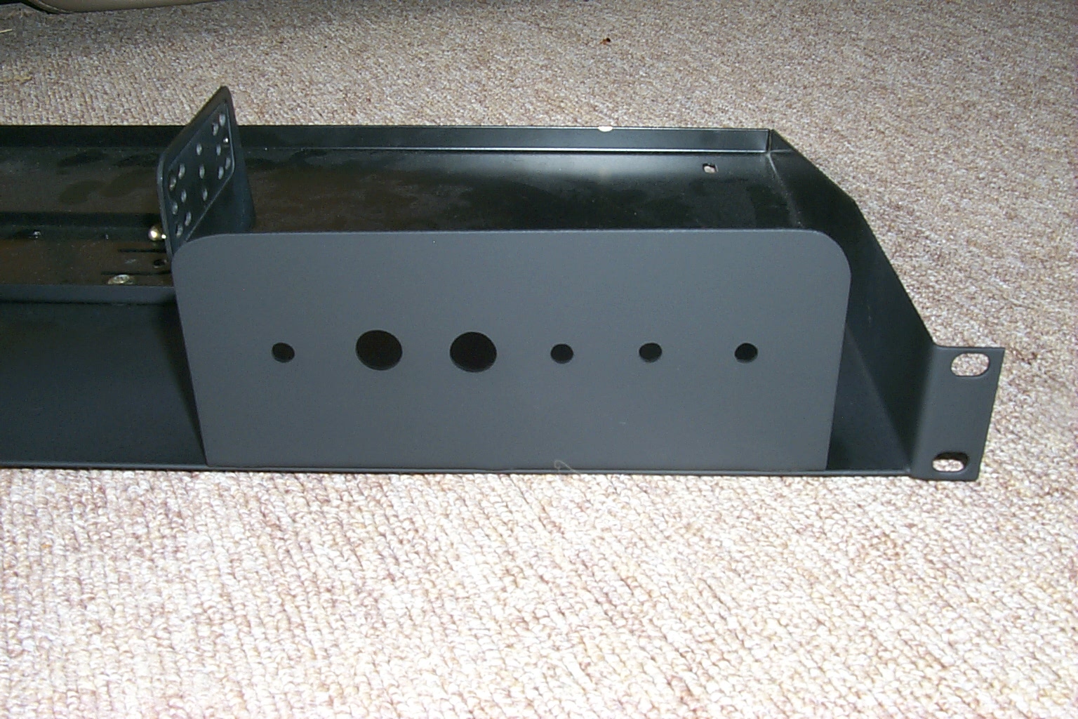
(click on images to enlarge)
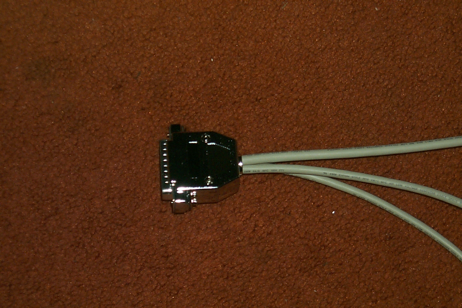
After running the repeater at my QTH in Lincoln a few days to get the controller programmed and adjust the audio levels I noticed that the six pin Molex connector on the TK-730H that was the primary repeater transmitter was not making a very good connection and that the radio would turn on and off if you bumped the rack or jiggled the power cable. I decided to remove the Molex connector and hardwire the DC power cable directly to the radio.
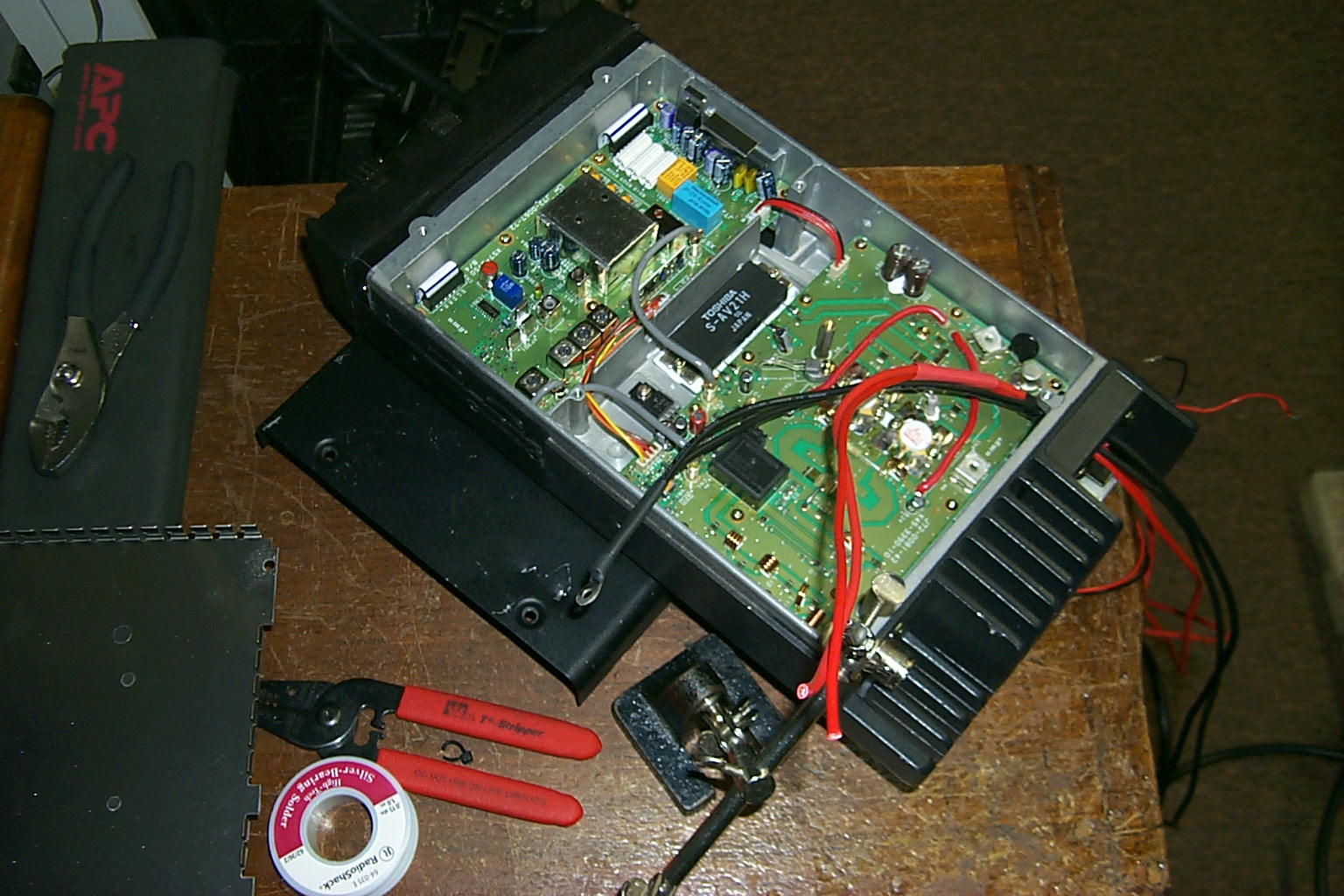
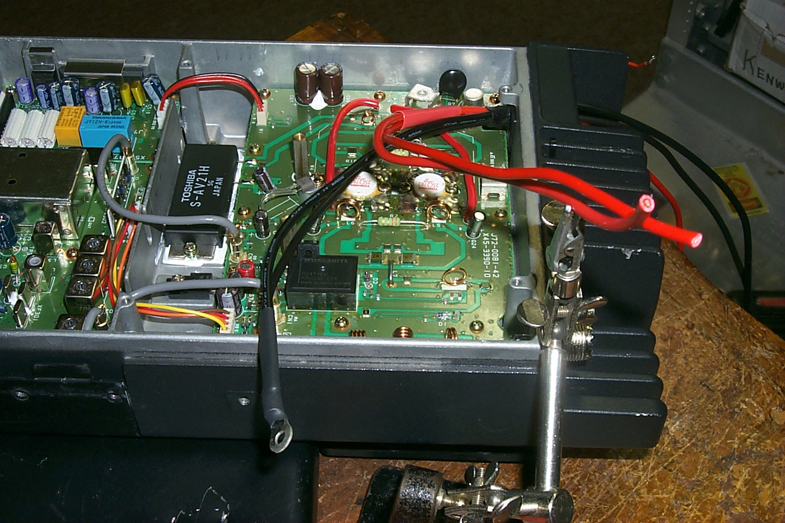
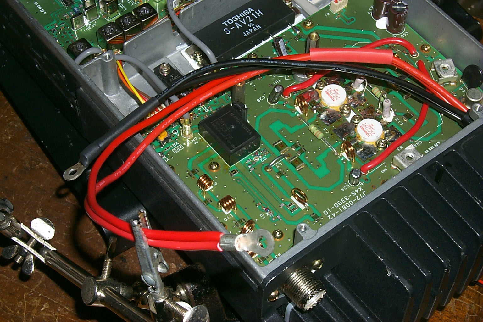
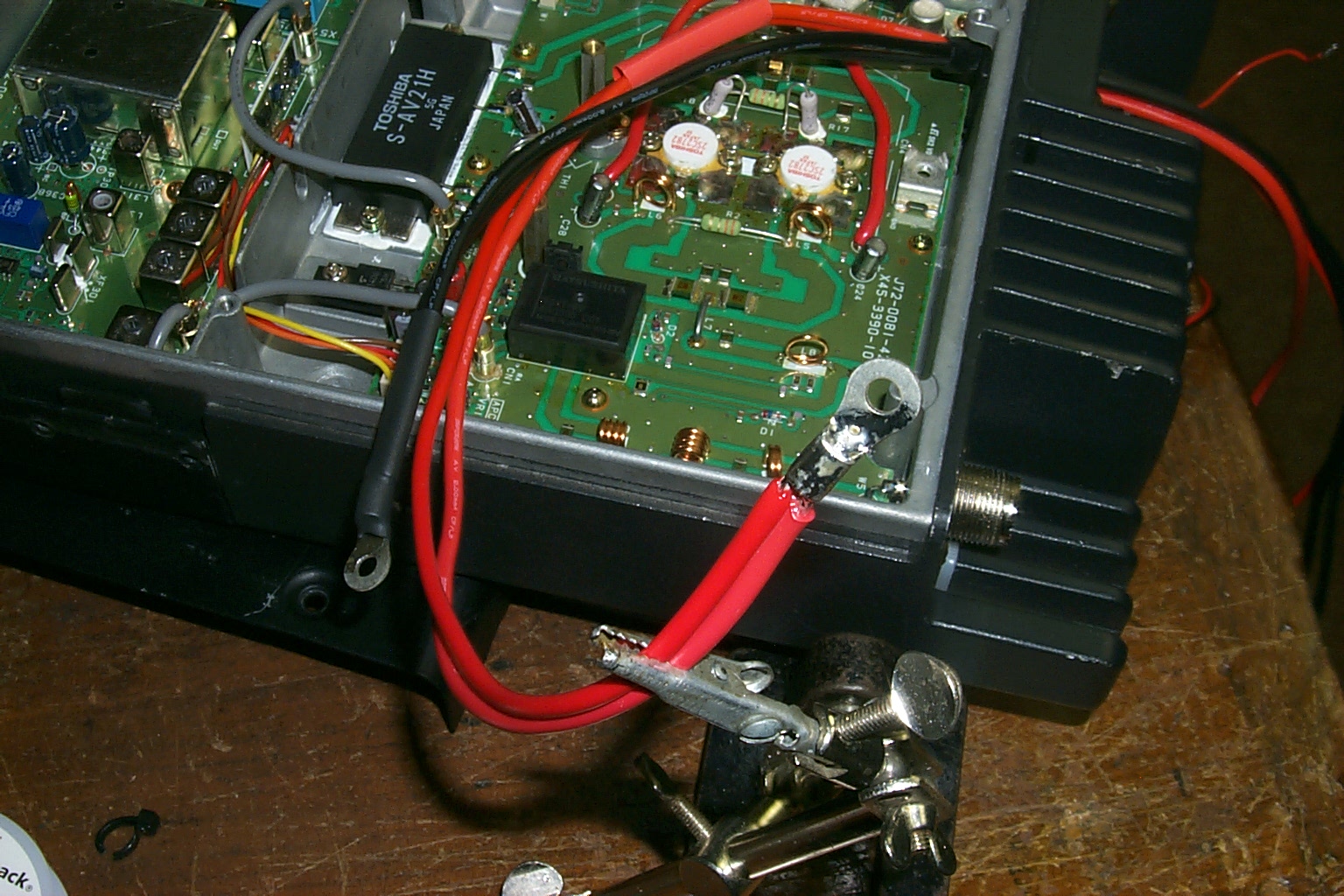
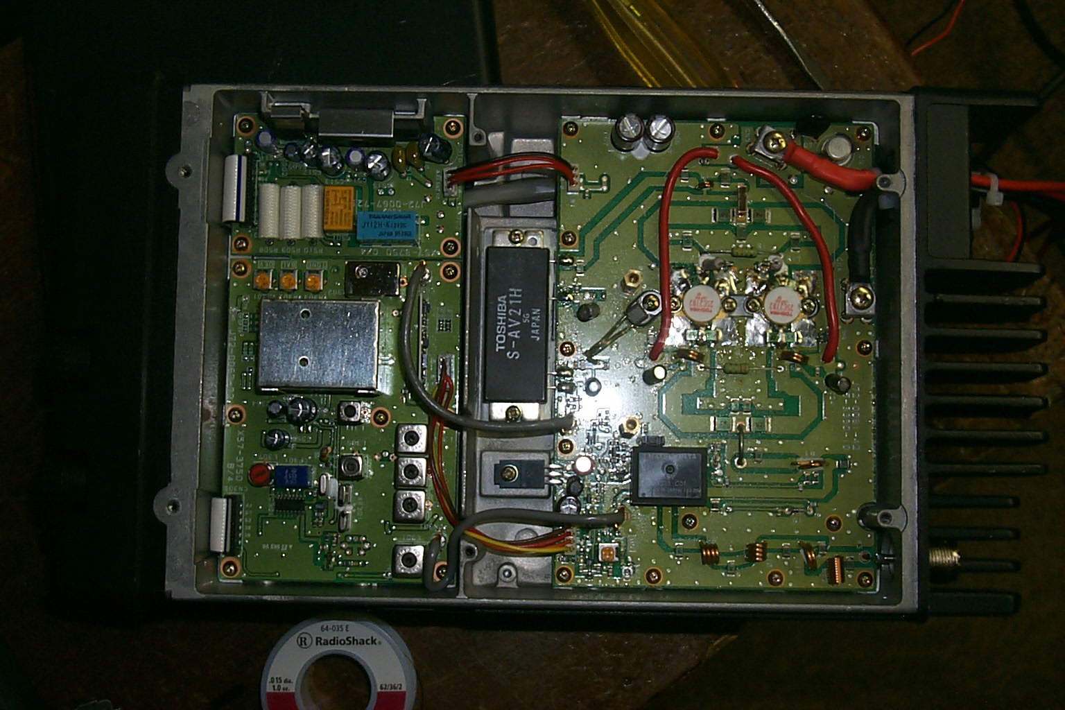
(click on images to enlarge)
Another day of testing on the air at my QTH in Lincoln , some fine tuning making sure the repeater was on frequency and that the CTCSS encode levels were set correctly before deploying the new hardware to the site.
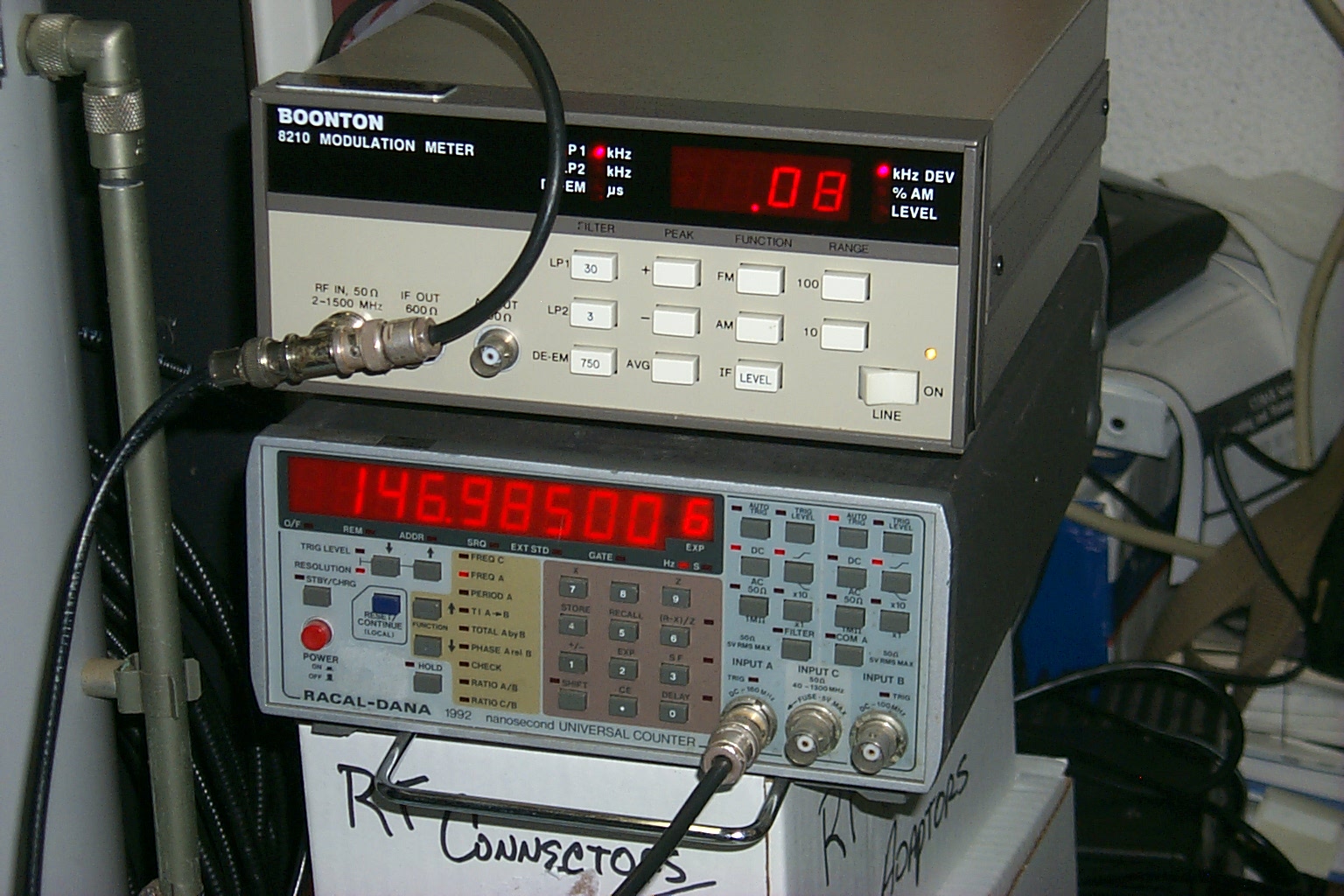
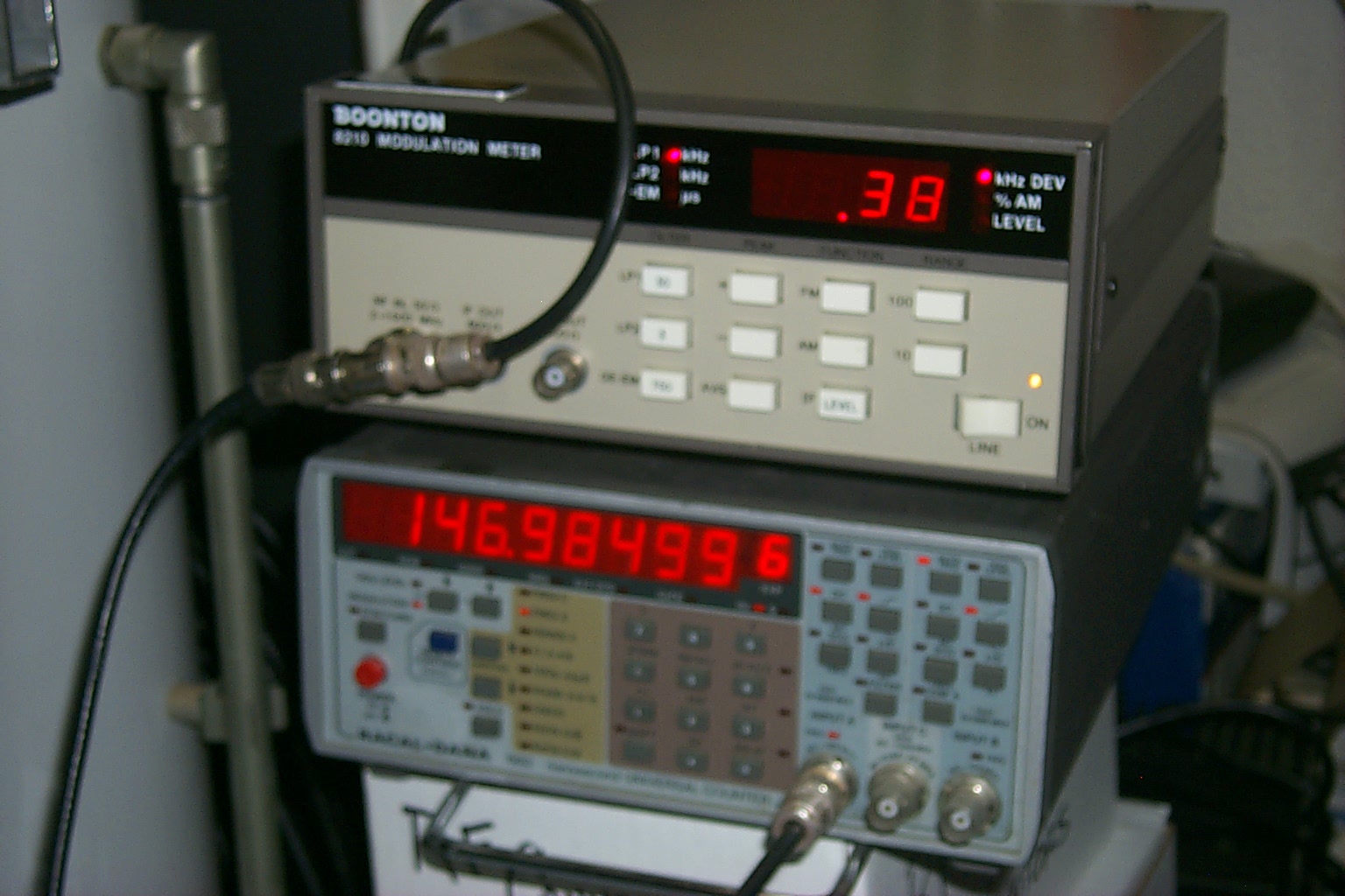
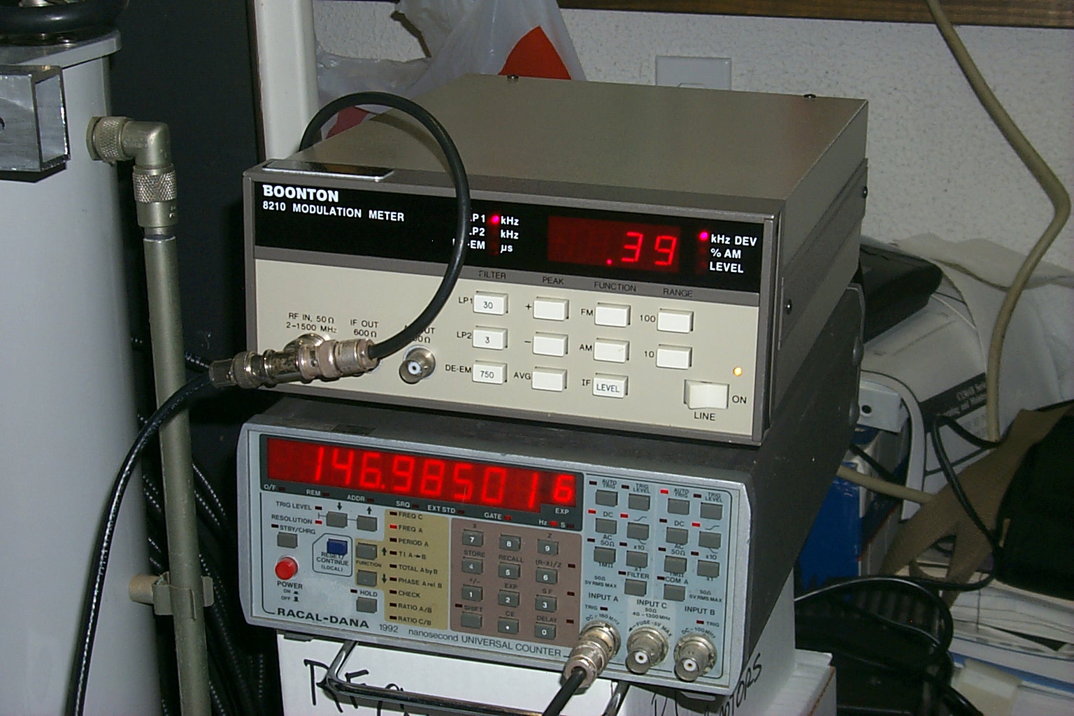
(click on images to enlarge)
Locked and Loaded
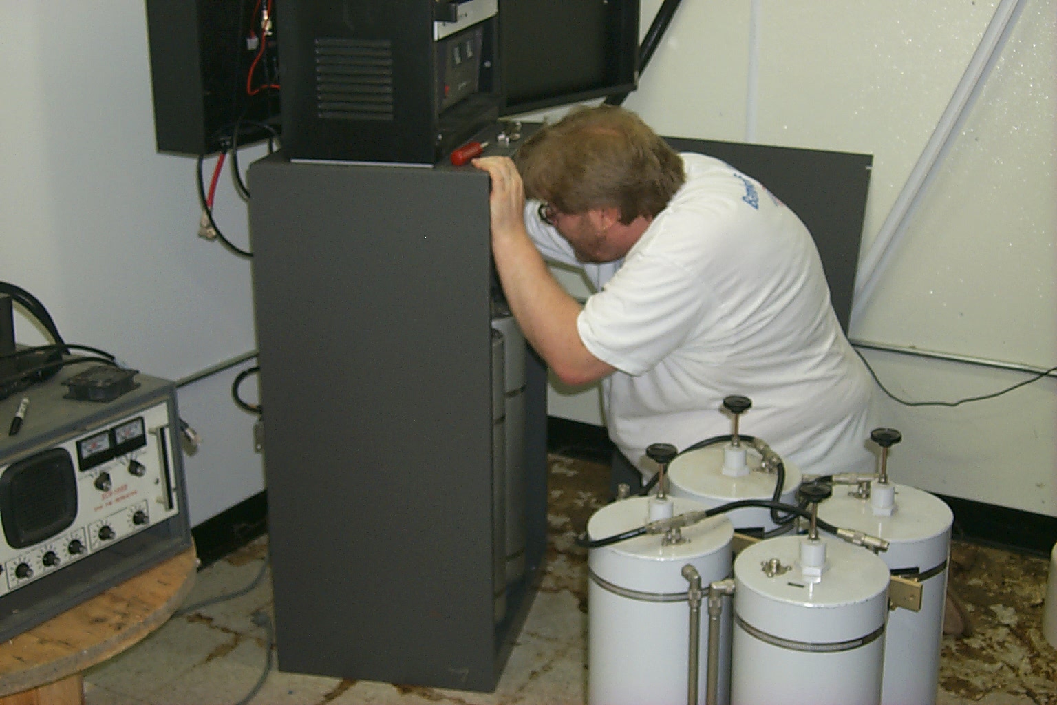
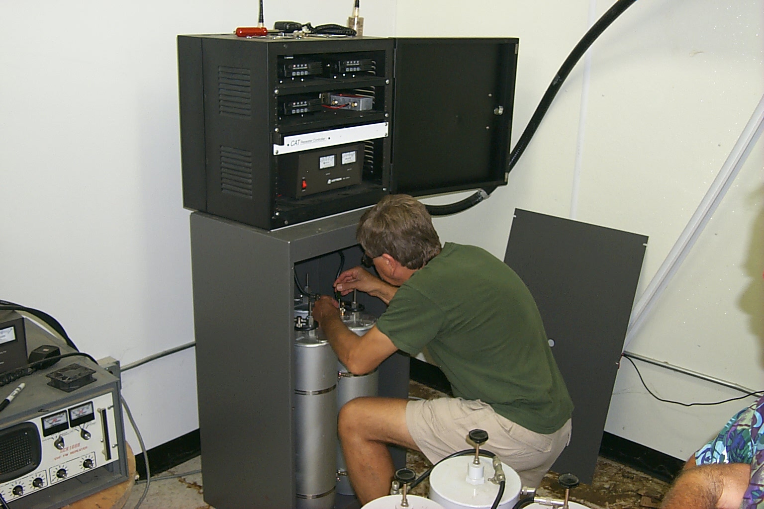
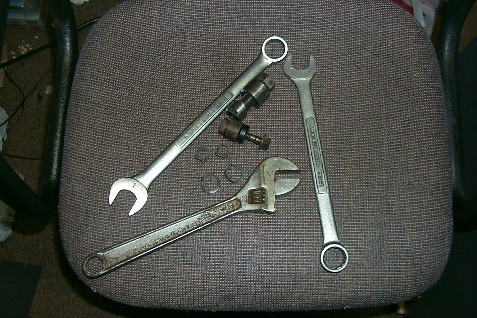
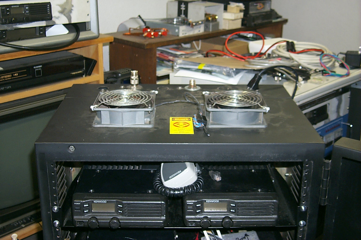
Once I hade everything adjusted and felt that that repeater was working well I packed everything into the Big Blue Beast and brought it down to the site so I could pull out the CAT-200/Icom gear and install the new S-Com 7K/TK-30 components. Once I arrived on site I setup all my test gear and tools.
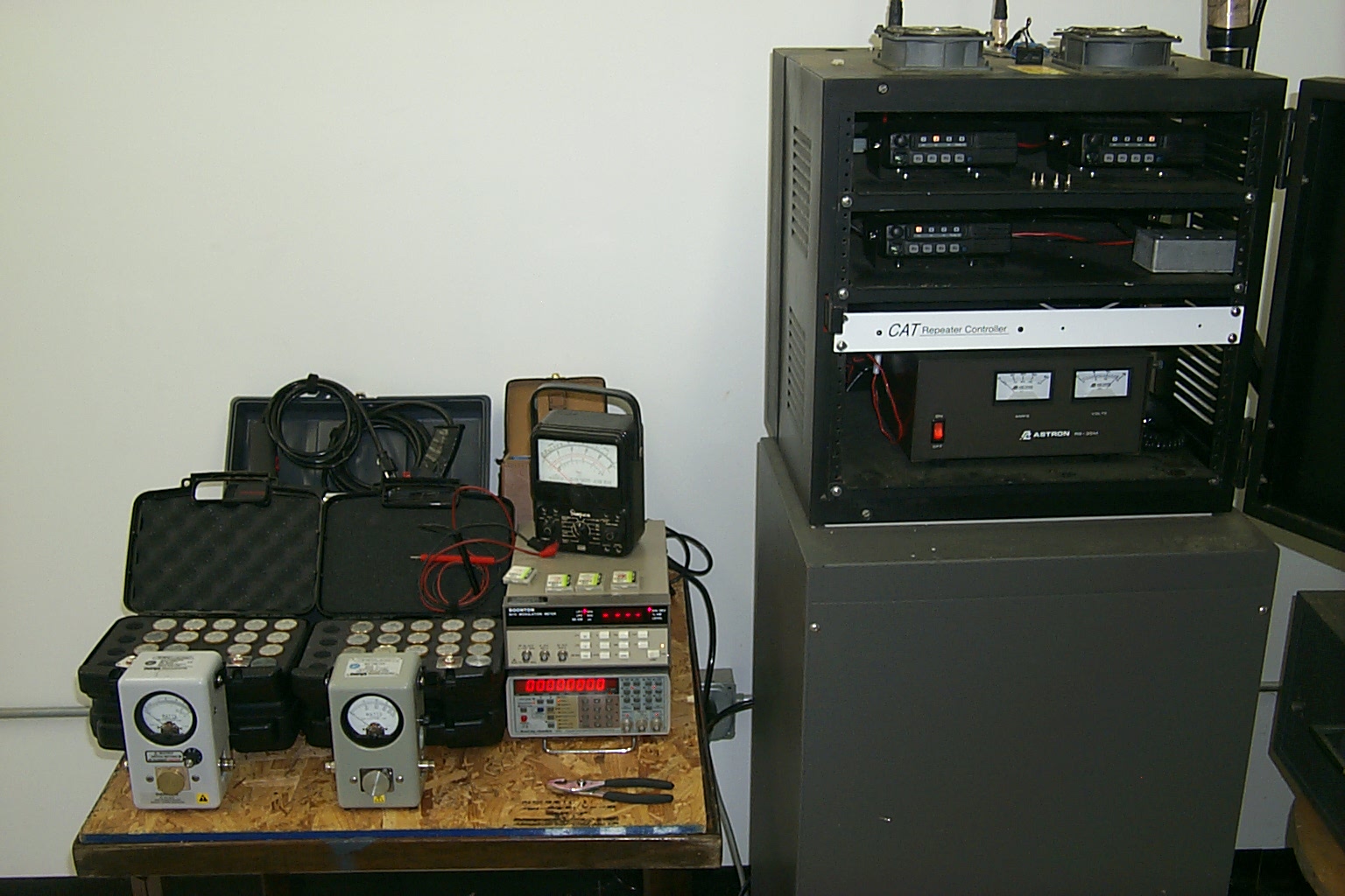
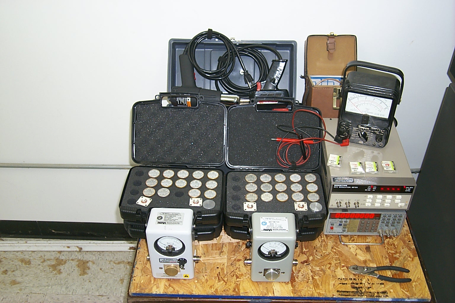
(click on images to enlarge)
Let the Rebuild Begun
I staged all the new repeater components and then started tearing down the old repeater.
(click on images to enlarge)
I split open the rack cabinet, then removed the CAT-200 controller, the shelves with the Icom radios, and the 35 Amp power supply.
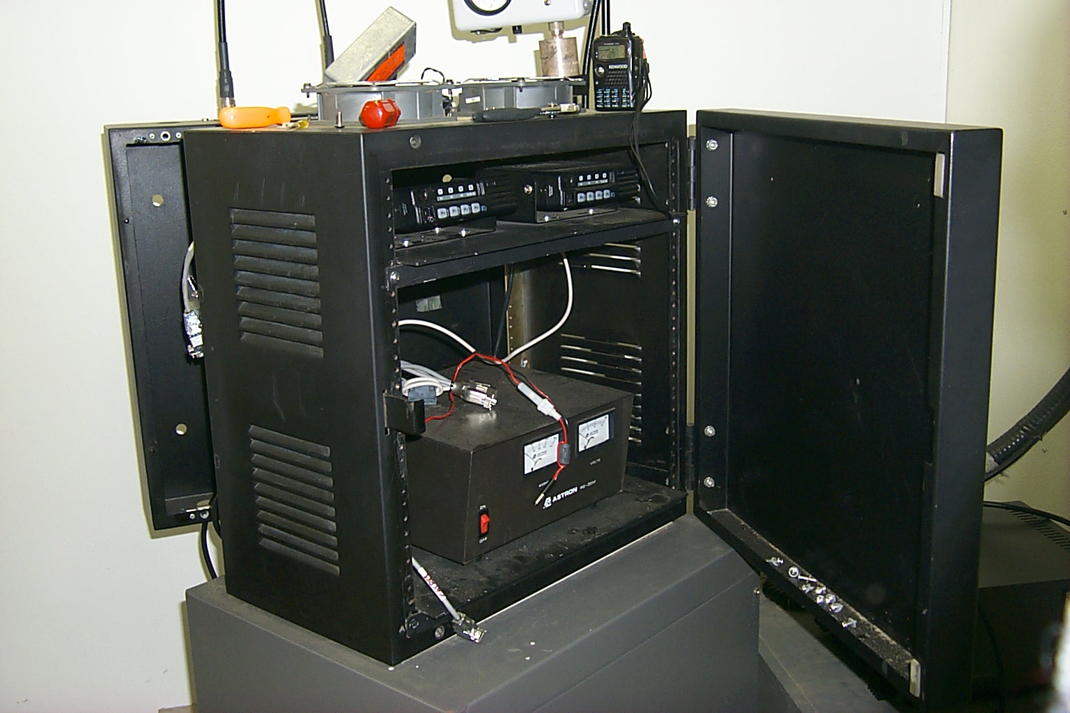
(click on images to enlarge)
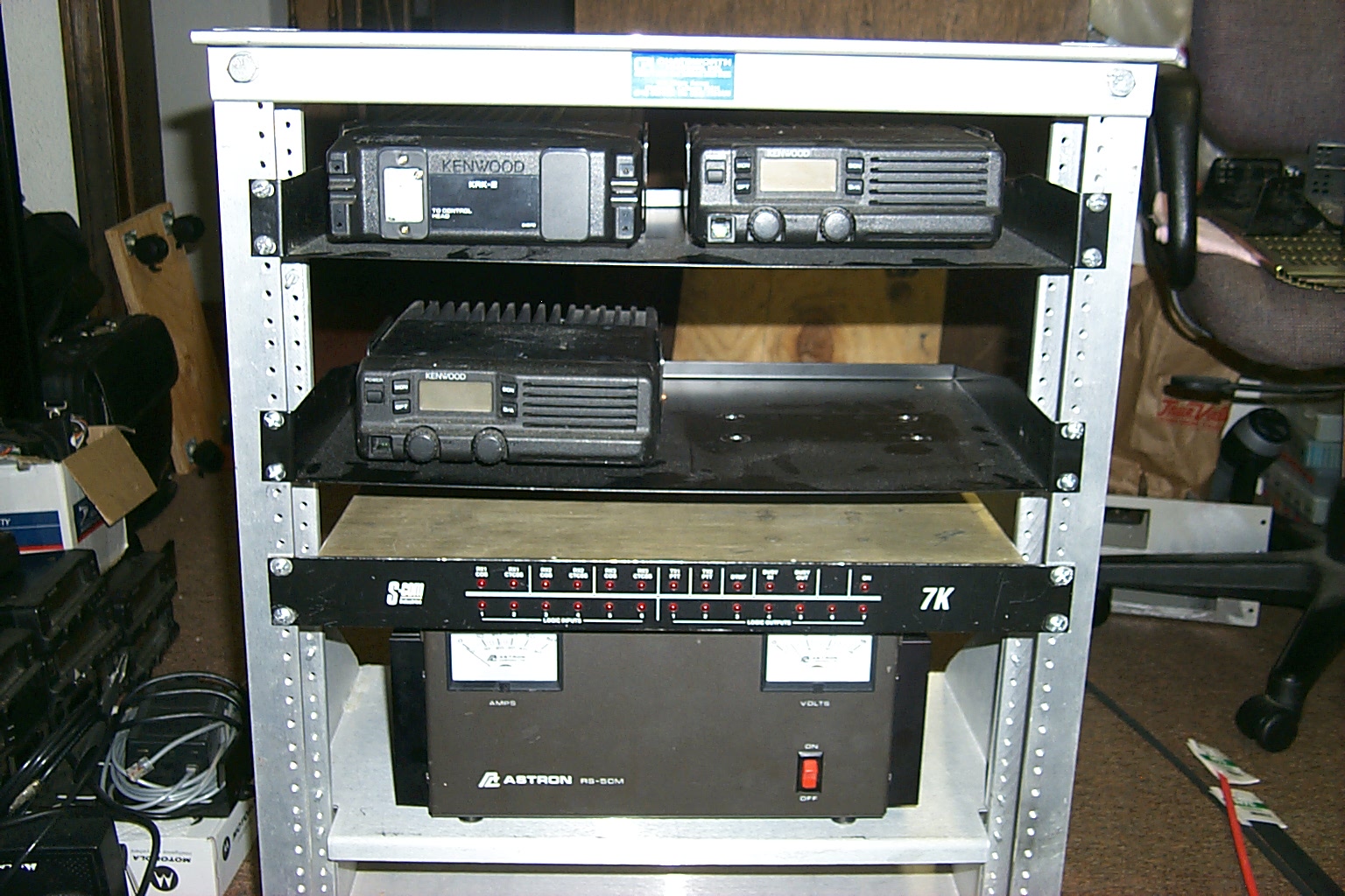
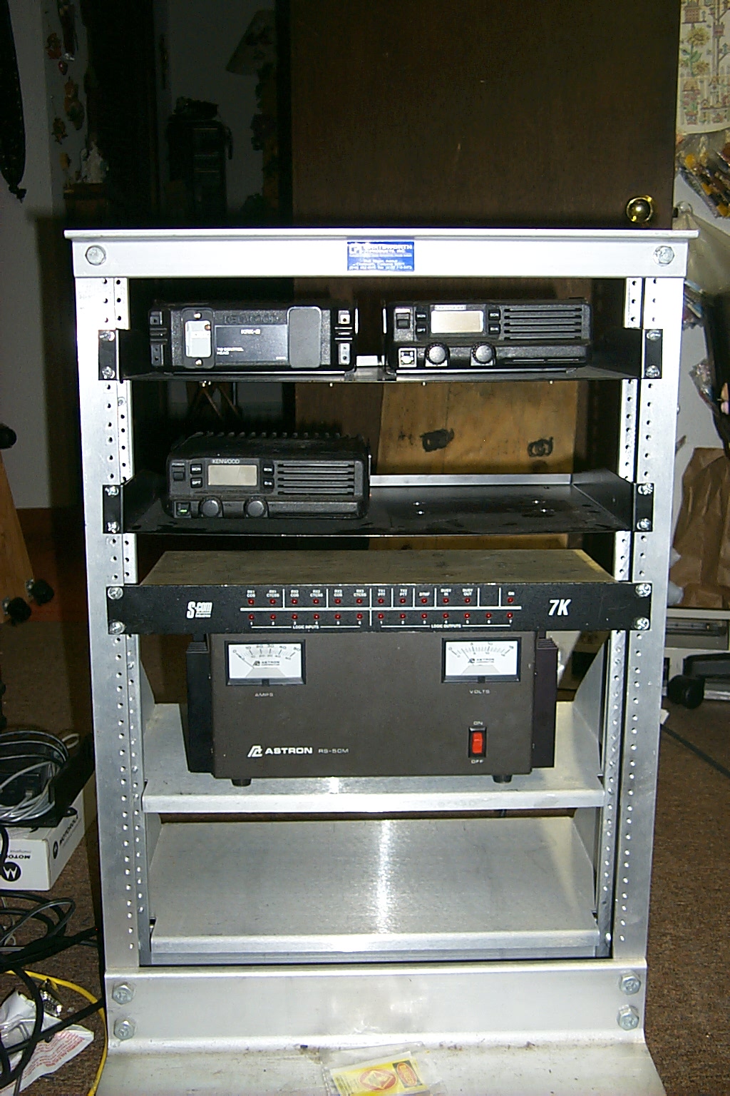
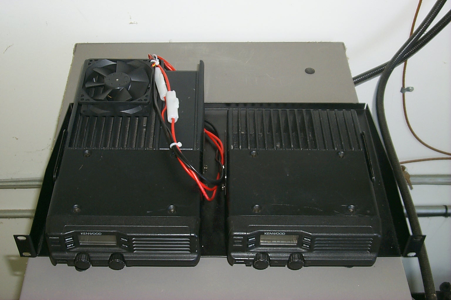
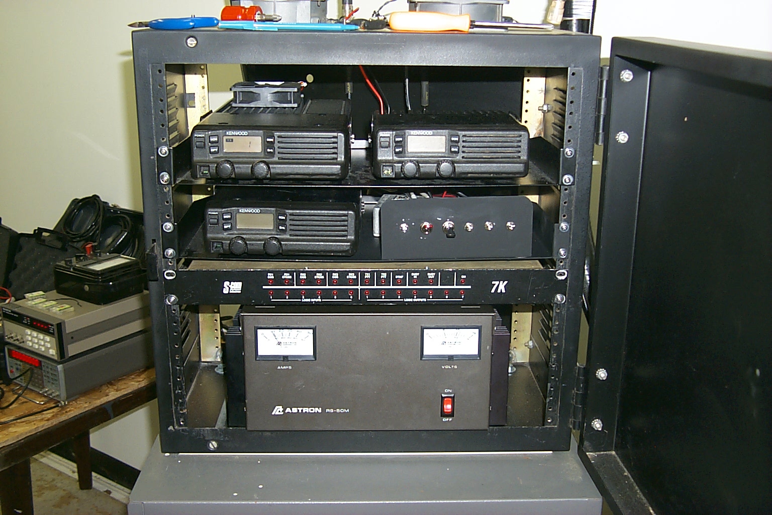
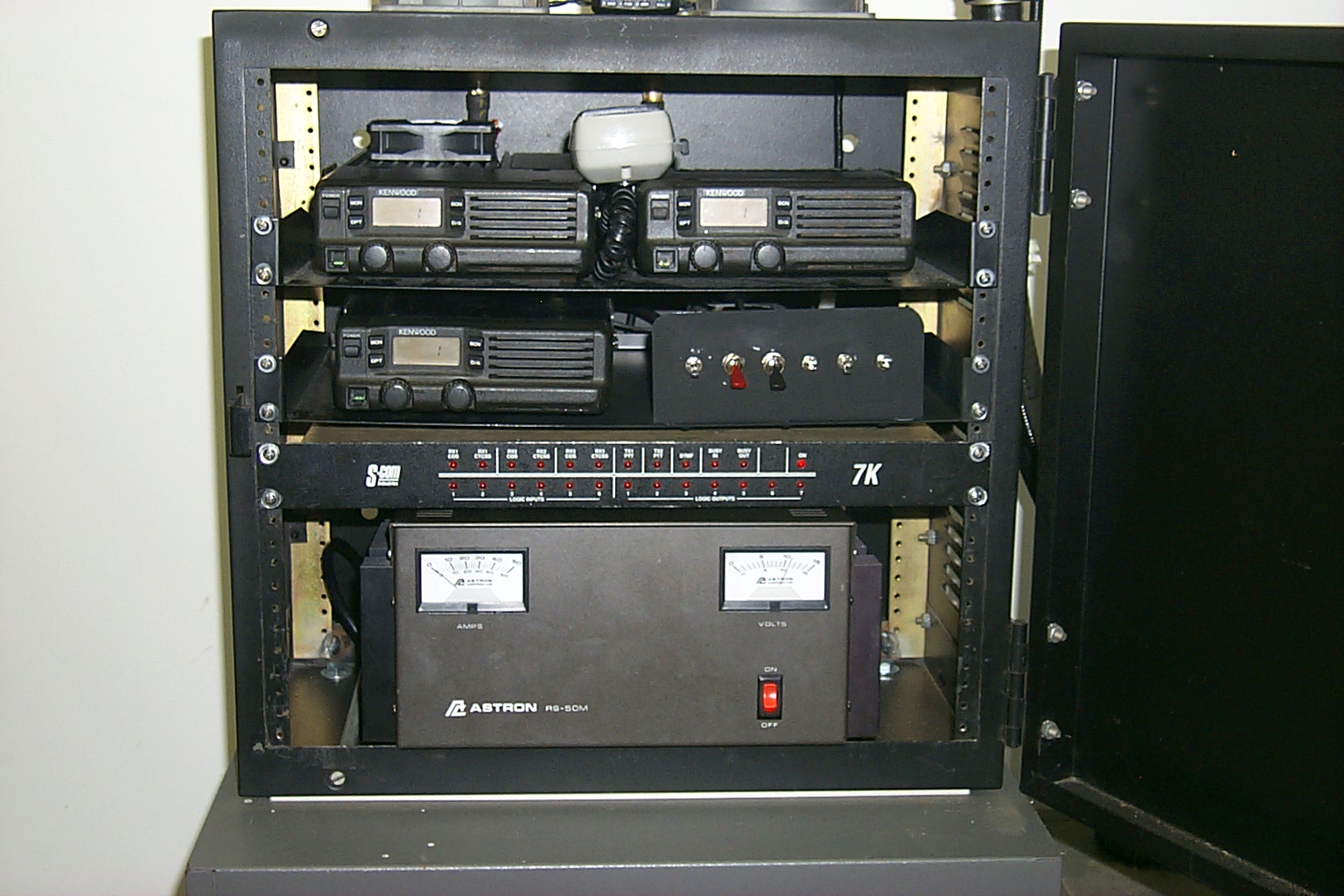
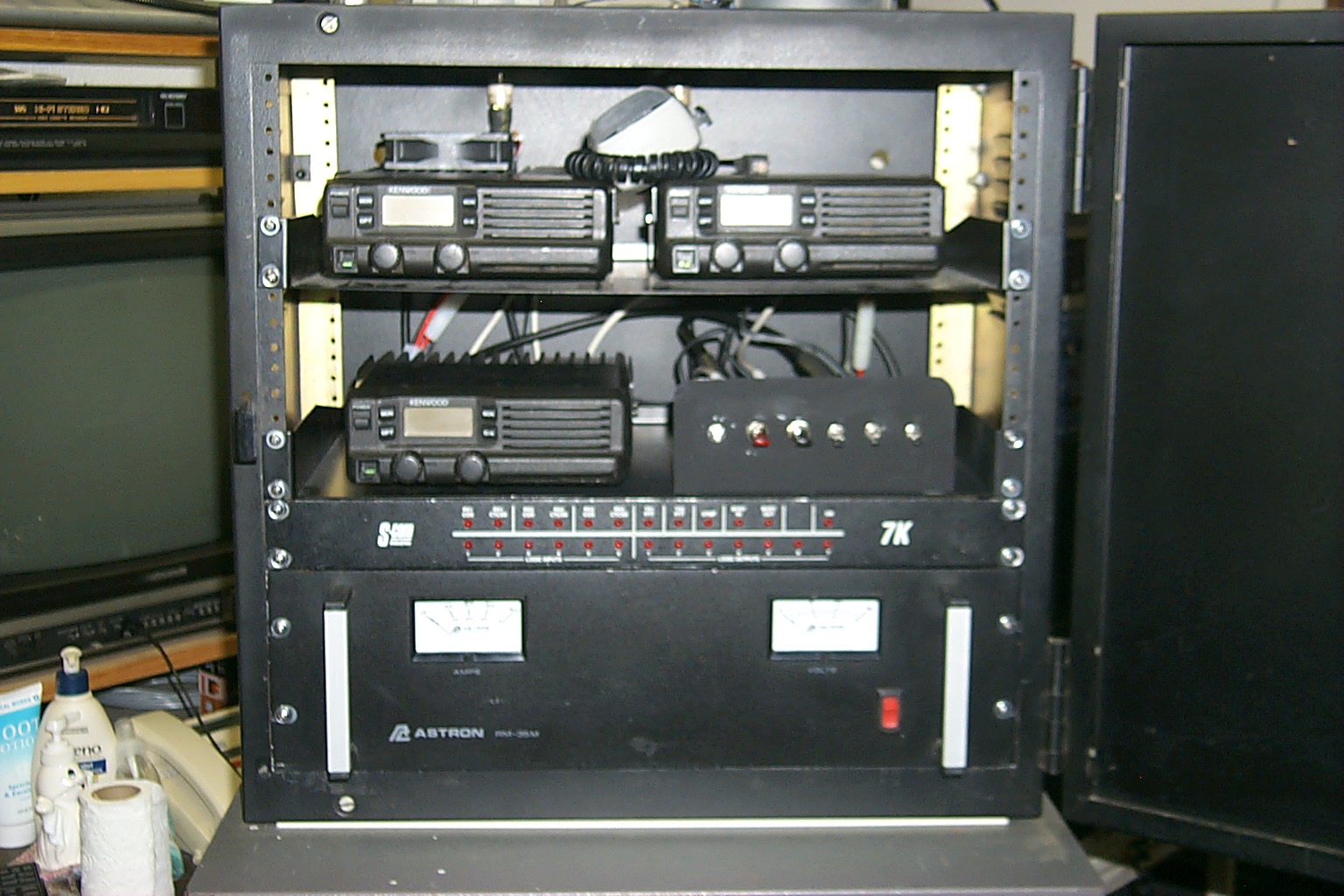
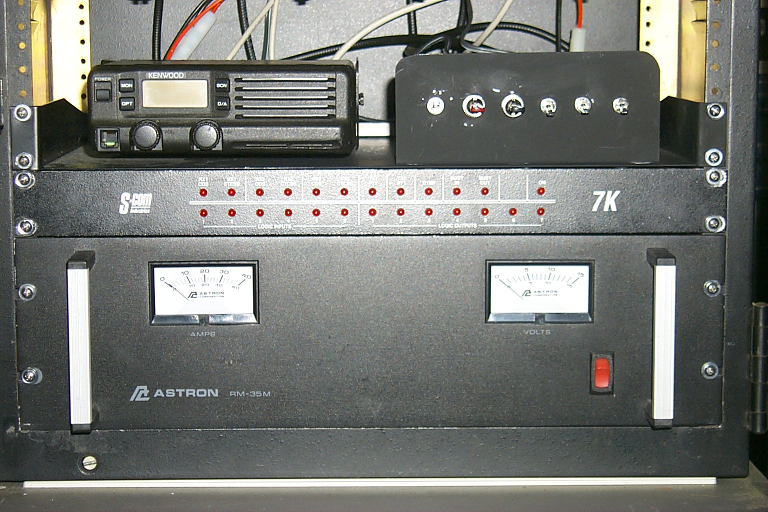
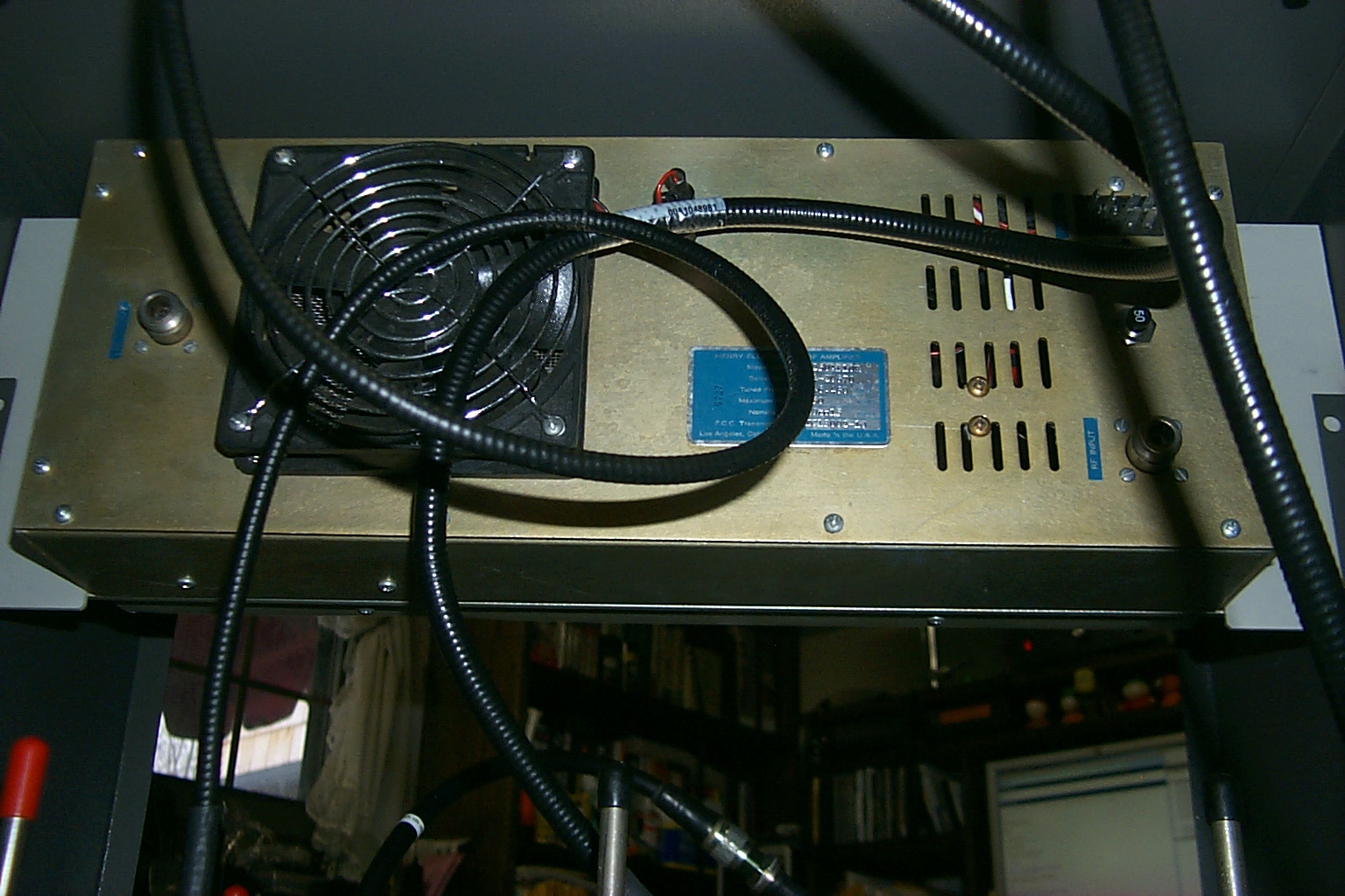
Next step was to mount the new 50 Amp power supply,
S-Com 7K controller, and the Kenwood radios.
(click on images to enlarge)
What, No Coffee?
Right about now Bill KA1JNP was talking about
how he should have gotten up off the couch and brought me a "Cup"...
... He never did.
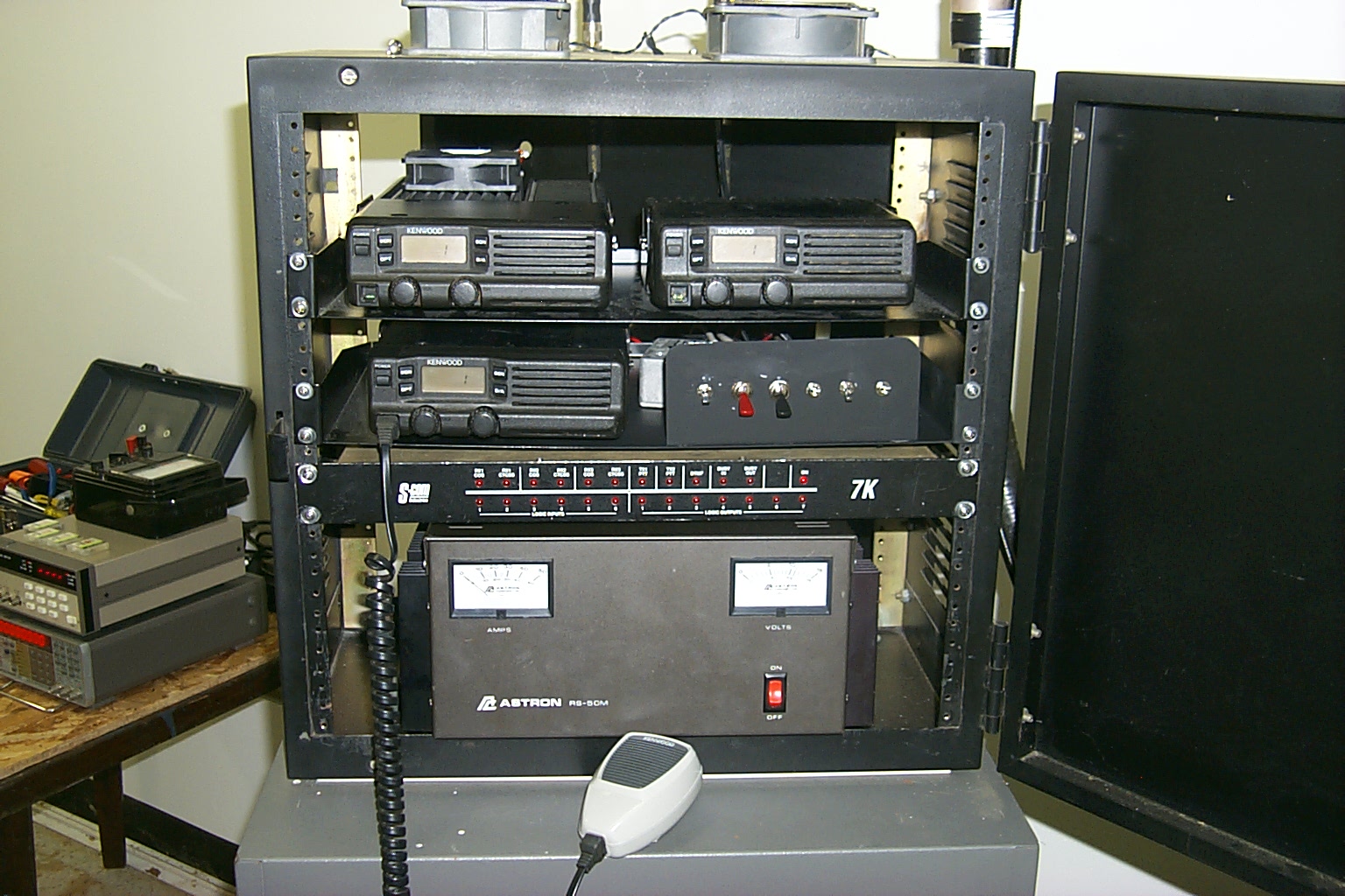
These last few photos show the completed repaired / rebuilt 146.985 repeater
on the air. Bill KA1JNP was one of the first stations to check in from his
couch using his HT on low power with a rubber duck... With in minutes of
flipping the power switch on there were a half dozen stations checking into
the repeater and providing signal reports.
I guess it is working...
(click on images to enlarge)
That did not last long... (one week later)
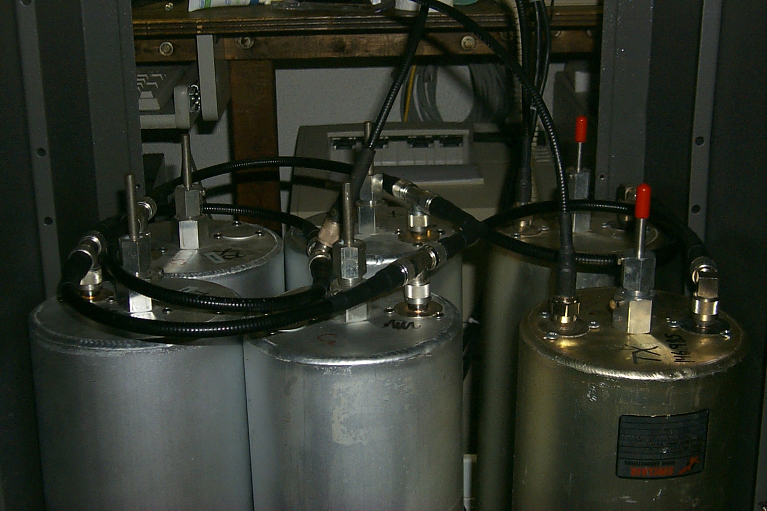
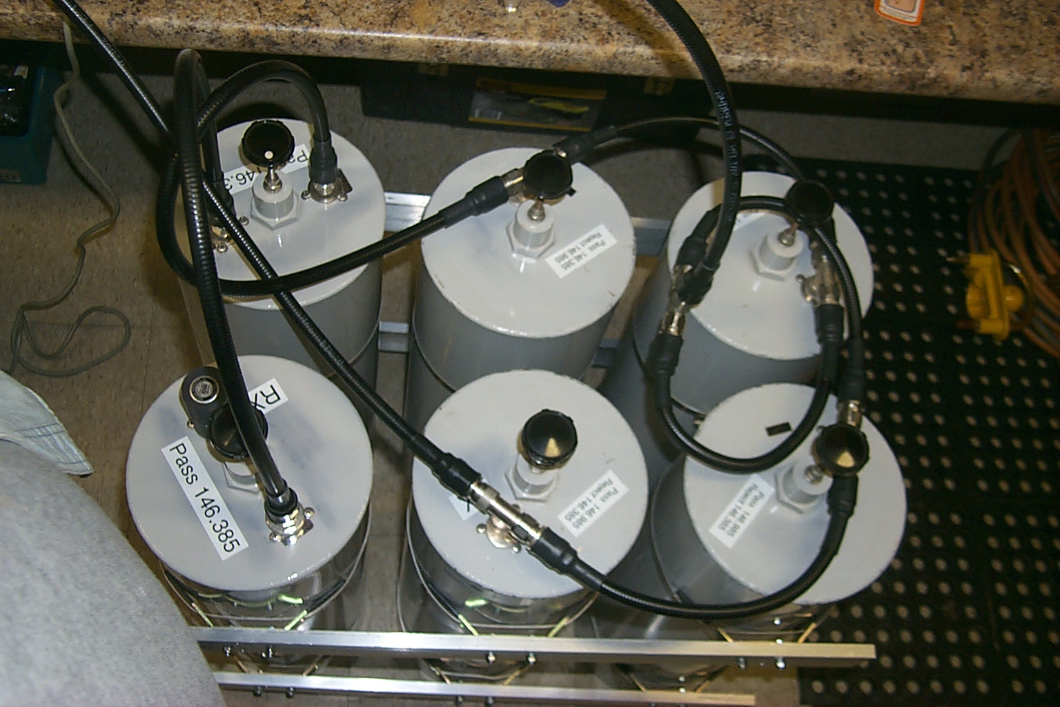
The upgraded .985 went on the air Saturday afternoon and was working well however I was not happy with the low transmit power output and took I ride back to the site the following Monday evening to investigate what was wrong. It turned out to be a problem with the FSJ-1 jumper cable between the transmitter and the duplexer, there was something wrong with the cable that was causing the TX power to fold back and also cause the transmitter to get into the receiver.
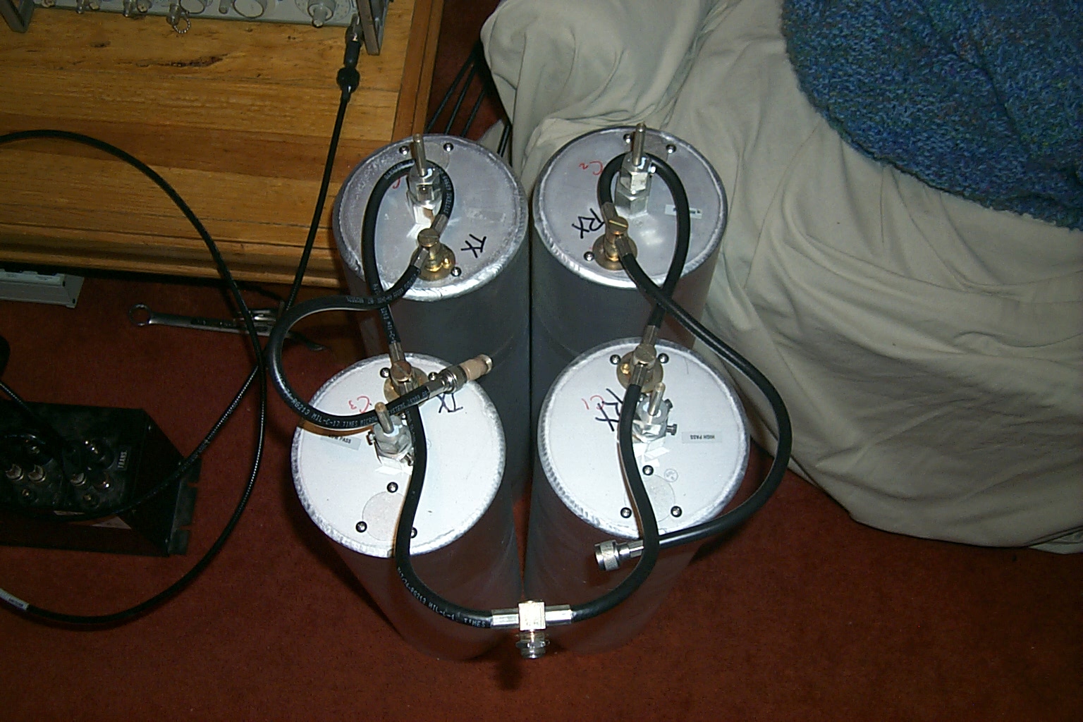
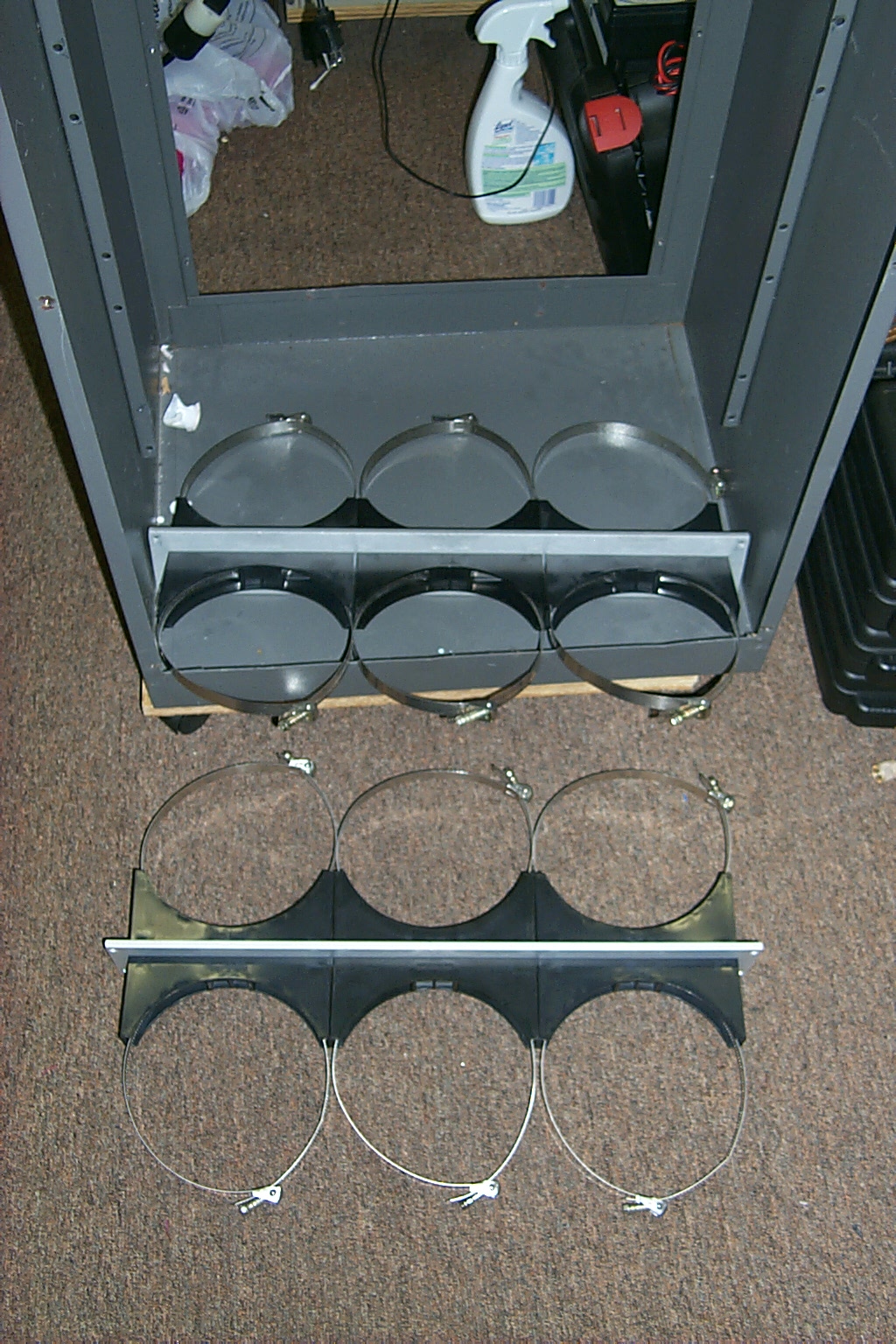
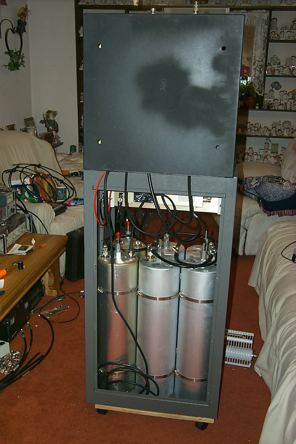
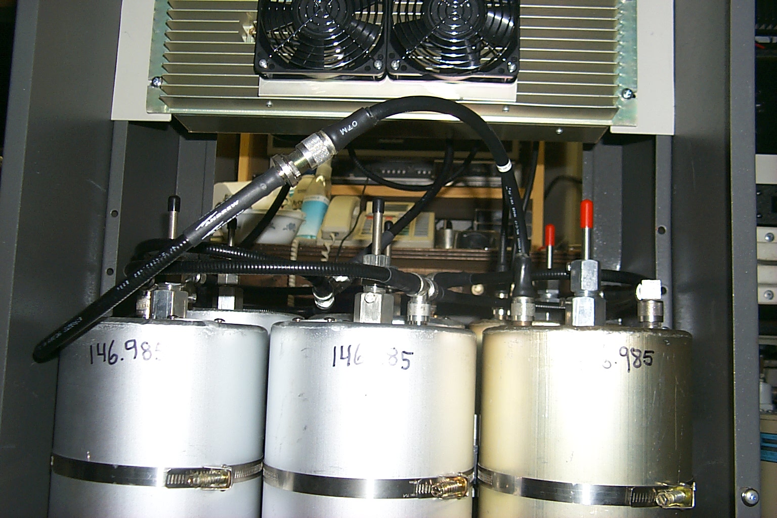
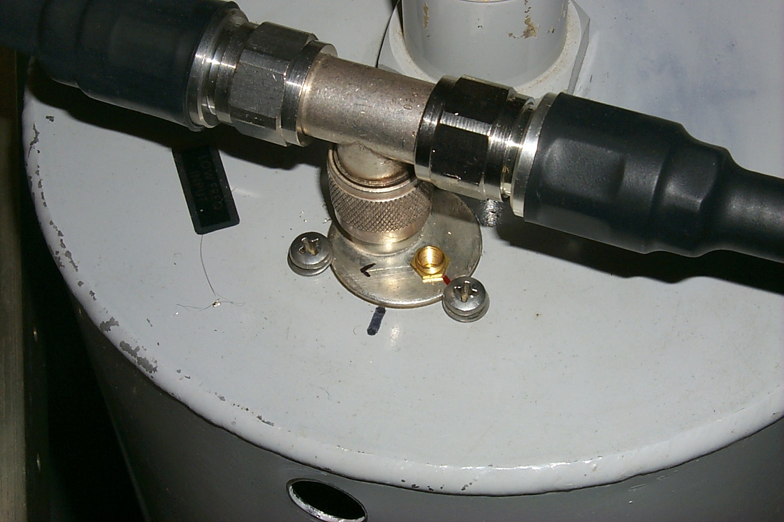
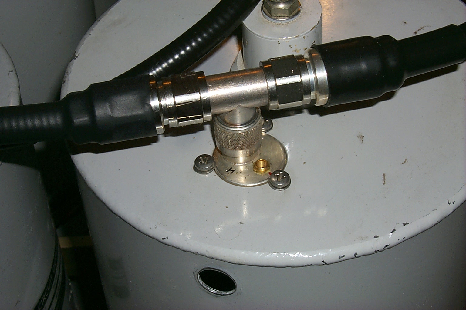
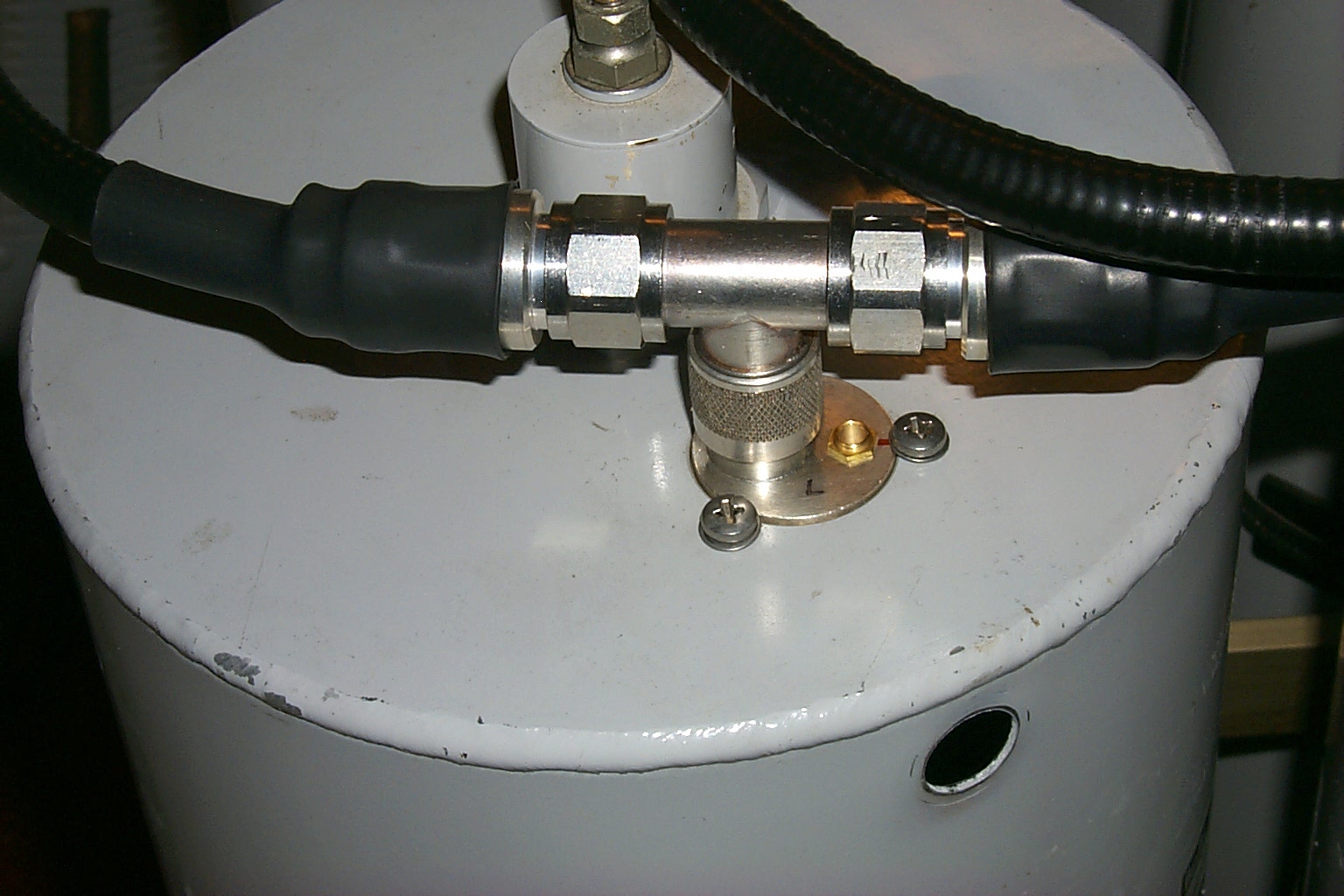
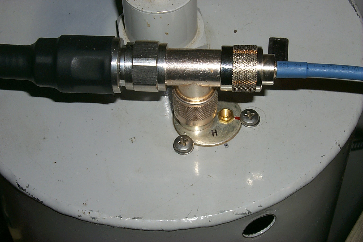
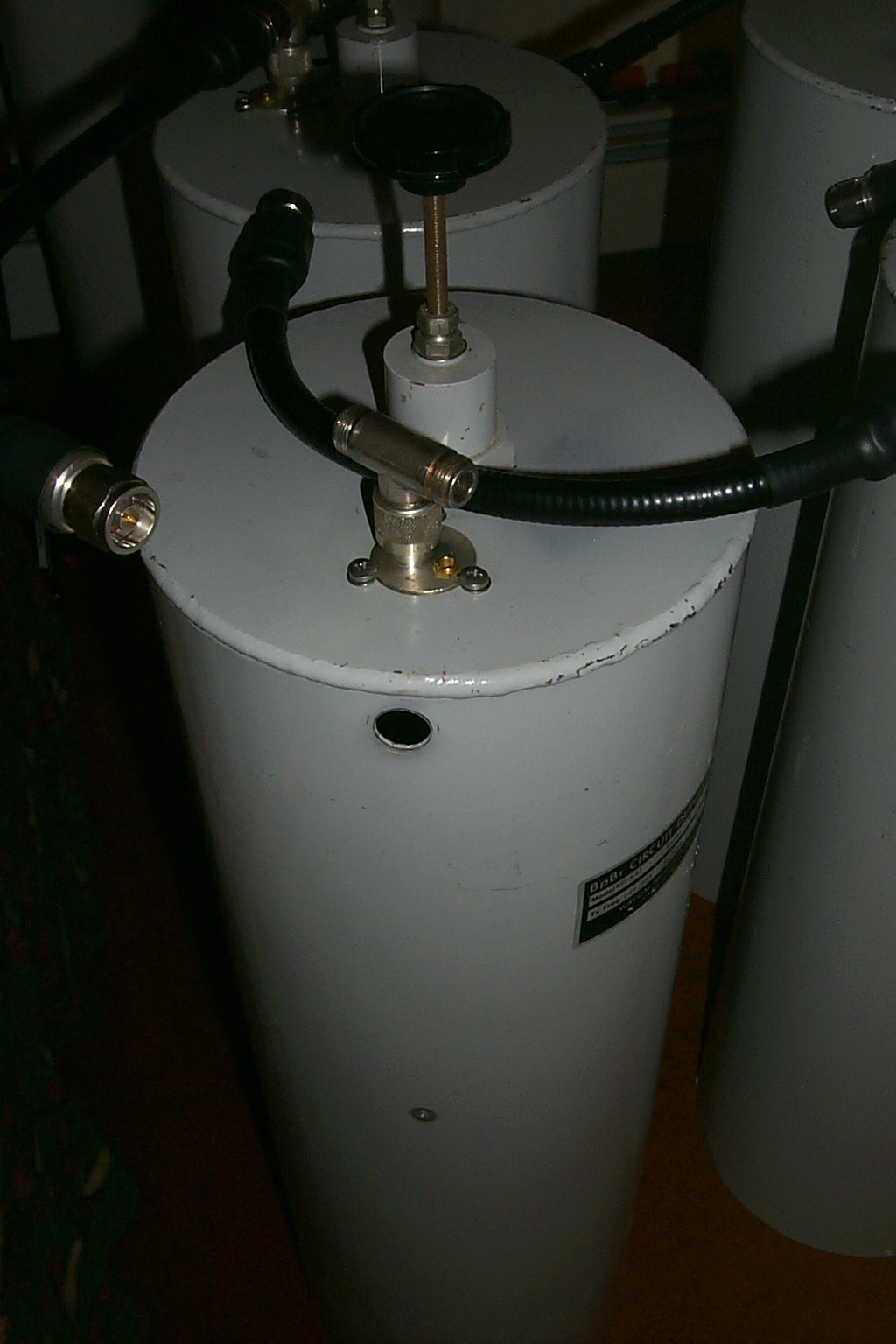
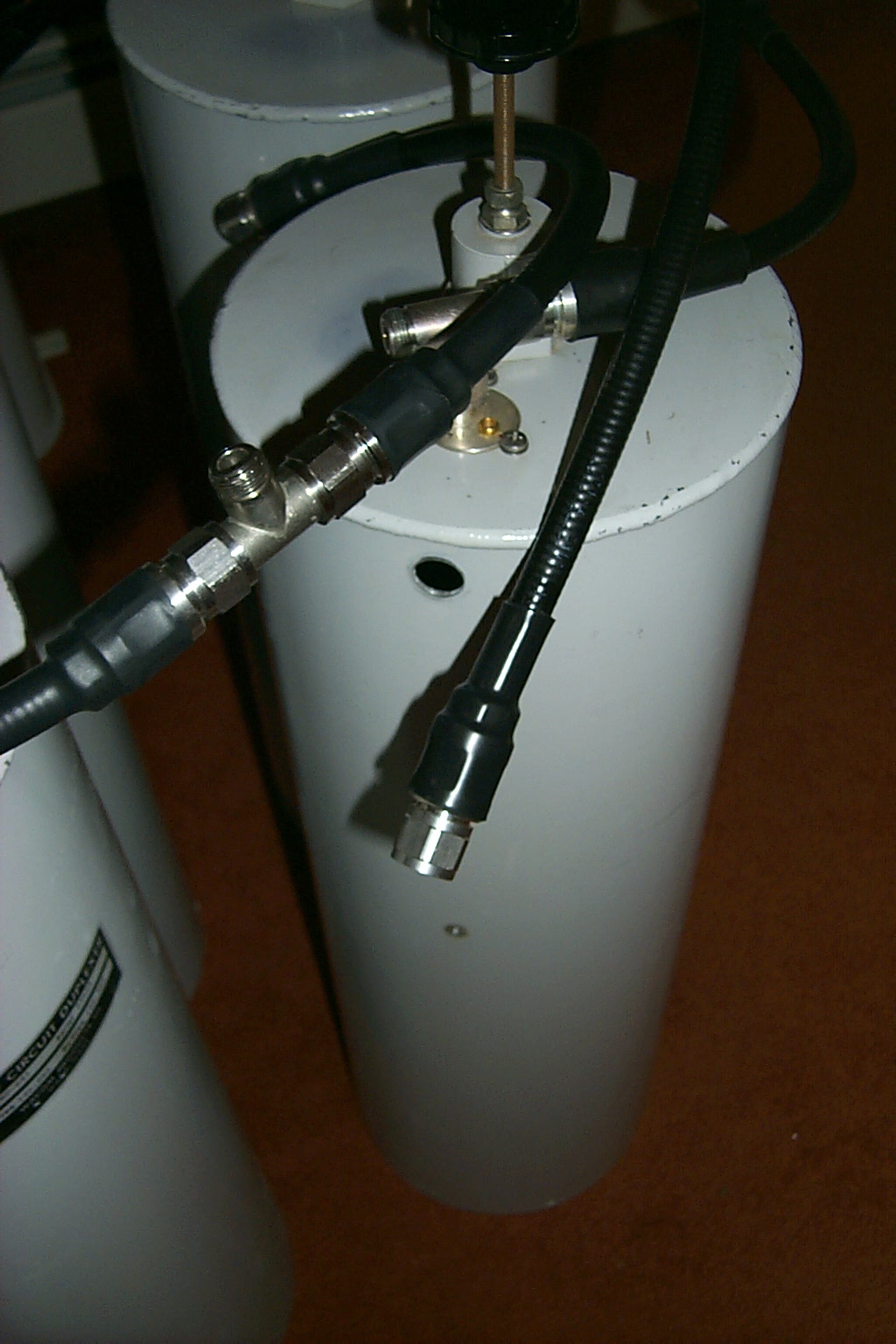
In these three photos you can see the smaller FSJ-1 heliax cables that enter into the bottom duplexer cabinet and connect to the factory Sinclair phasing harness that were causing the problems.
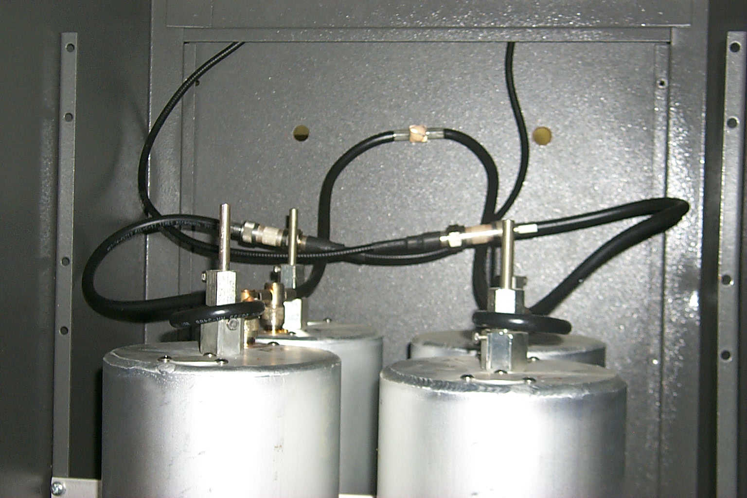
(click on images to enlarge)
Pack it up!
I decided to load the newly upgraded repeater into the Big Blue Beast, drag it back to Lincoln, and diagnose / repair the problems in the comfort of my radio shack.
Rebuild it again?
Once I got the repeater back home and started taking things apart I decided that it was time to upgrade the duplexer now that I had the new Kenwood upgrade in place. I had wanted to add two additional band pass cavities and make a new phasing harness using Andrew FSJ-2 heliax like I had already done on the 147.075 and 147.390 repeater projects. I already had the cable, connectors, and extra cavities so all I need to do was roll up my sleeves and make it happen...
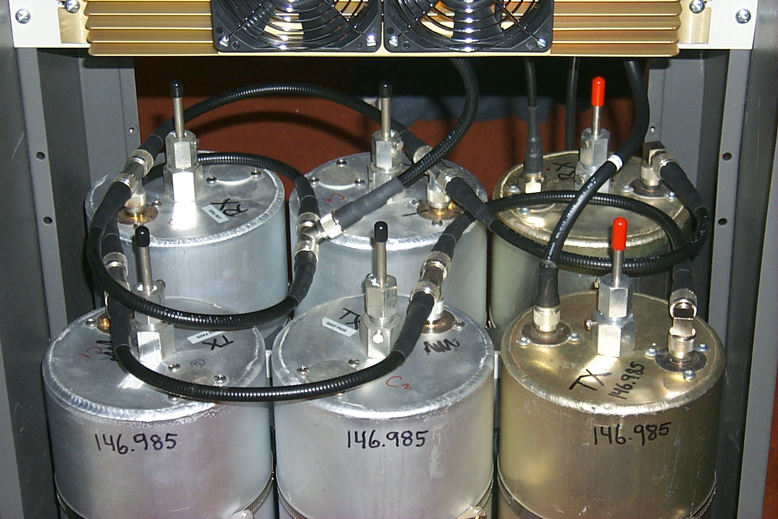
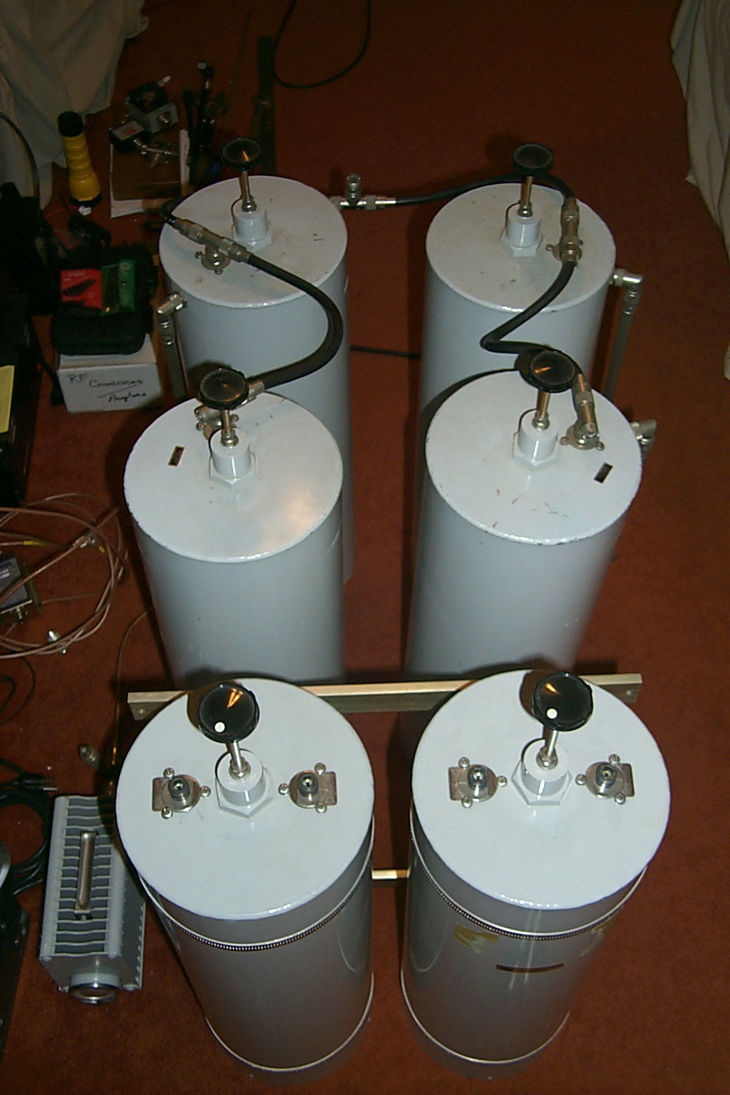
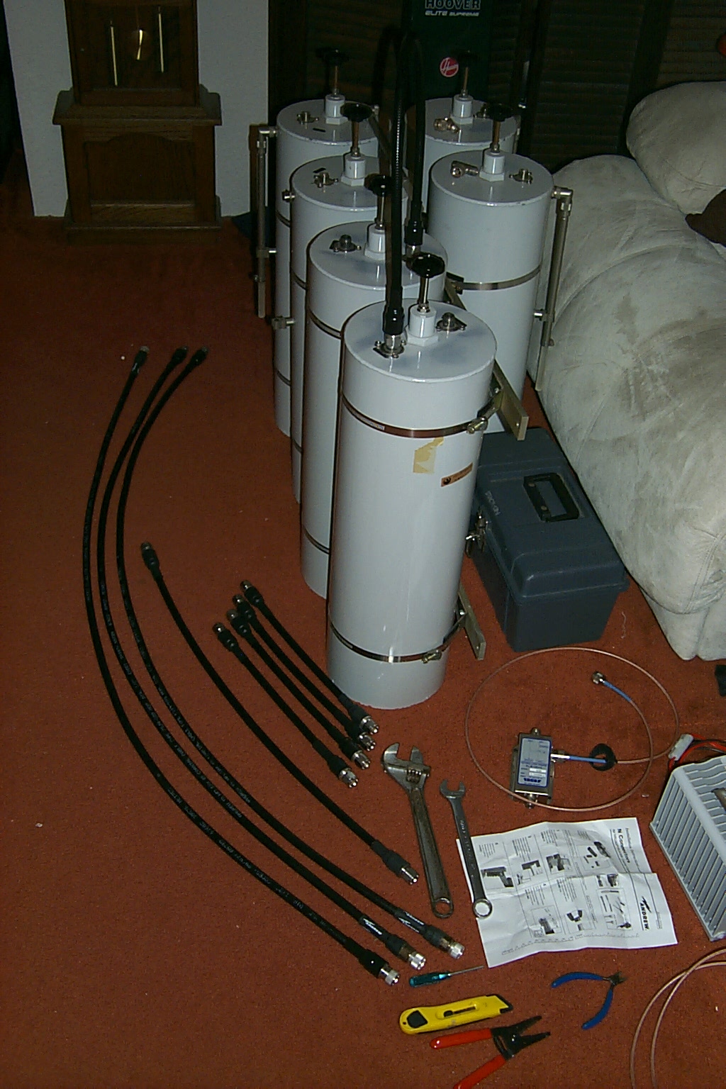
Six is better than Four... Right?
The factory Sinclair phasing harness was most likely a VHF high and had crimped connectors which I did not like. I would remove that and replace it with one of my custom made FSJ-2 phasing harnesses while adding the two additional band pass cavities.
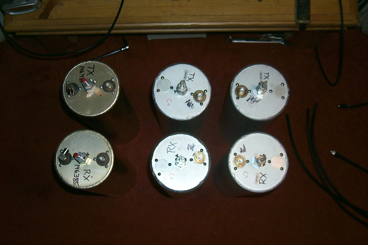
(click on images to enlarge)
The bottom duplexer cabinet with the existing four cavity duplexer had enough room for two additional cavities and as I took the mounting hardware apart I found out that the bars were already drilled out for six cavities, all I had to do was unbolt everything move the existing mounts out to the ends and then add the additional mounting hardware for the two new cavities in the middle.
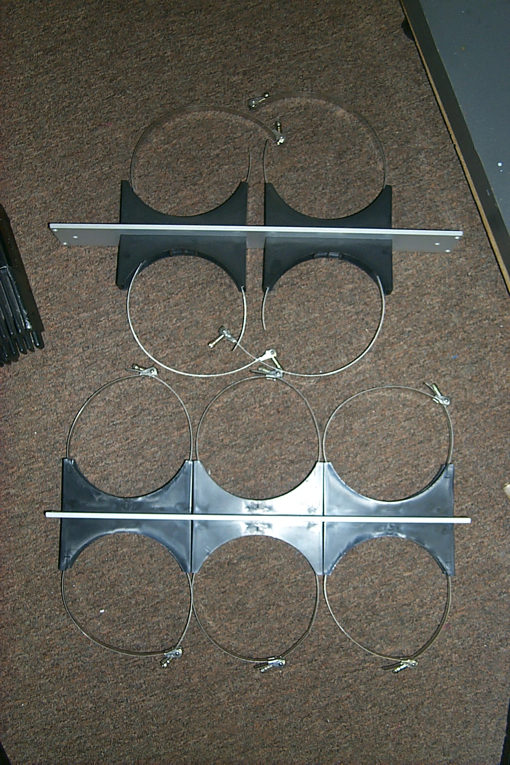
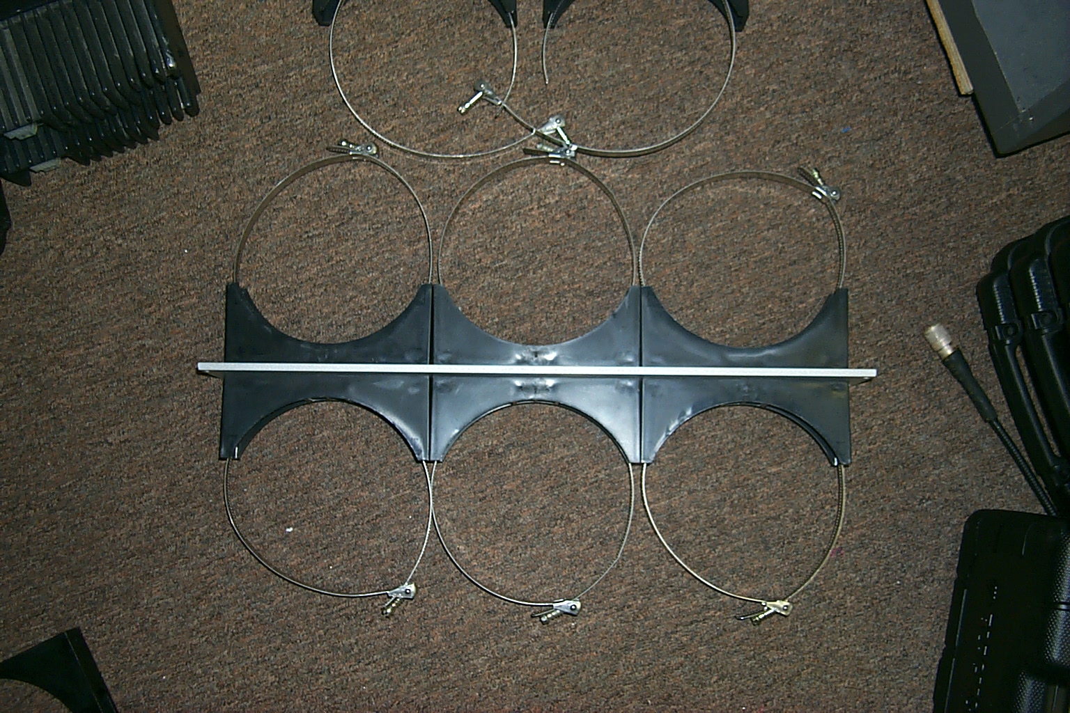
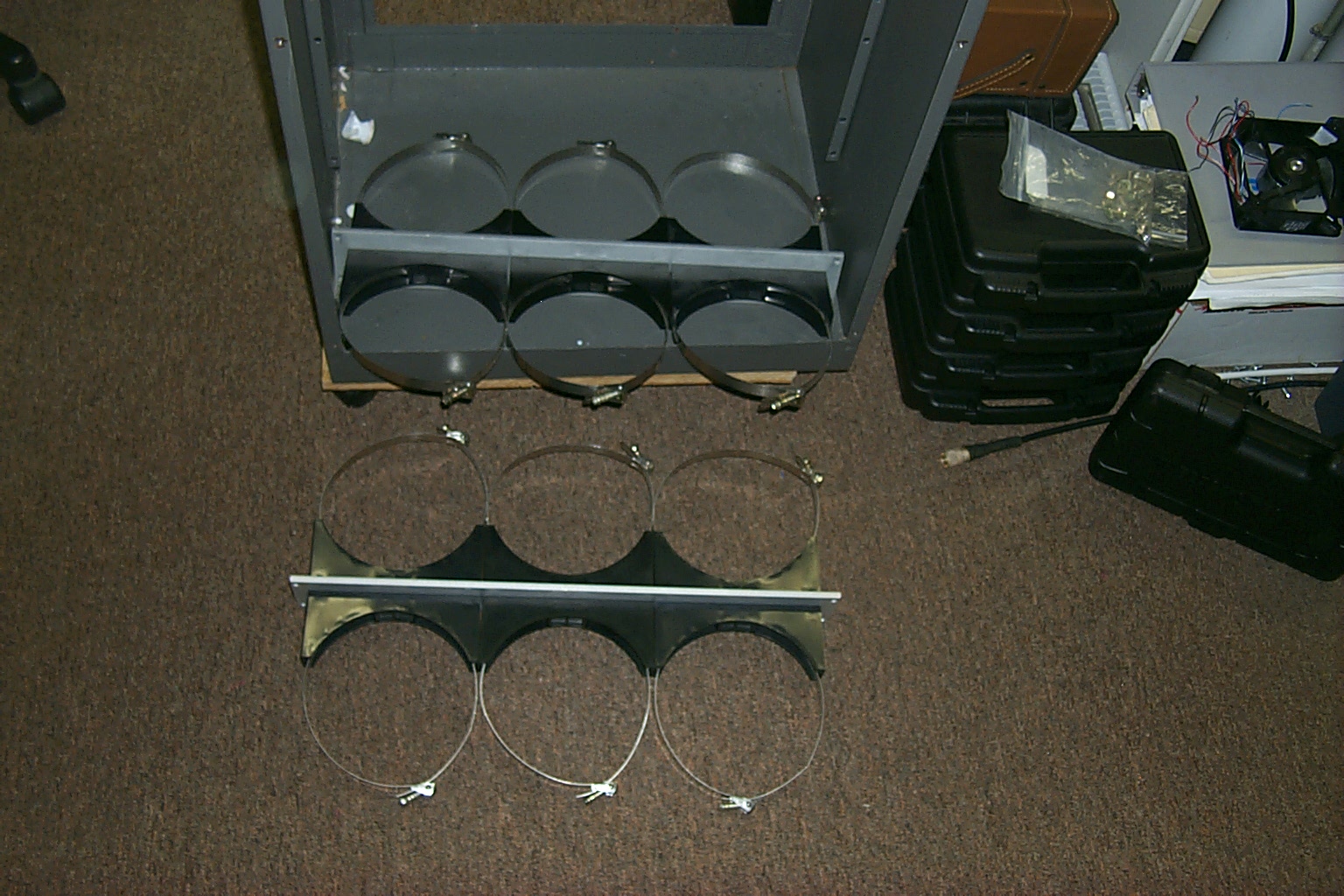
(click on images to enlarge)
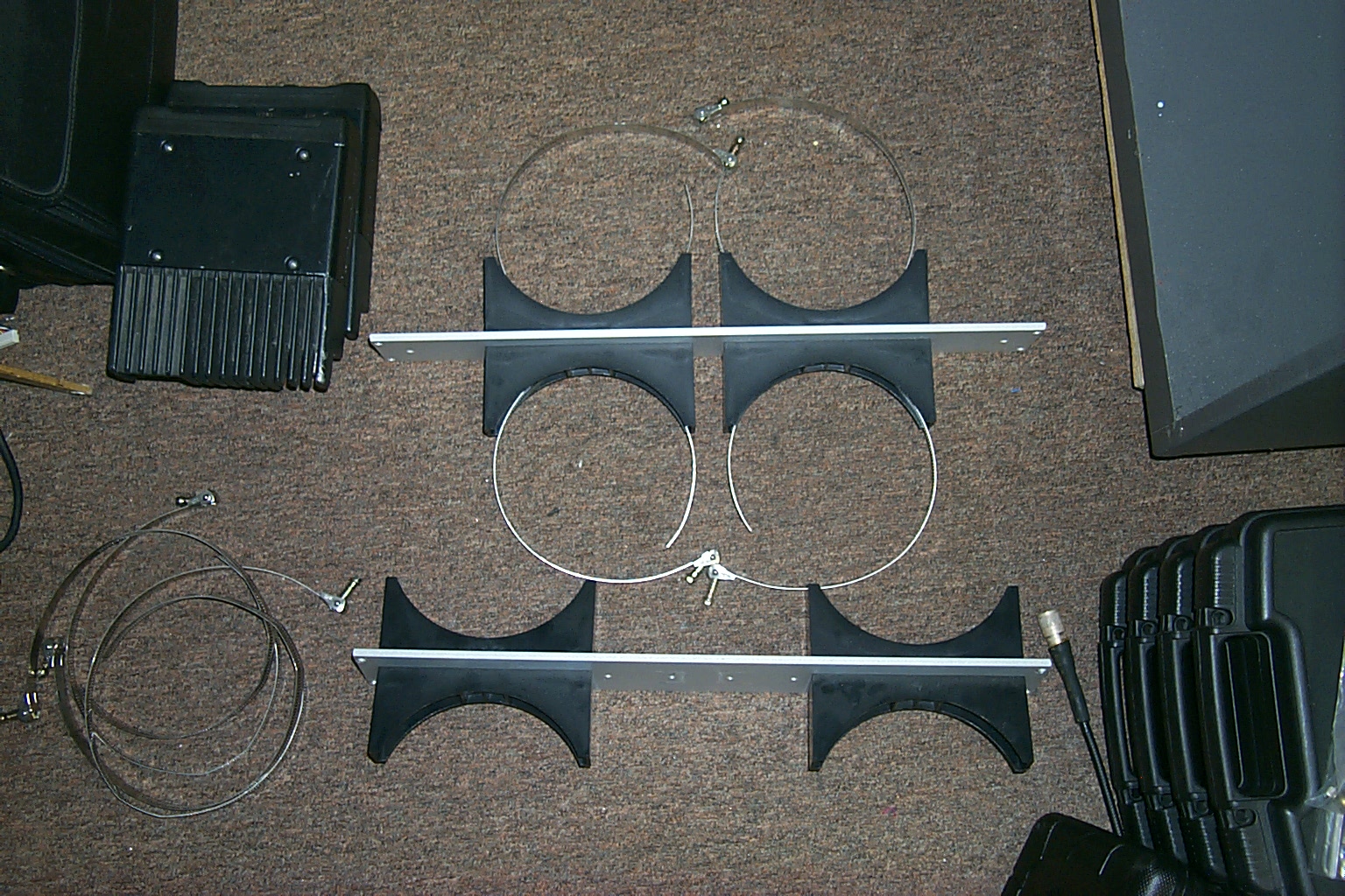
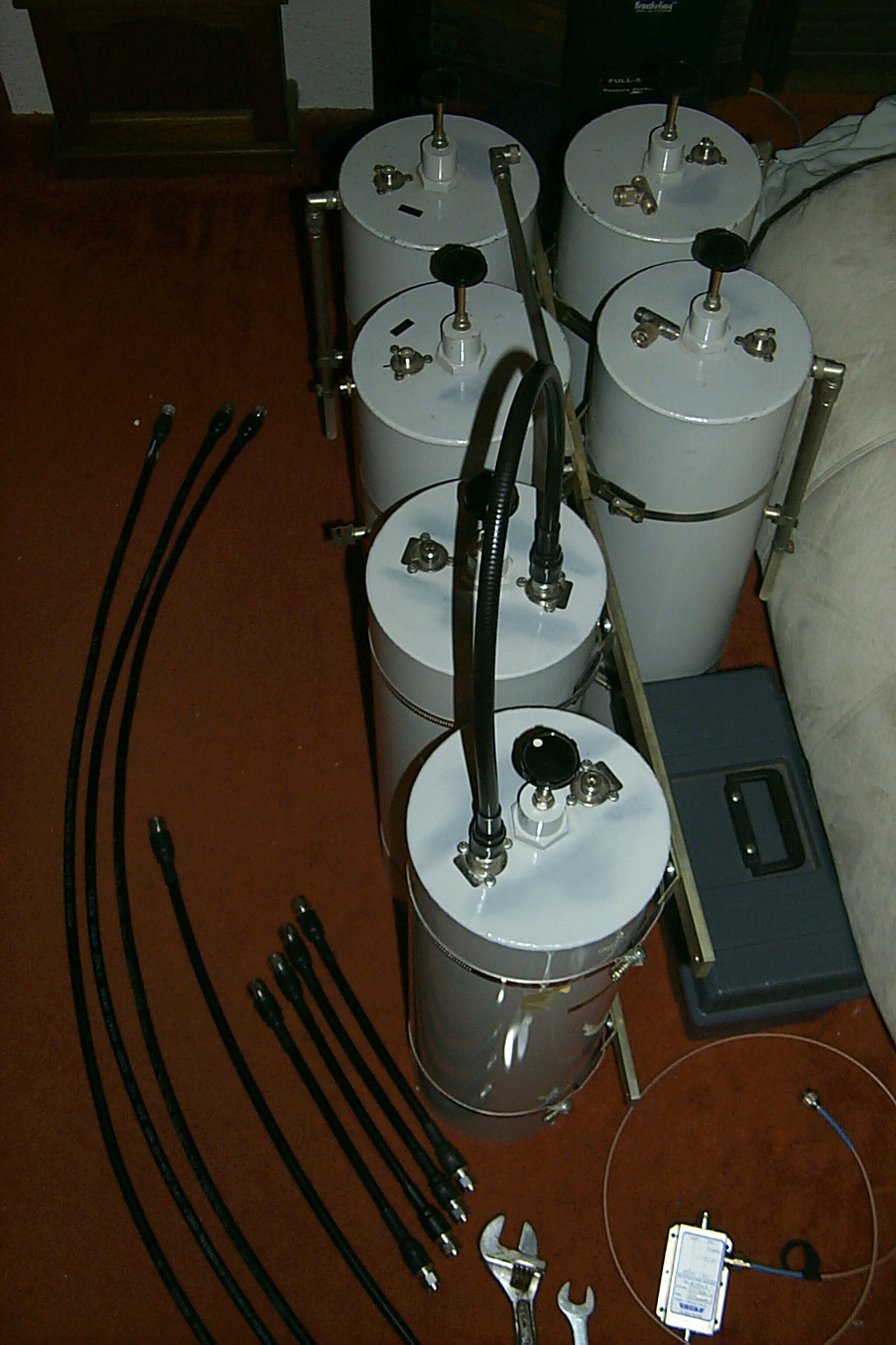
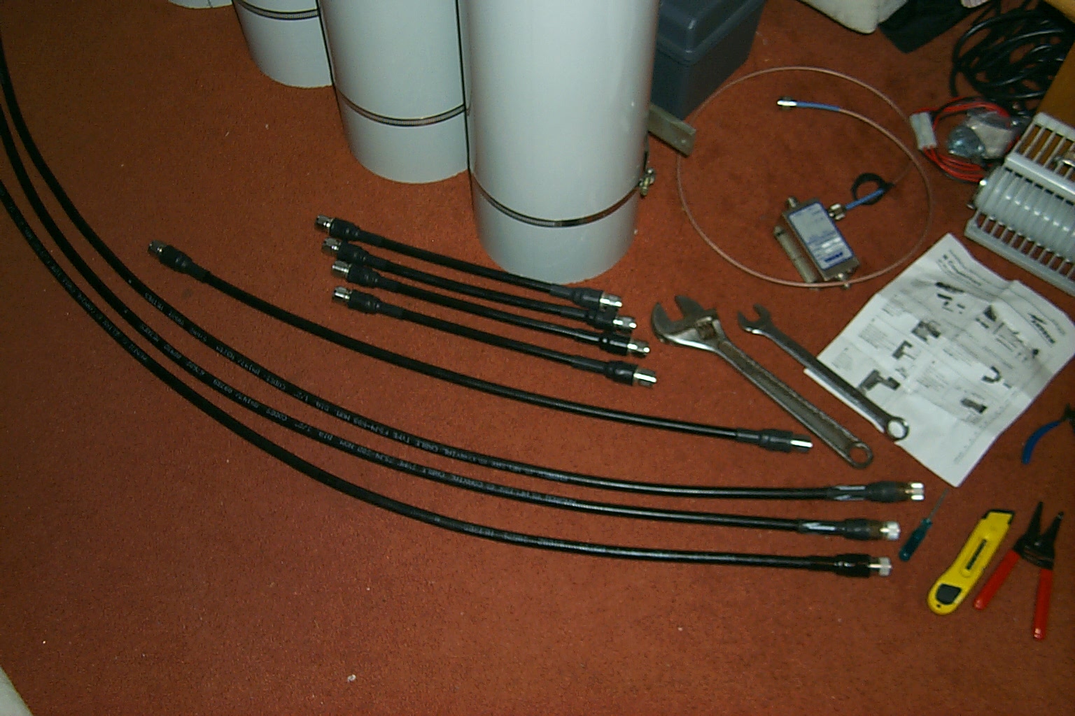
Time to make some more of those cables
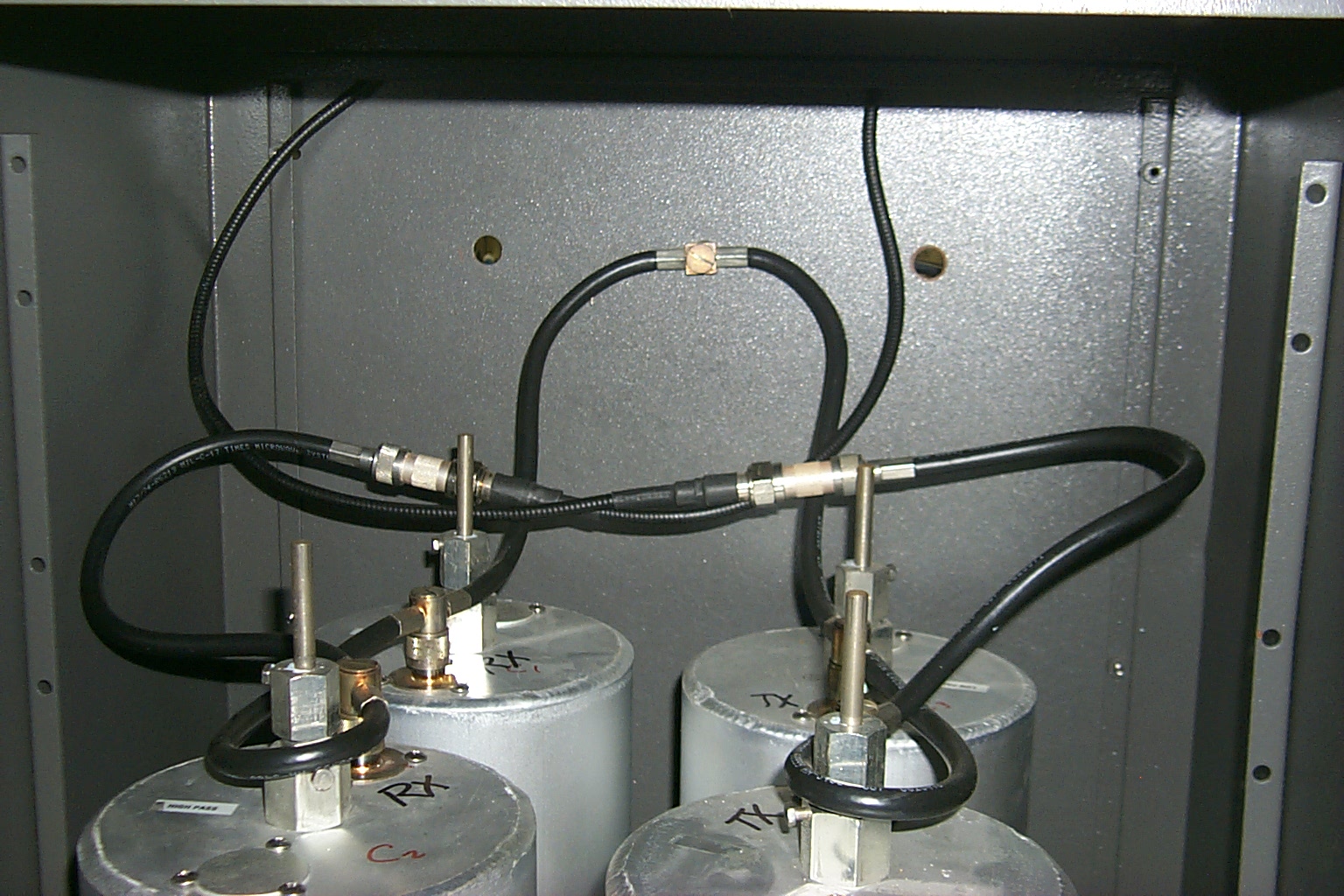
With the mounting hardware ready for the upgraded six cavity duplexer I started working on the new phasing harness. In the photos below you can see the old factory cable with the crimped connectors and my new heliax jumpers ready to build my custom phasing harness.
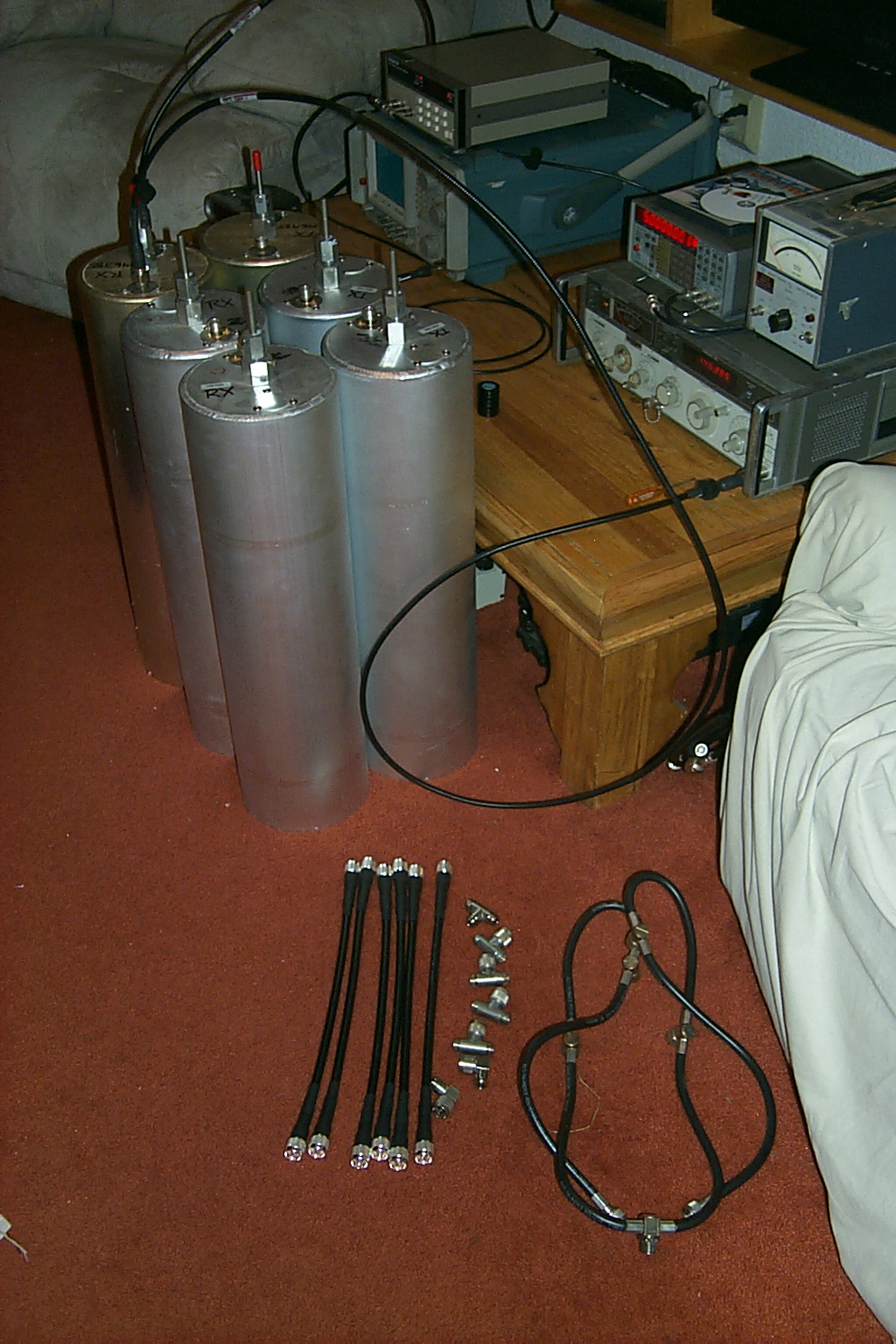
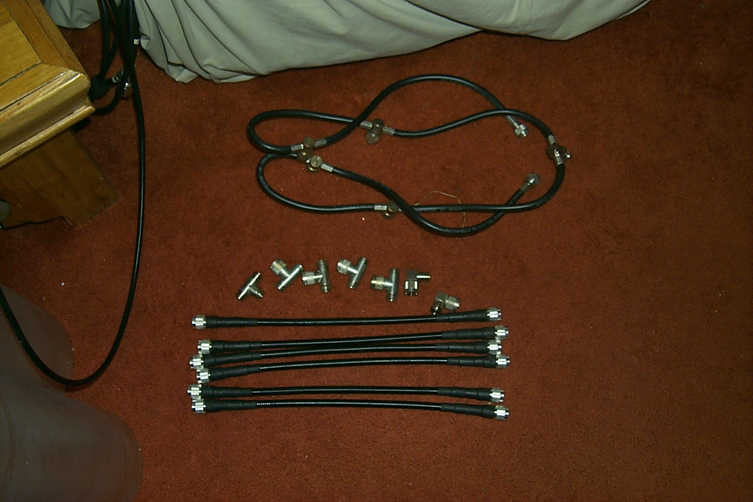
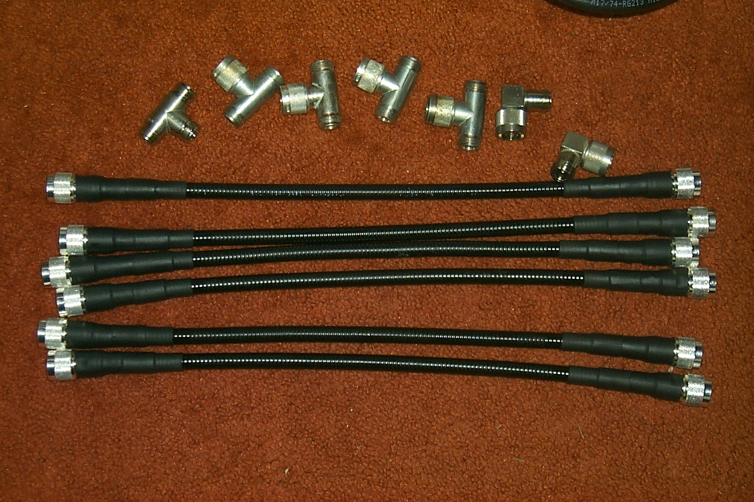
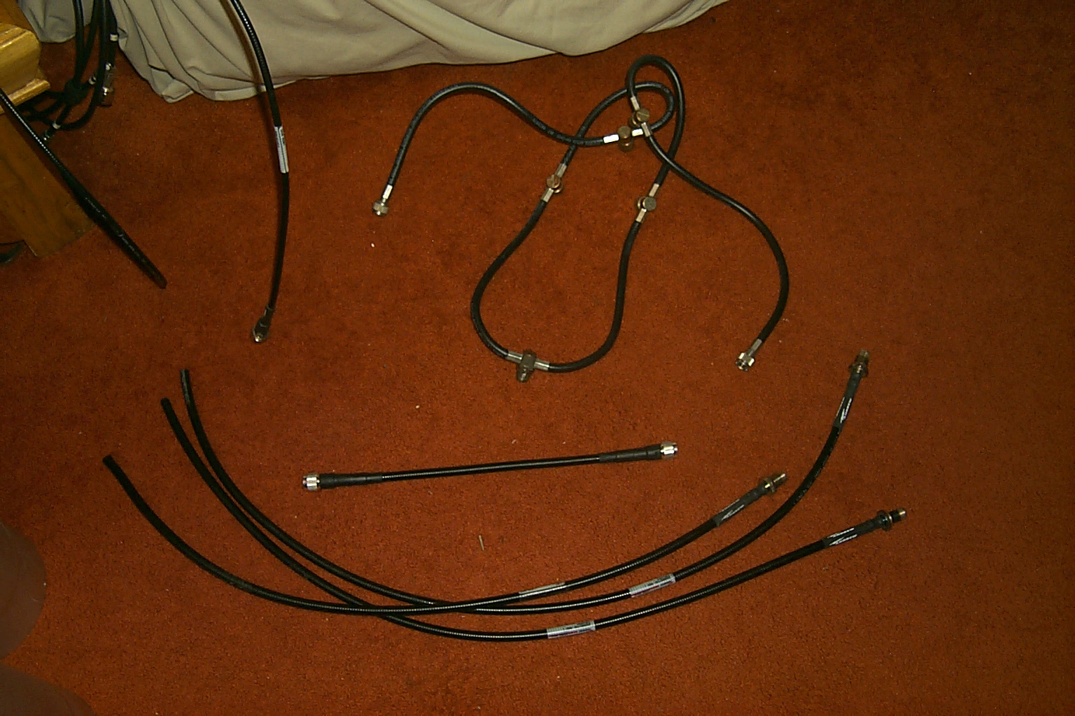
(click on images to enlarge)
Get it on the air!
Once I had the new cables made I installed them on the six cavities, tuned them up, and then placed the new upgraded duplexer loosely in the bottom cabinet to give them a try on the air.
(click on images to enlarge)
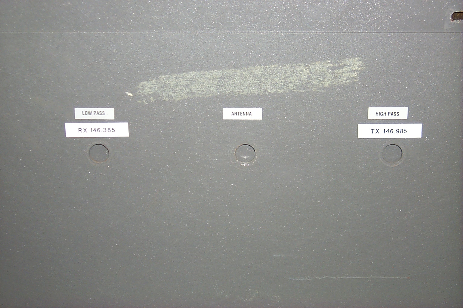
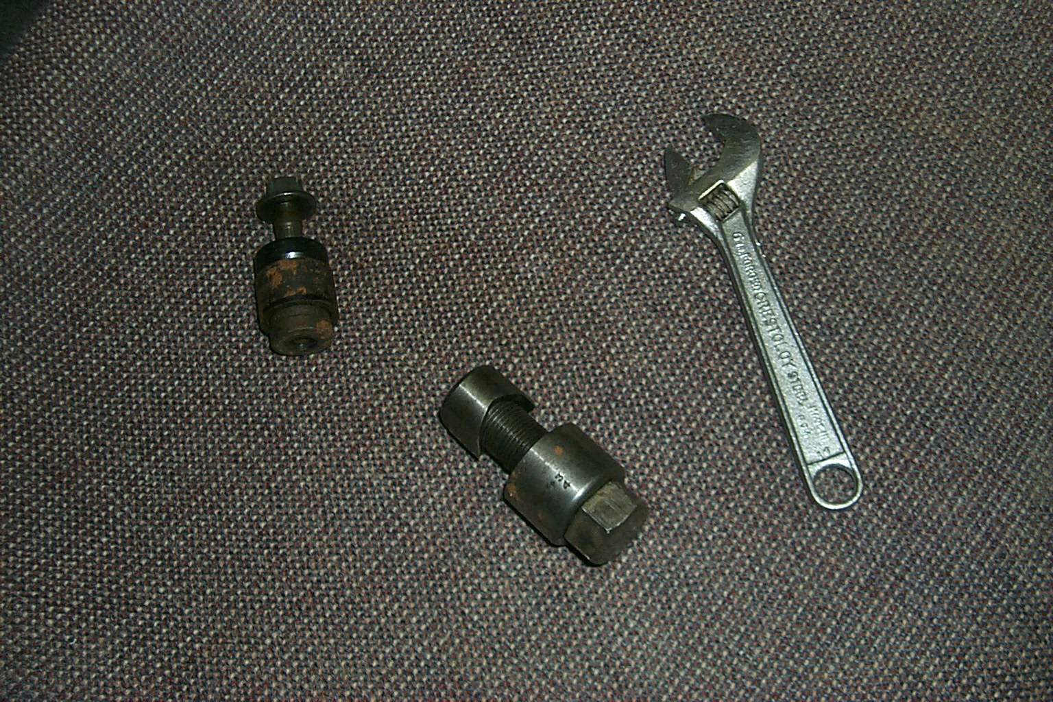
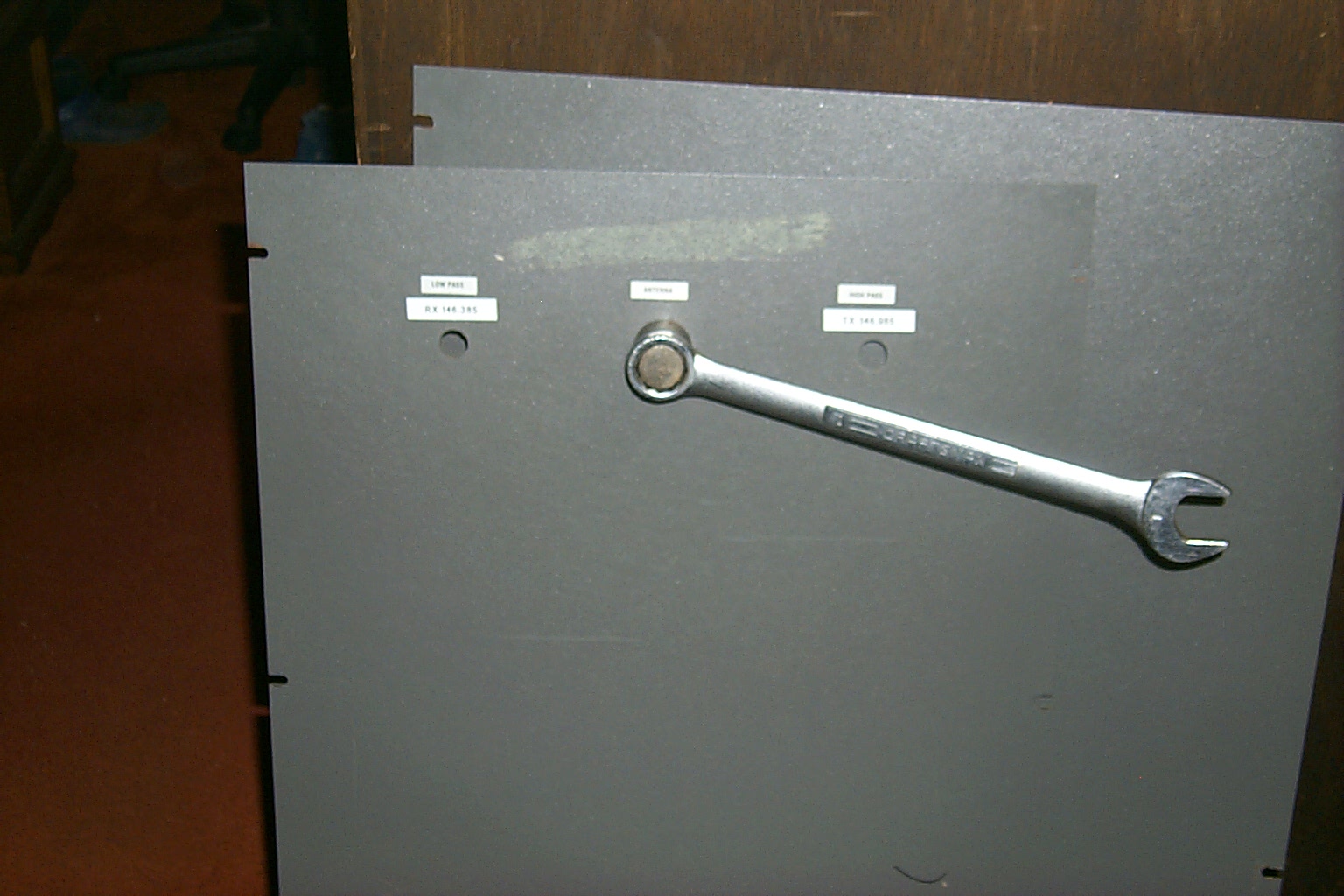
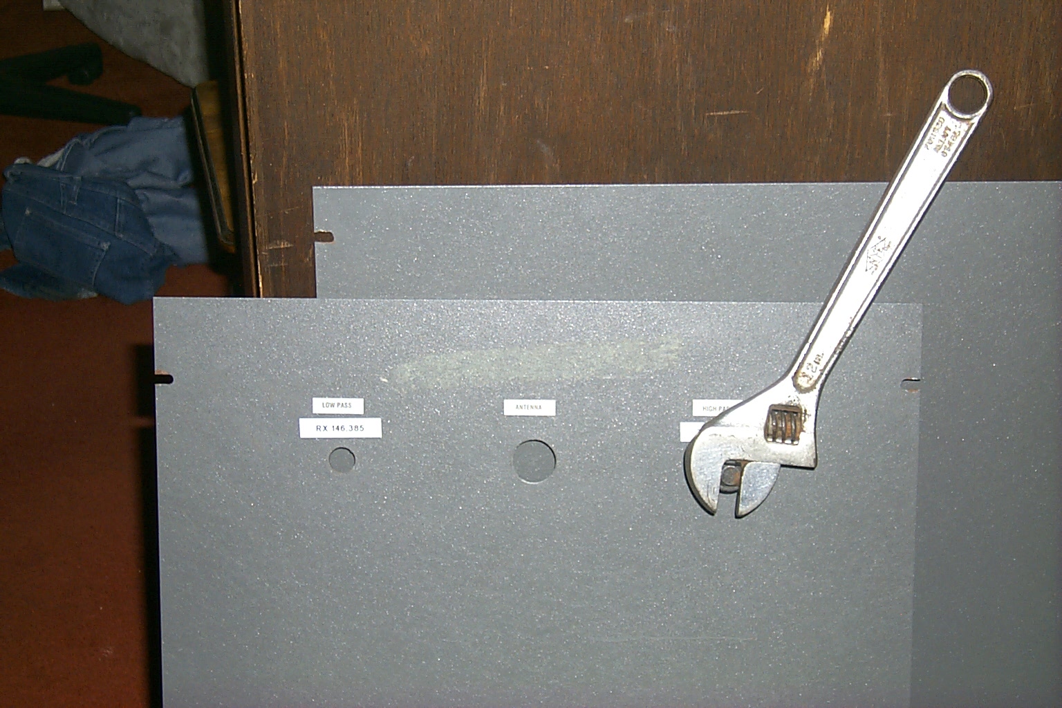
Where are those hole punches?
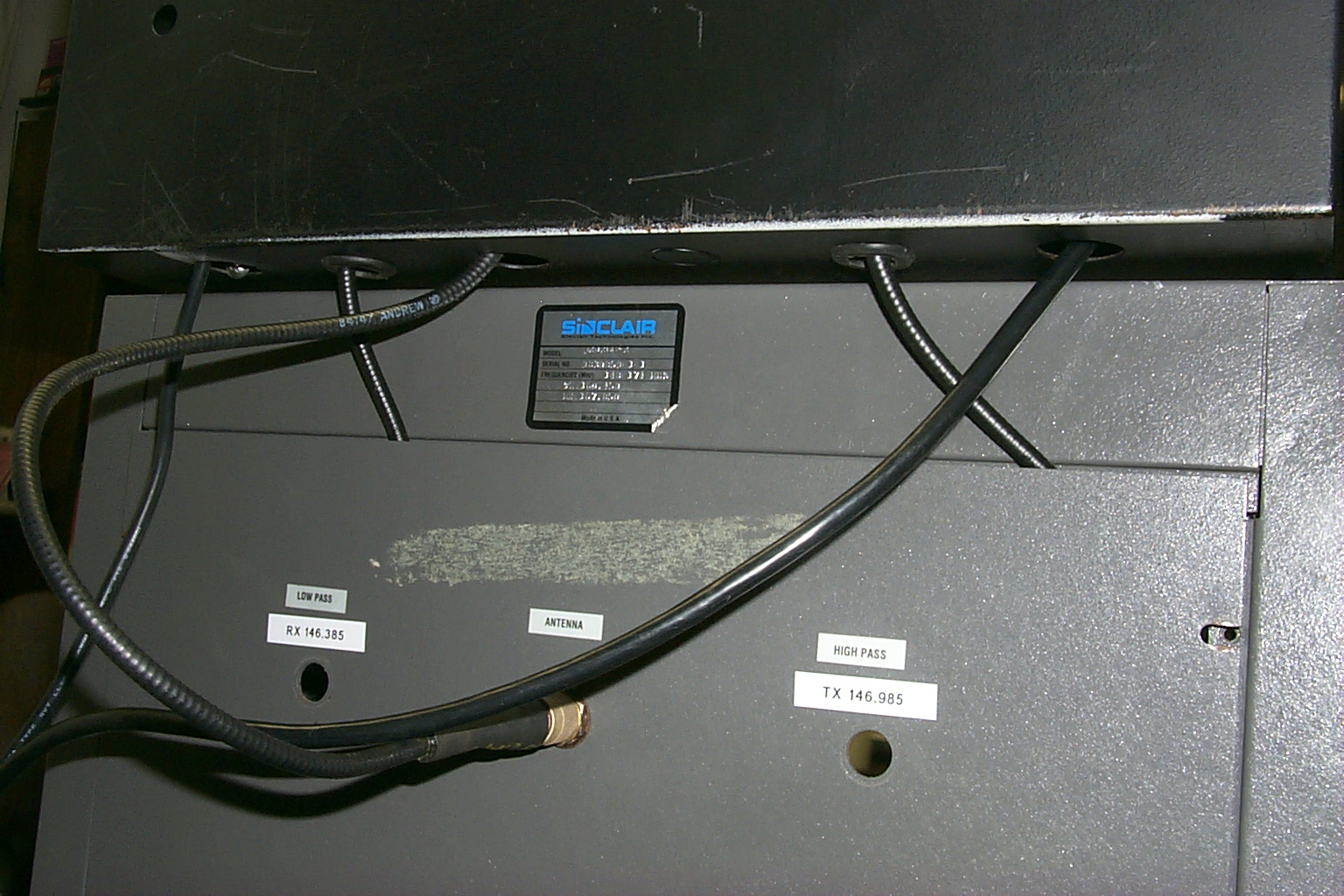
One of the other problems that I had was the original mounting holes for the crimped phasing harness were made to have the Type-N bulkhead connectors installed and I could not route the cables from the upper cabinet with the radios down into the lower cabinet with the duplexer. Because of this I had the old FSJ-1 cables going into the bottom cabinet thru the back cover which was pinching the cables.
In these photos you can see how I used a series of Greenlee punches to enlarge the hole so that I could route the new FSJ-2 cables into the bottom cabinet without damaging them between the cabinet and cover.
(click on images to enlarge)
Wait just a minute...
Ok I know what you are going to say when you see the next upgrade, I know that I just installed a new 50 Amp power supply little more than a week ago however it was a desktop model that was just sitting loosely in the bottom of the rack cabinet and it did not fit very well. So I pulled that out of the cabinet and installed a rack mounted 35 Amp supply.
The rack mounted power supply fit perfectly, it gave me a little more room in the upper rack cabinet too. That allowed me to drop the controller down about 2 inches and then lower the bottom shelf for the receiver and GLB Preselector/Peramp with all the toggle switches down as well. This straightened out the bottom shelf as well so Bruce KD1BE will hopefully stop complaining about that now.
(click on images to enlarge)
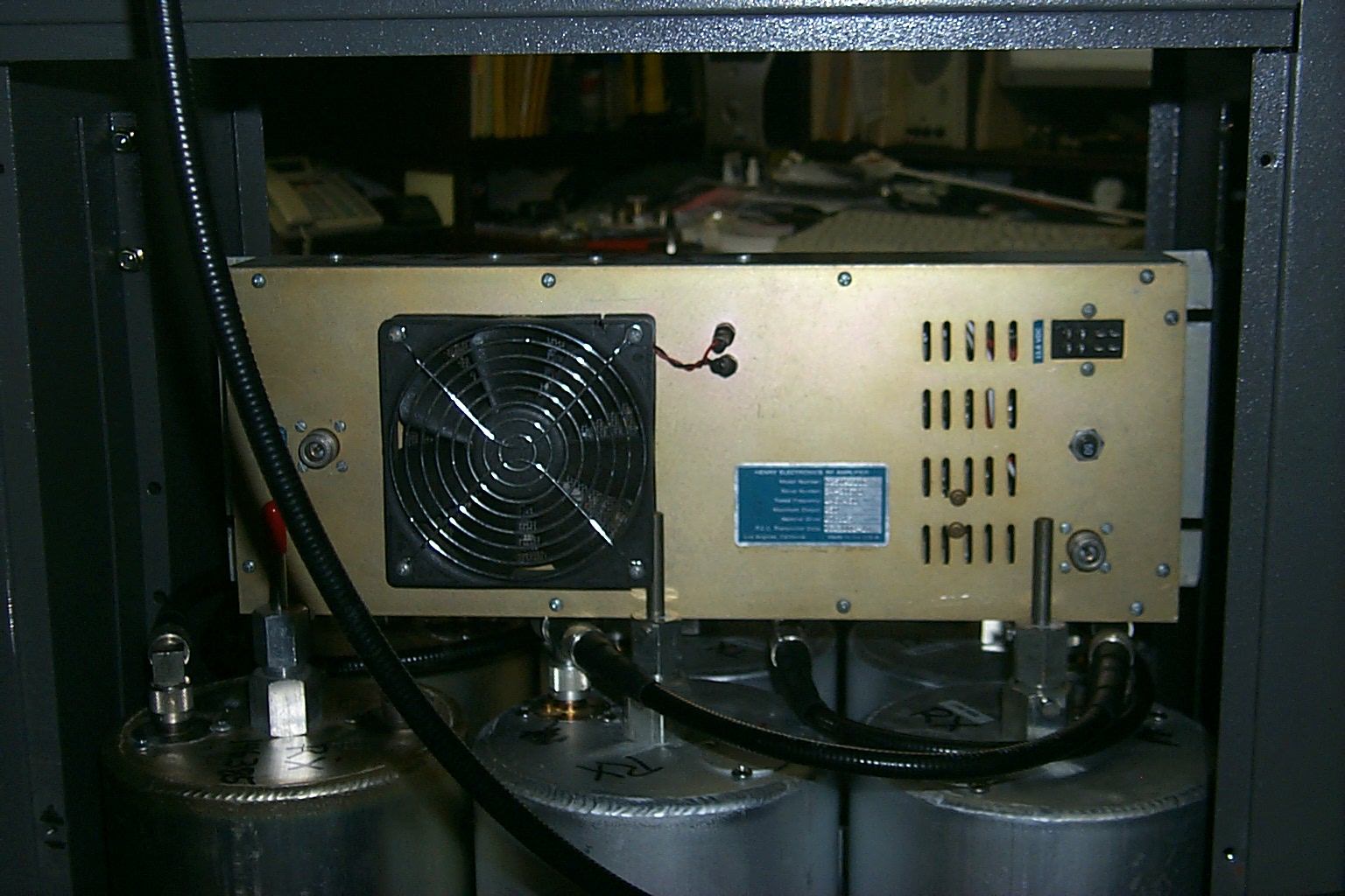
Finished with the duplexer mounts, all six cavities are securely in place with my staggered height adjustments for proper phasing cable placement, and I am fabricating the necessary mounts to bolt the power amplifier into the top of the bottom cabinet.
The PA has the standard 19" rack mounting setup but the inside of the duplexer cabinet is 22" across so I need to make some "dog ears" of extensions to mount the PA in that bottom cabinet. I have a blank rack plate here that I can have cut to the proper size that should work perfectly. I have the 250 watt PA resting on top of the duplexer so that I could make the measurements, when I have the brackets made I will mount the PA in the very top of the cabinet which should place it about 6 inches above the duplexer. Maybe Sandy's brother or Bruce and Jon can help me get the PA mounting brackets cut to size, I could even go at the plate with a hacksaw if I get desperate!
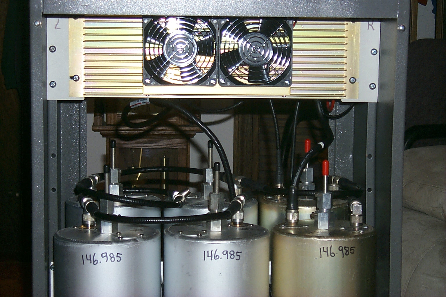
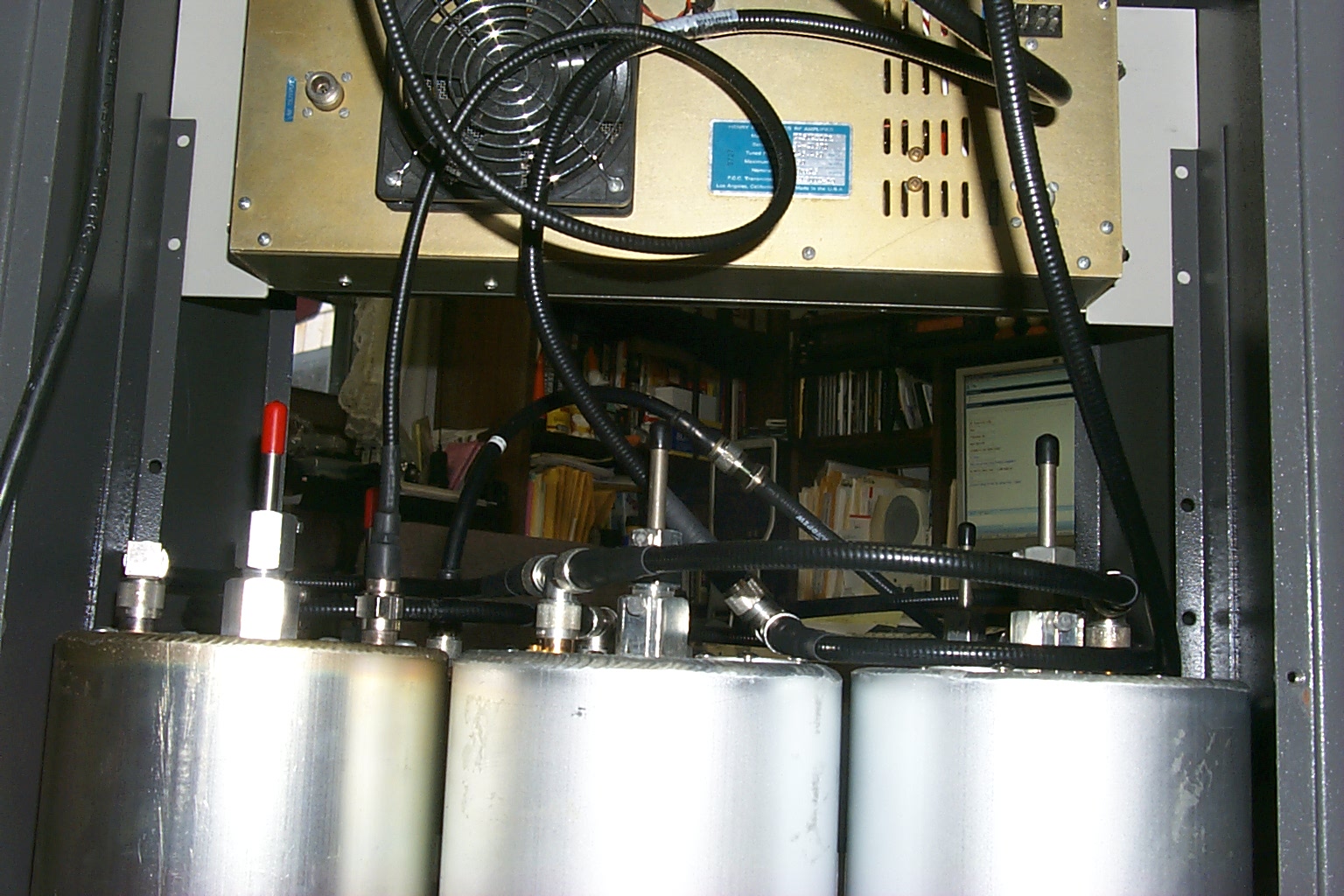
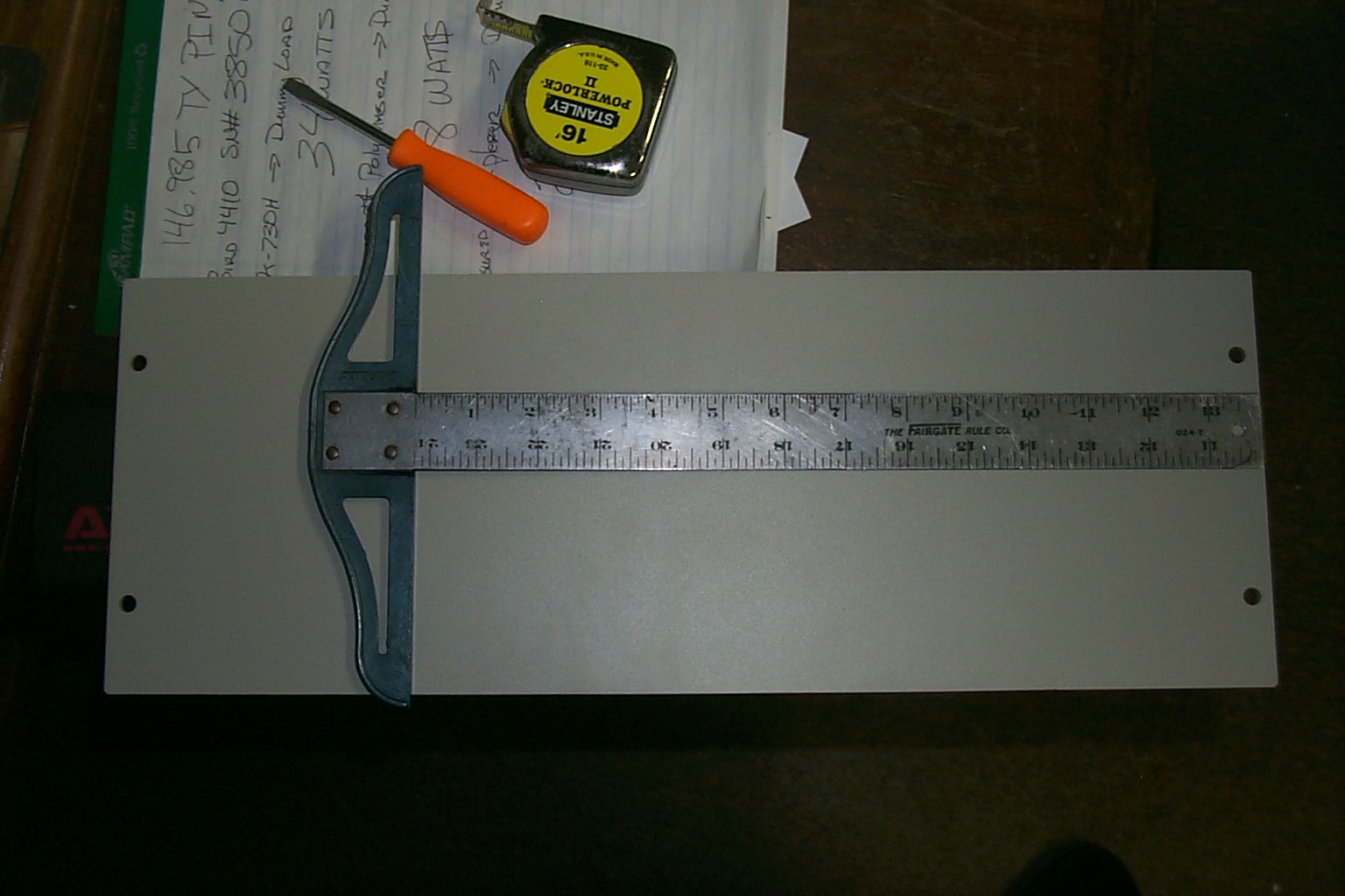
(click on images to enlarge)
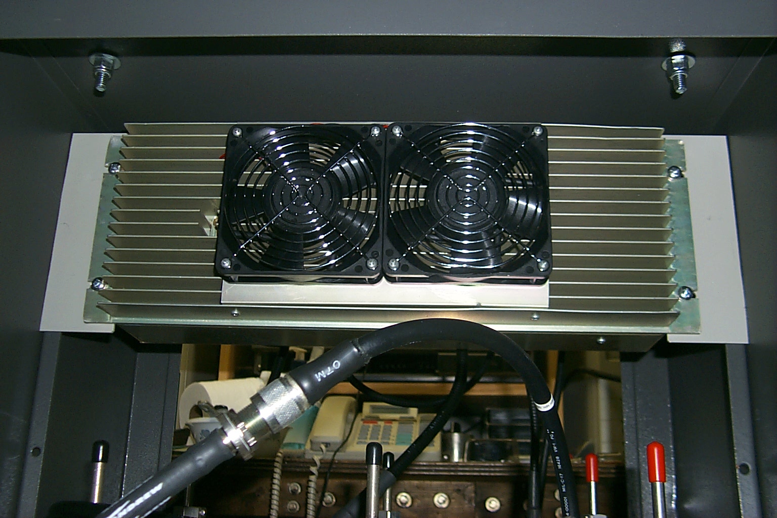
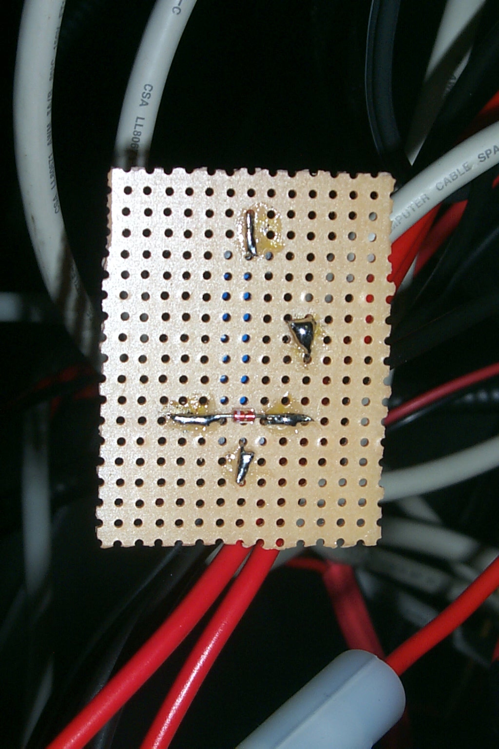
Then late last night I read some more in that funny book with all the instructions and was able to create a series of programming macros in the 7K controller that will turn all the fans on and off with transmitter activity. I just have to build a circuit to connect the controller logic to a relay that will cycle the fans. I should be able to get that finished today after I complete mounting the duplexer cavities etc.
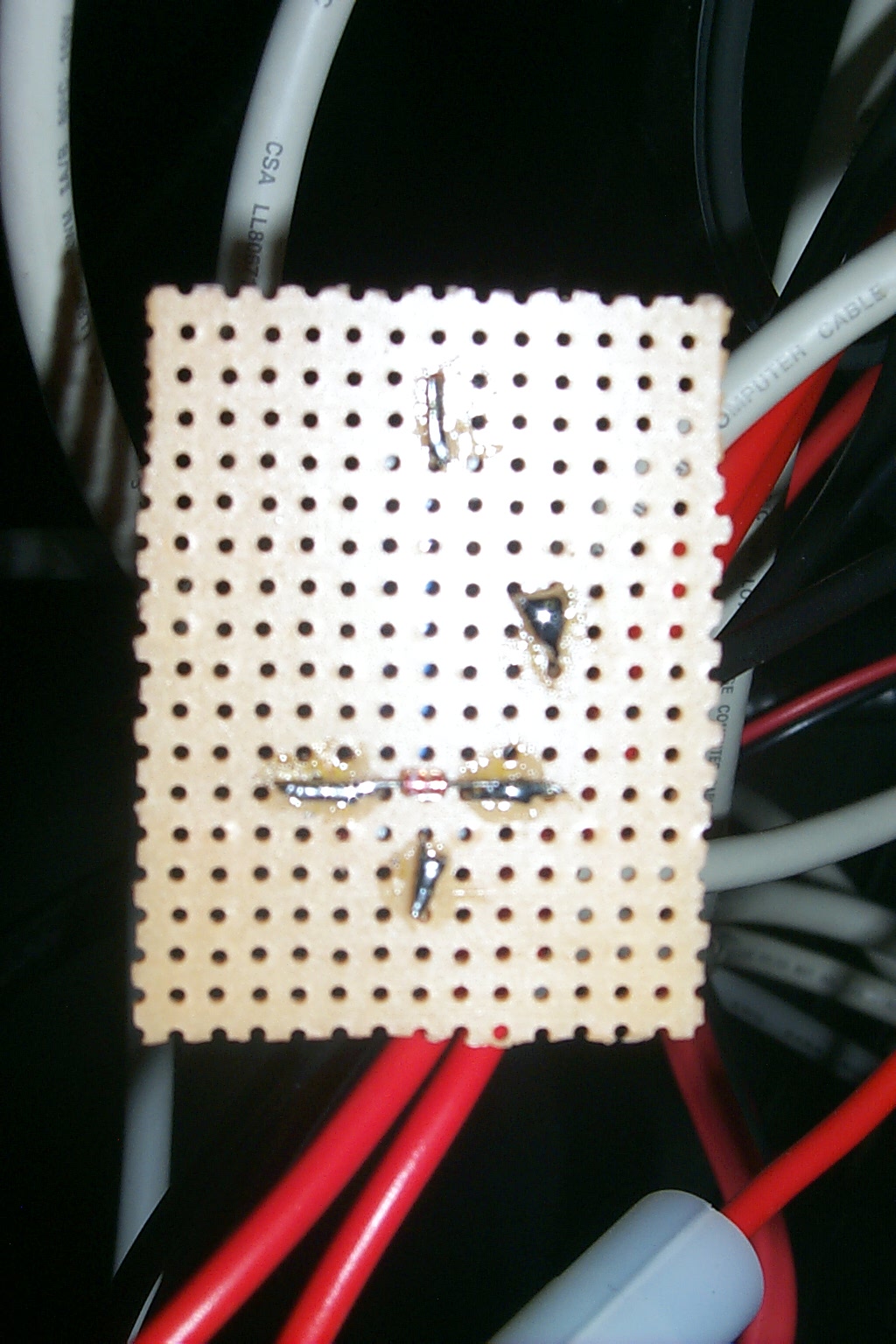
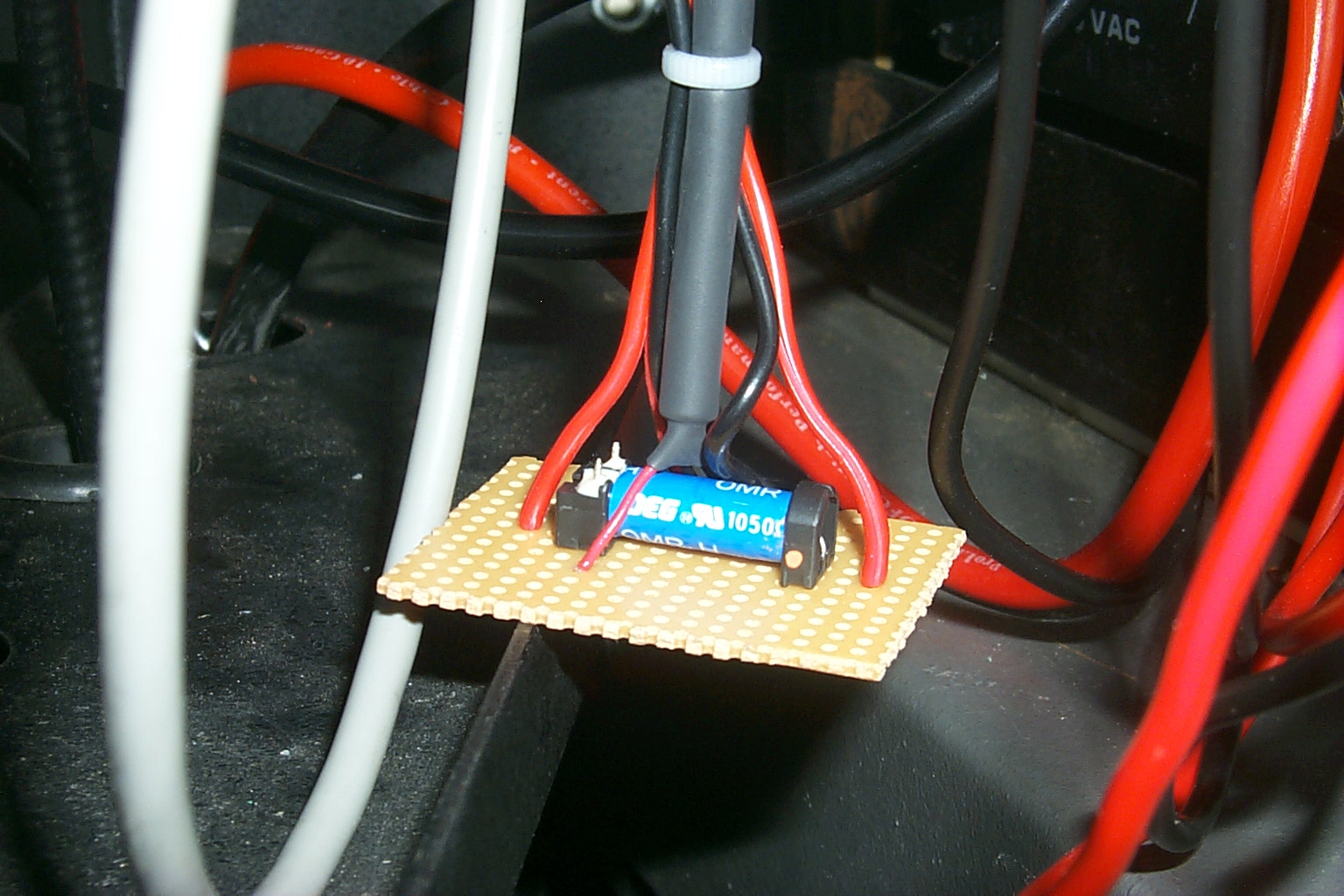
(click on images to enlarge)
Update January 2010 - Rebuild / Upgrade
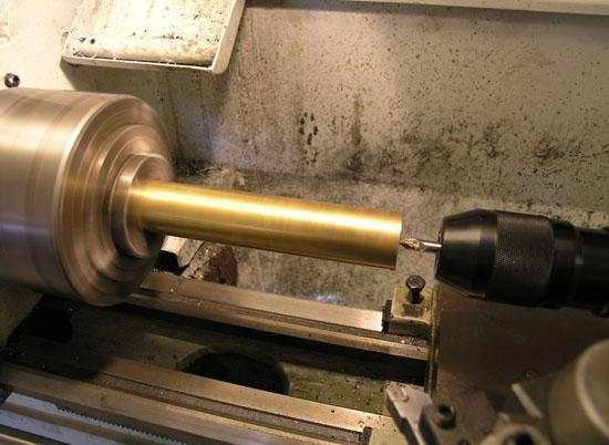
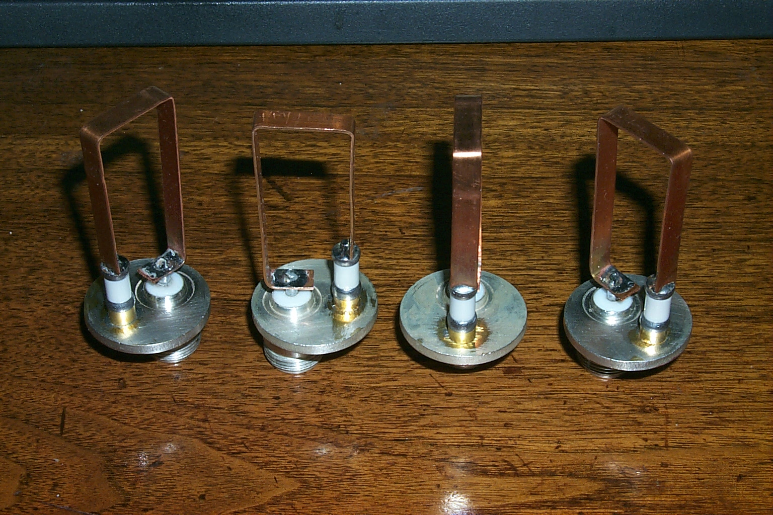
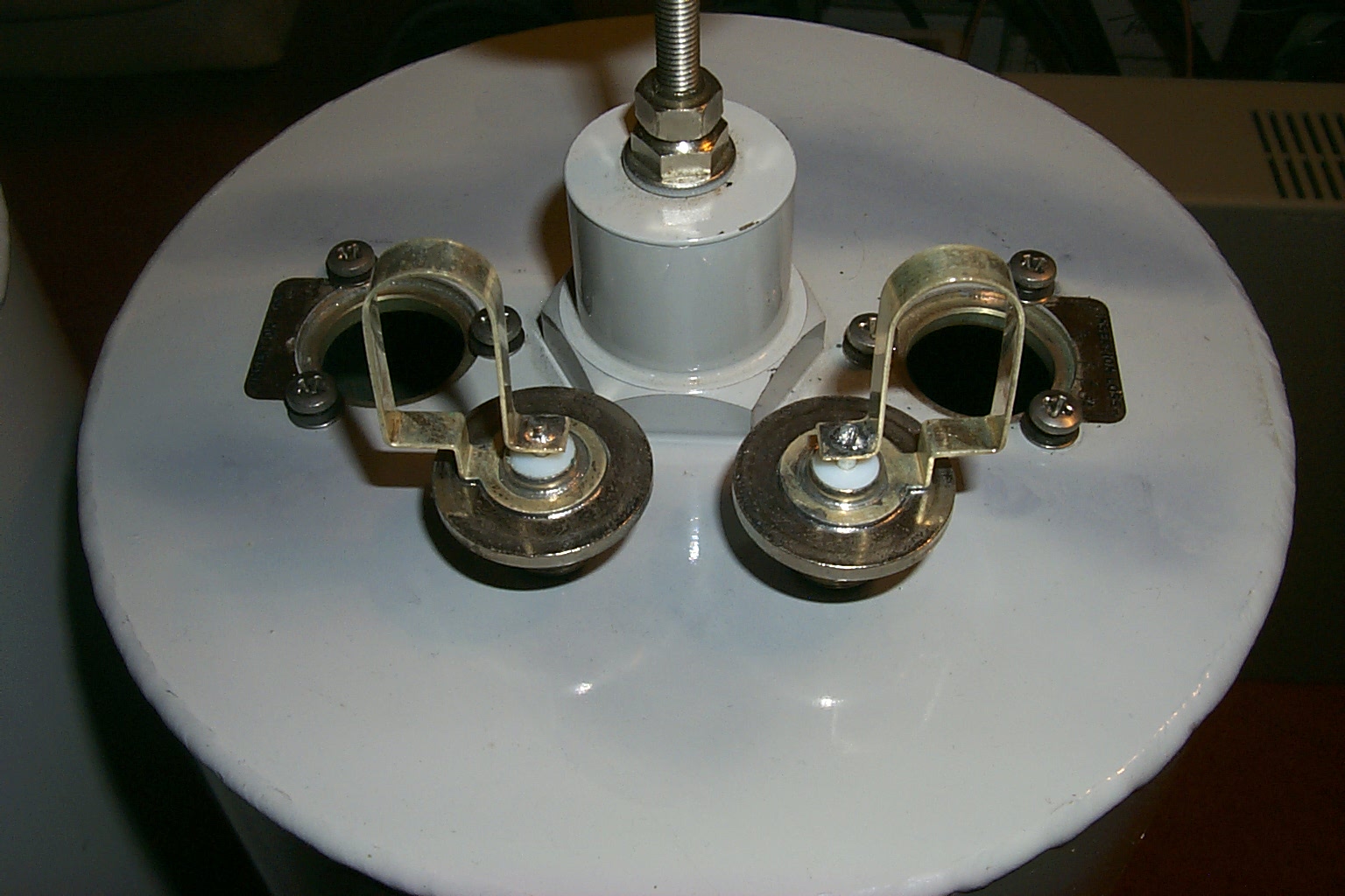
The final configuration or "Version 3.01 Nine Eight Five" has finally kicked off. I have started the work to convert the original K1DA 8" Wacom duplexer cavities that have SO-239 coupling loops with external reject notch tubes with new custom Type-N loops with piston caps for the reject notch. I am also replacing the braded coax jumpers with custom FSJ4-50 Heliax cables and silver plated Type-N connectors all cut to the exact 1.4 wave, 1/2 wave, and full wave lengths for 146.985 & 146.385 MHz.
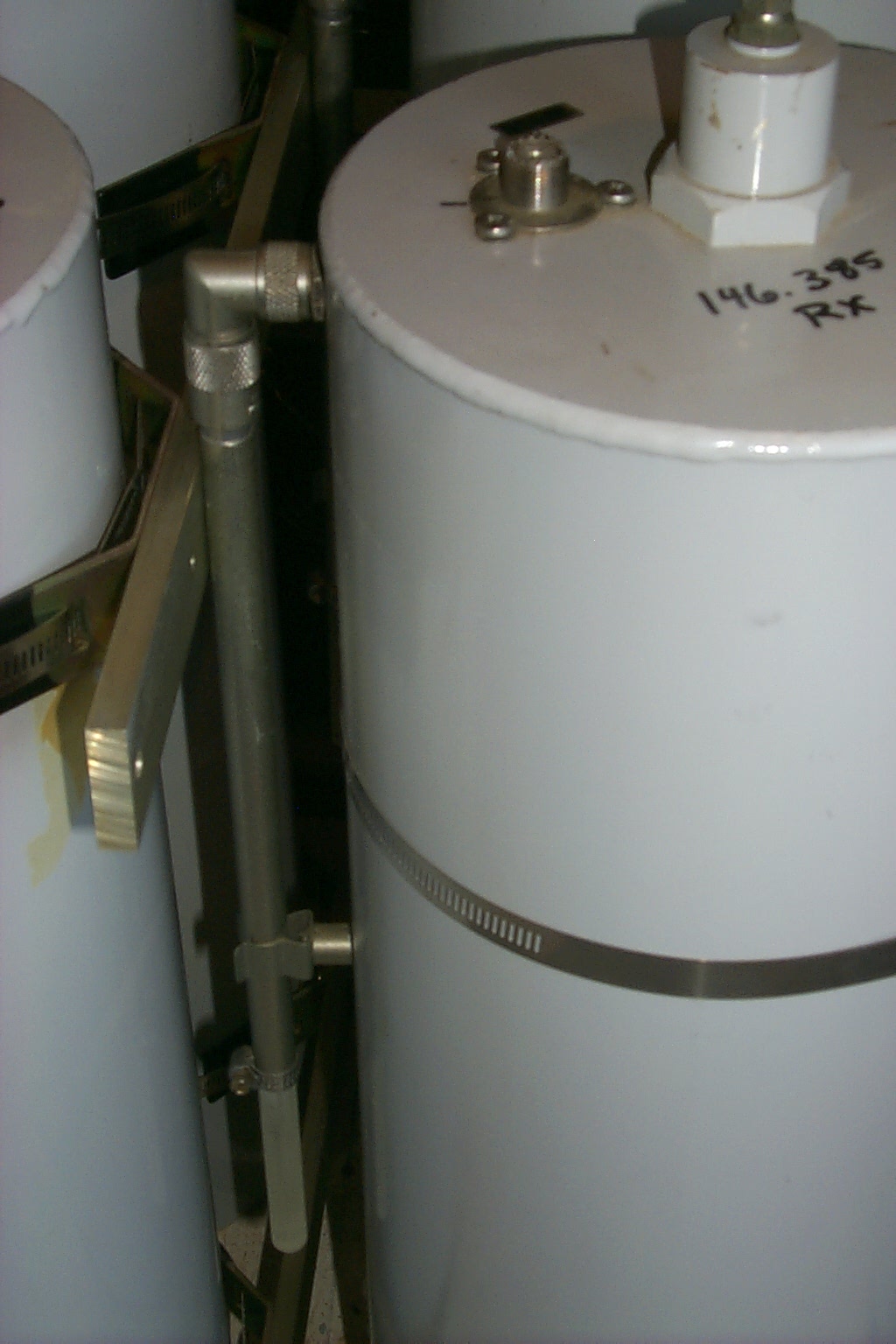
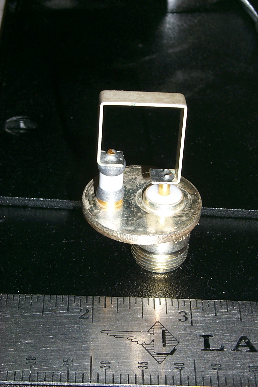
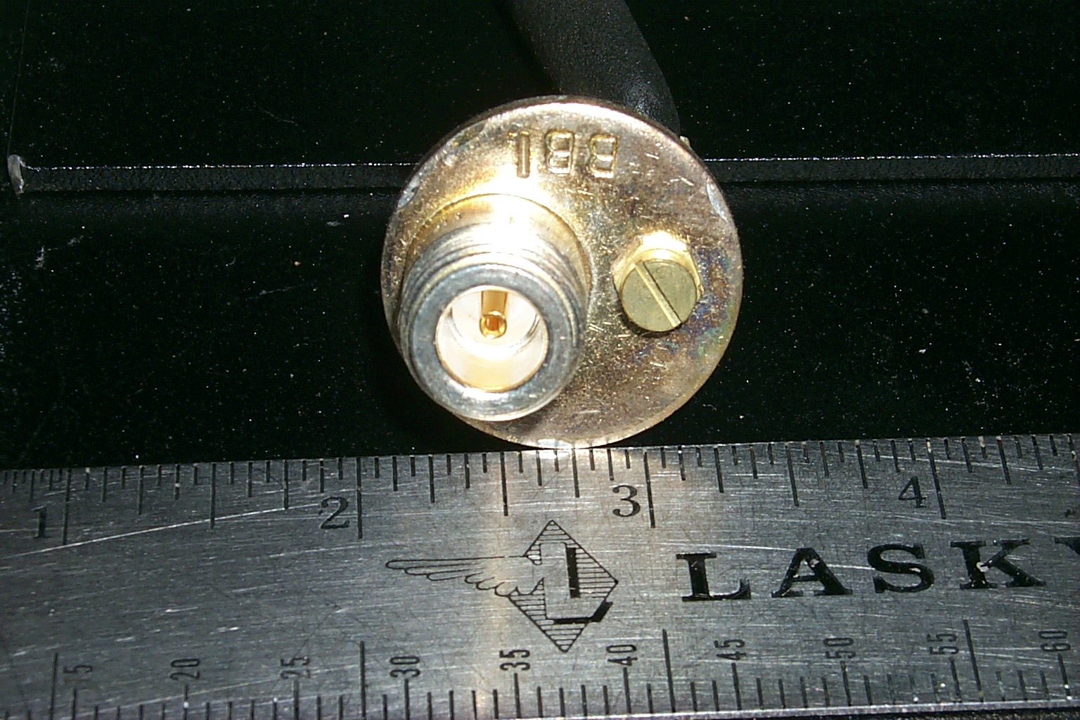
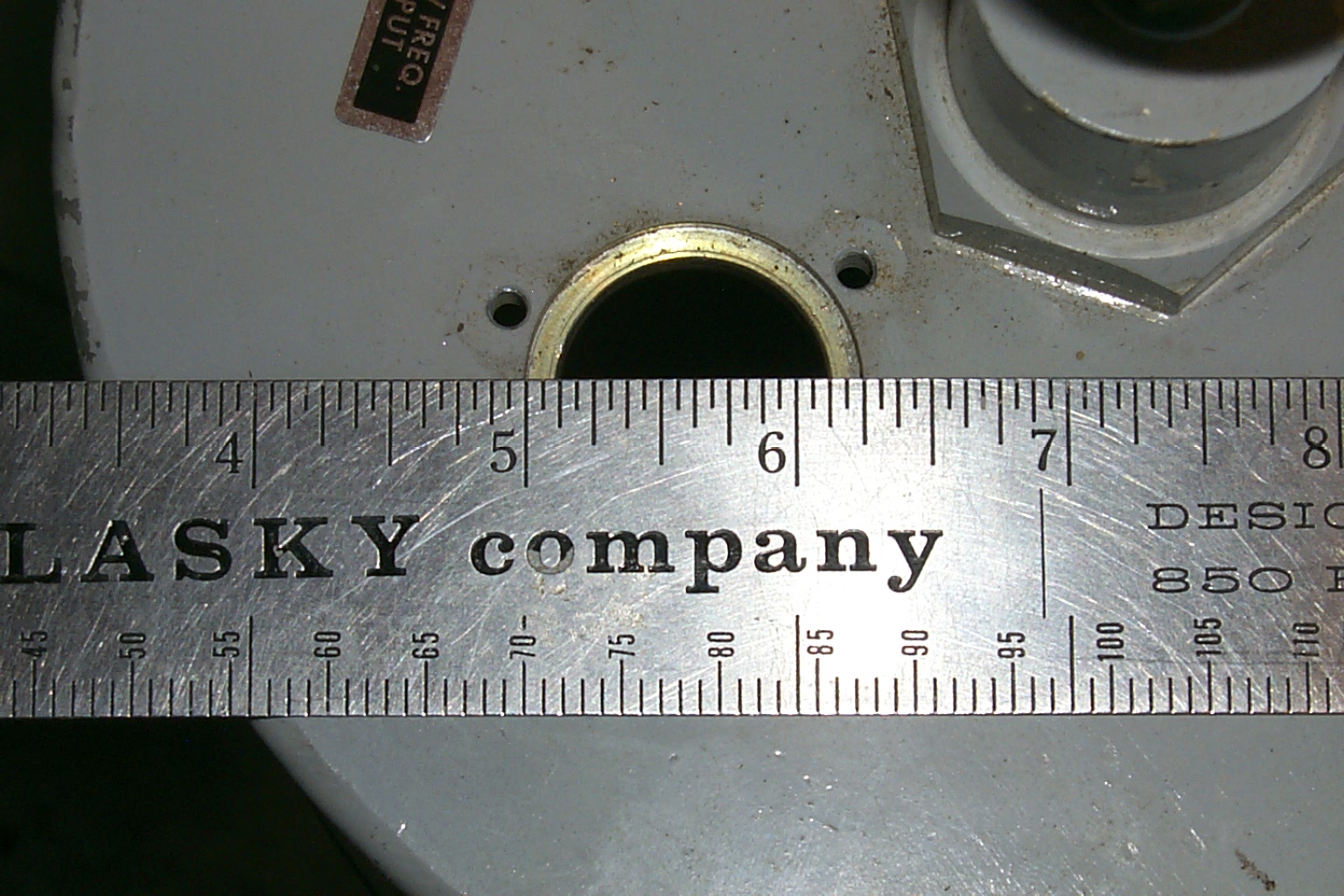
(click on images to enlarge)
Roland N1JOY supplied the Andrew FSJ4-50 Superflex Heliax and silver plated Type-N connector. He also help fabricate the jumpers all cut to the exact 1/4 wave, 1/2 wave, and full wave lengths with his precision equipment in the HAMCOW.
HAMCOW - http://www.qsl.net/hamcow/ (HAM Radio Communications On Wheels)
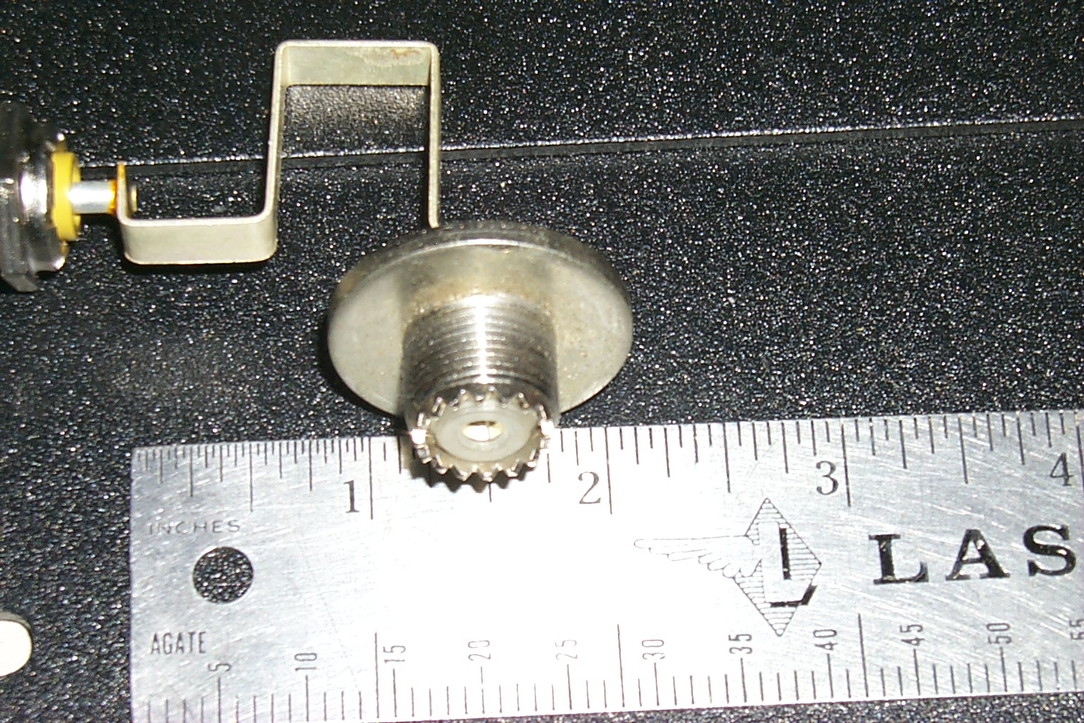
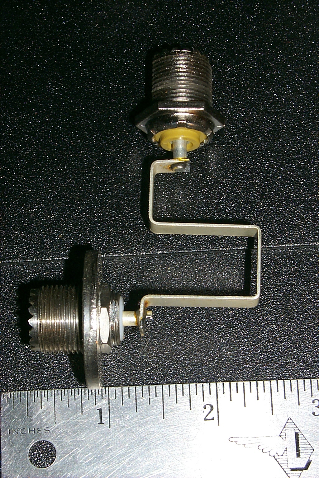
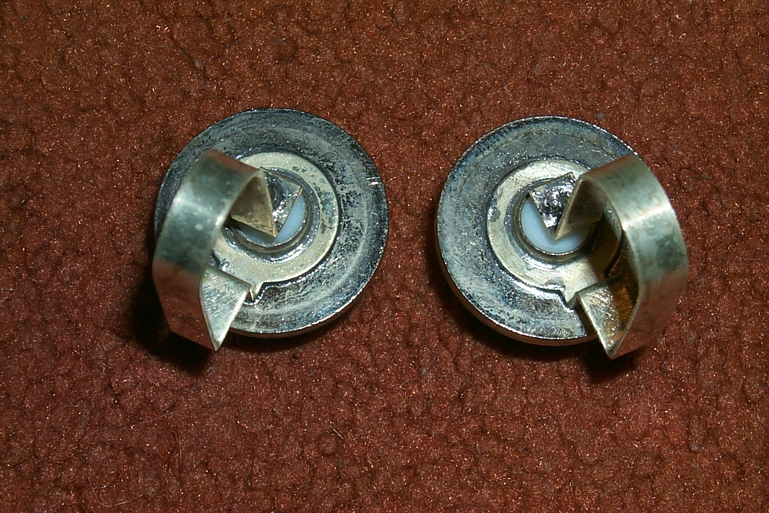
New custom "JAG" coupling loops
(click on images to enlarge)
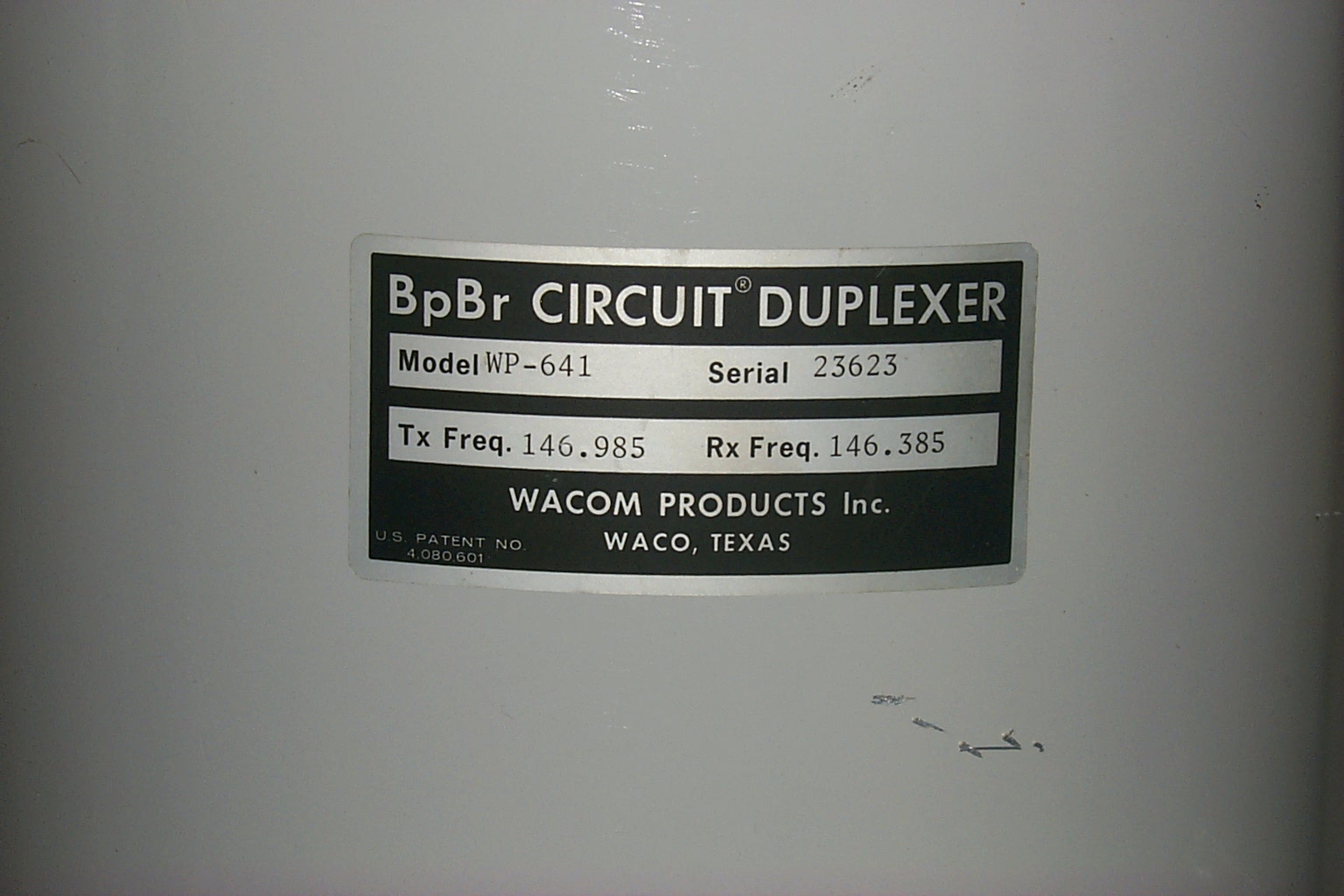
They were able to make new custom loops to my exact specifications for the Wacom WP-641 cavities and because they knew the exact TX & RX frequencies I would be tuning the cavities for they were able to optimize the loops on my repeater pair.
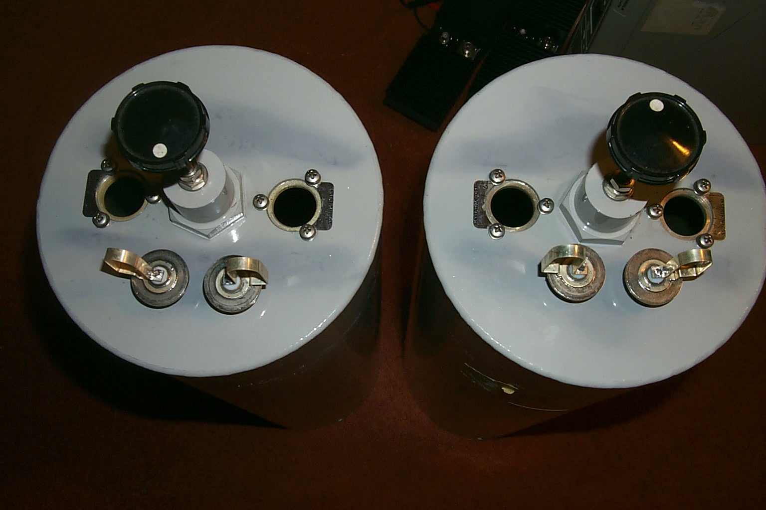
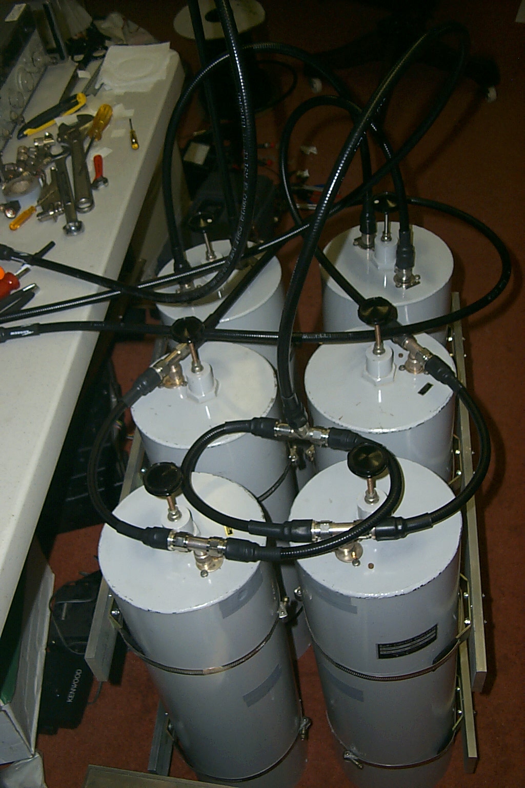
Putting is all together...
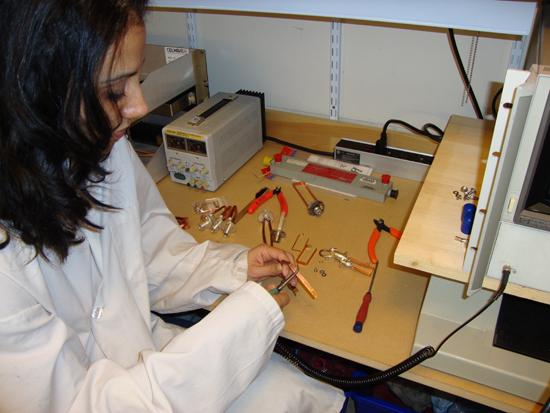
With all the new JAG coupling loops in hand I started making the new phasing cables using Andrew FSJ4-50B super-flex and Type-N connectors.


(click on images to enlarge)
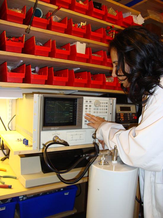
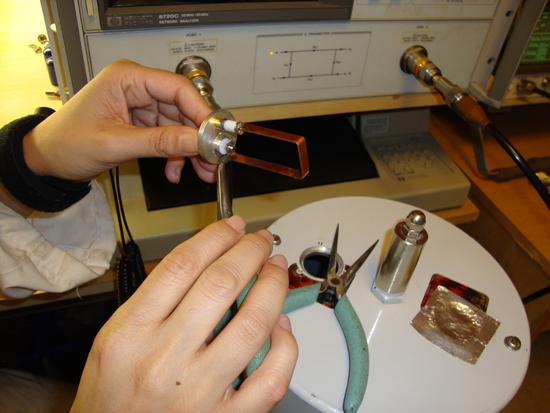
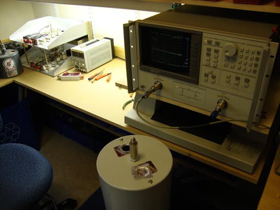
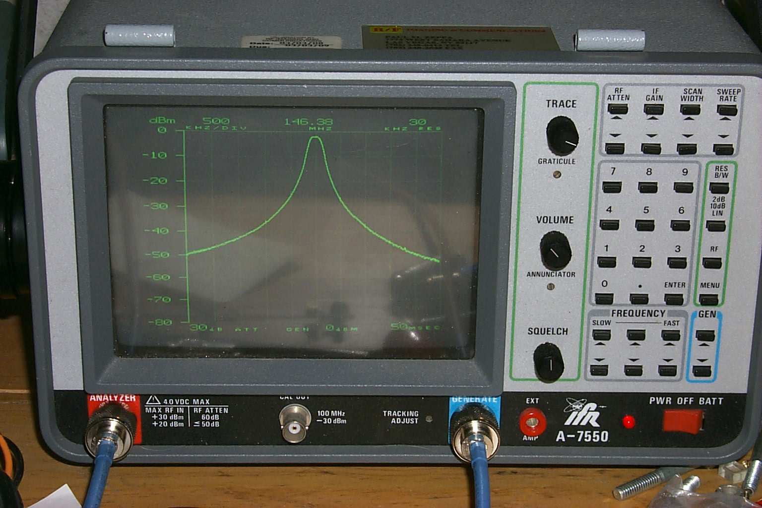
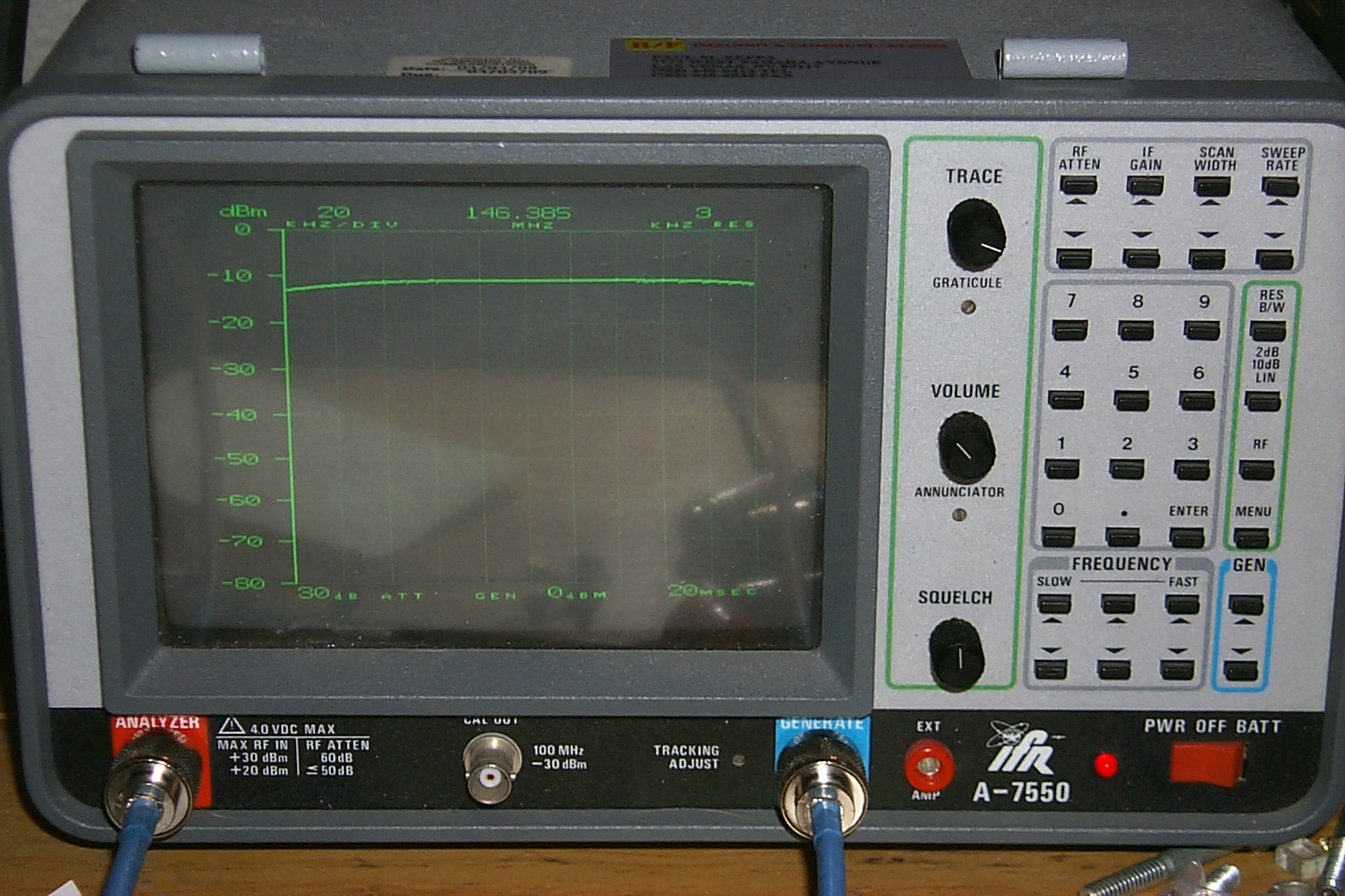
New jumpers and initial tune-up...
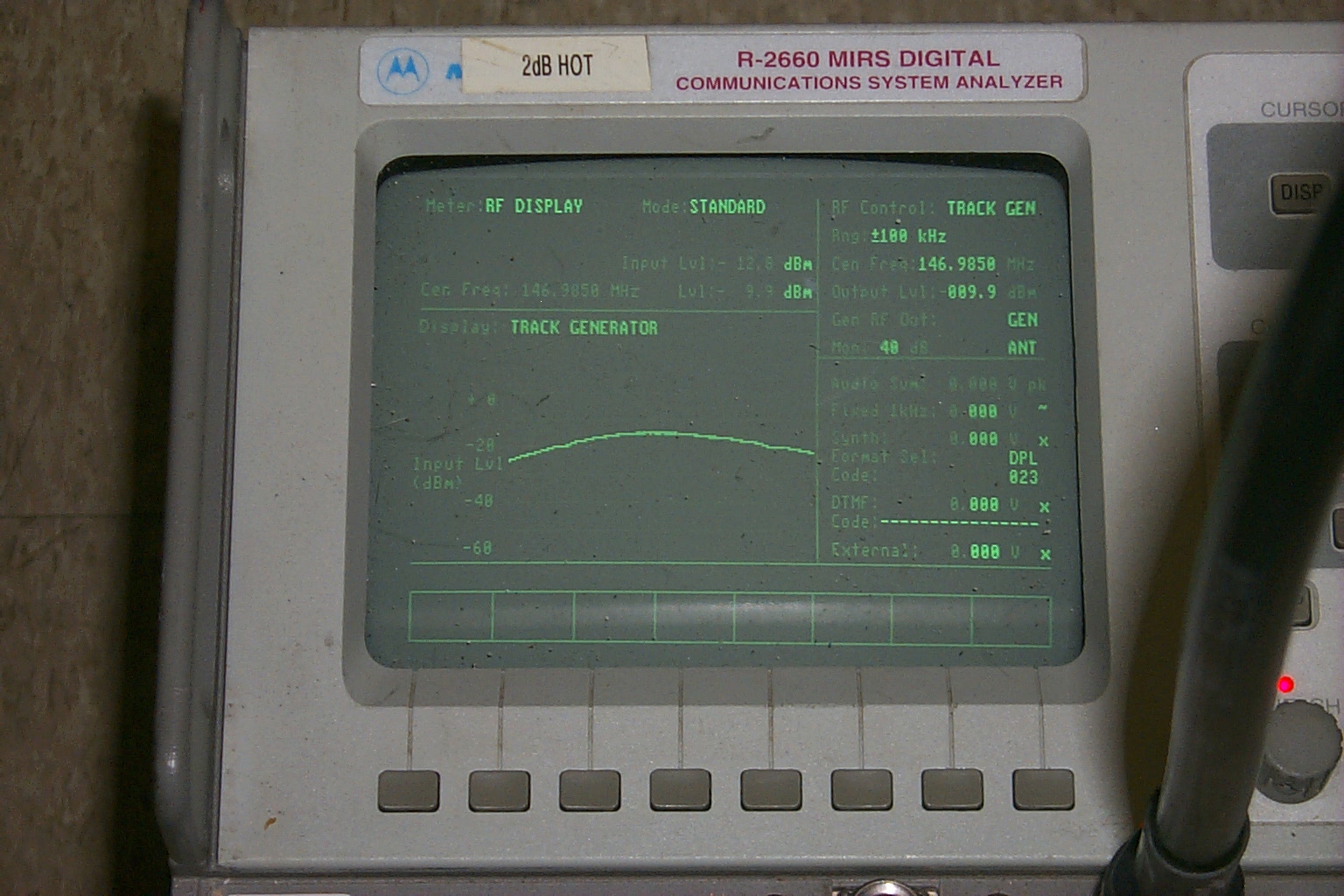
Once I had all the new jumpers ready I connected the phasing harness and did a ruff tune-up using my return loss bridge and IFR before loading up the cavities and brining them over to the HAMCOW for the final tuning.

(click on images to enlarge)
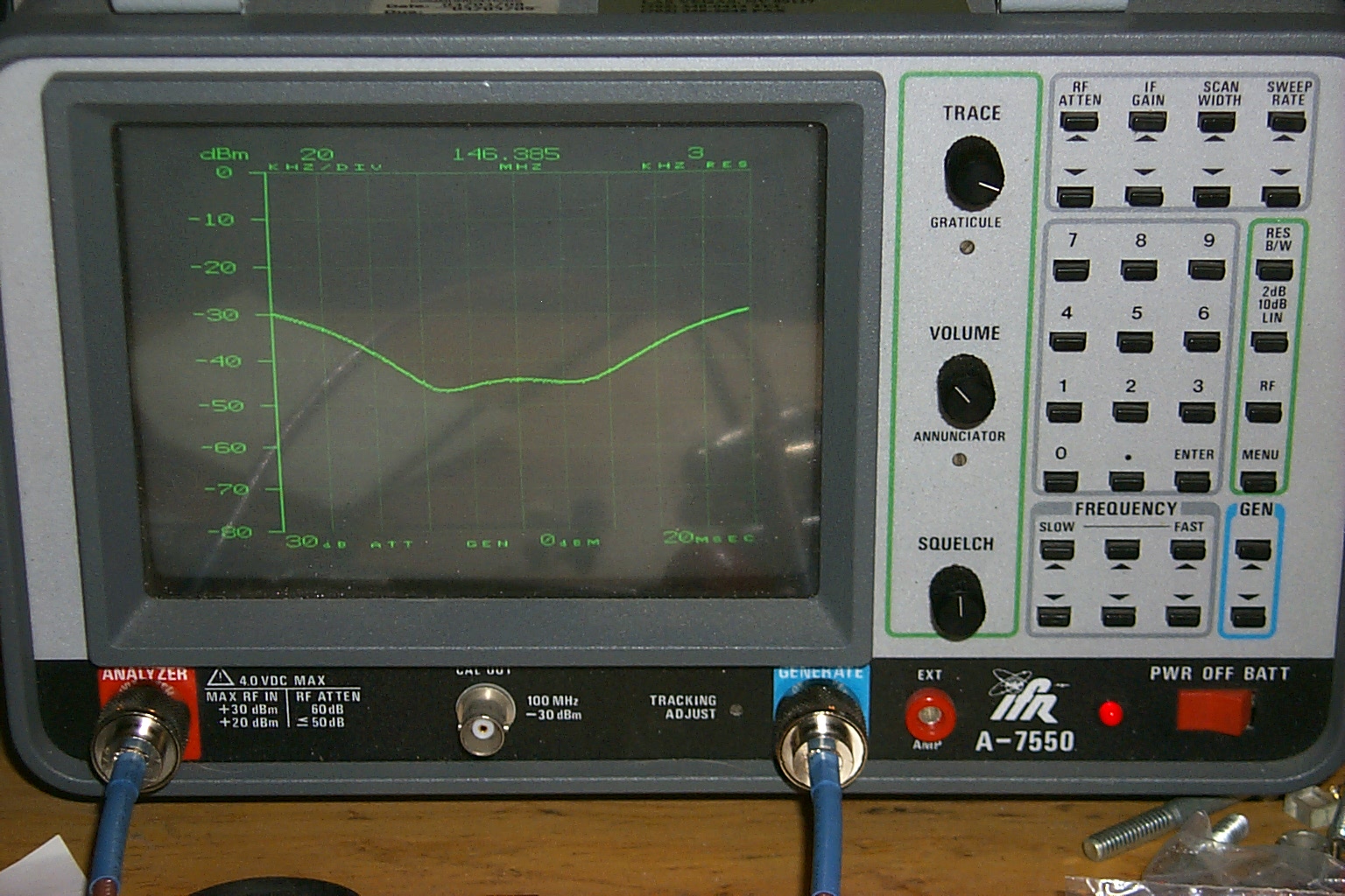
(click on images to enlarge)
Another super duper tune-up session in the HAMCOW with Roland!
(click on images to enlarge)
Much more fun on the way, look for updates soon!
Return to the KA1RCI Repeater Network Home Page
This page was last updated on 09/26/2010
Send mail to [email protected] with questions or comments about this web site.
Copyright 1995-2010 Steven M Hodell
Copyright in these pages, in the screens displaying the pages and in the information, materials and other content contained in this web site is owned by Steven M Hodell unless other wise indicated and is protected by U.S. and international copyright laws and treaties. The information, materials and other content of this web site may not be copied, displayed, distributed, downloaded, licensed, modified, published, reposted, reproduced, reused, sold, transmitted, used to create a derivative work, or otherwise used for public or commercial purposes without express written consent.