Established 1984
North 80 Foot Repeater Tower
Preview of the New Antennas - 2010
Coming Soon...The New Antennas!
I will be replacing the 20+ year old Diamond antennas with two new Hustler's. A G7-144 for the 146.460 repeater and a G7-220 for the 224.040 repeater. I have several of the G7-144 antennas deployed around the state on my other repeaters and I have been very impressed with the performance.
I am also going to install an array of commercial set of DB-408 UHF exposed dipoles on the main mast for the 447.775 repeater while we are doing all this work. I have been running both the 146.460 and 447.775 repeaters on the Diamond X500-NHA but that will no longer be possible with the new G7-144 so the dipoles seemed like a good choice.
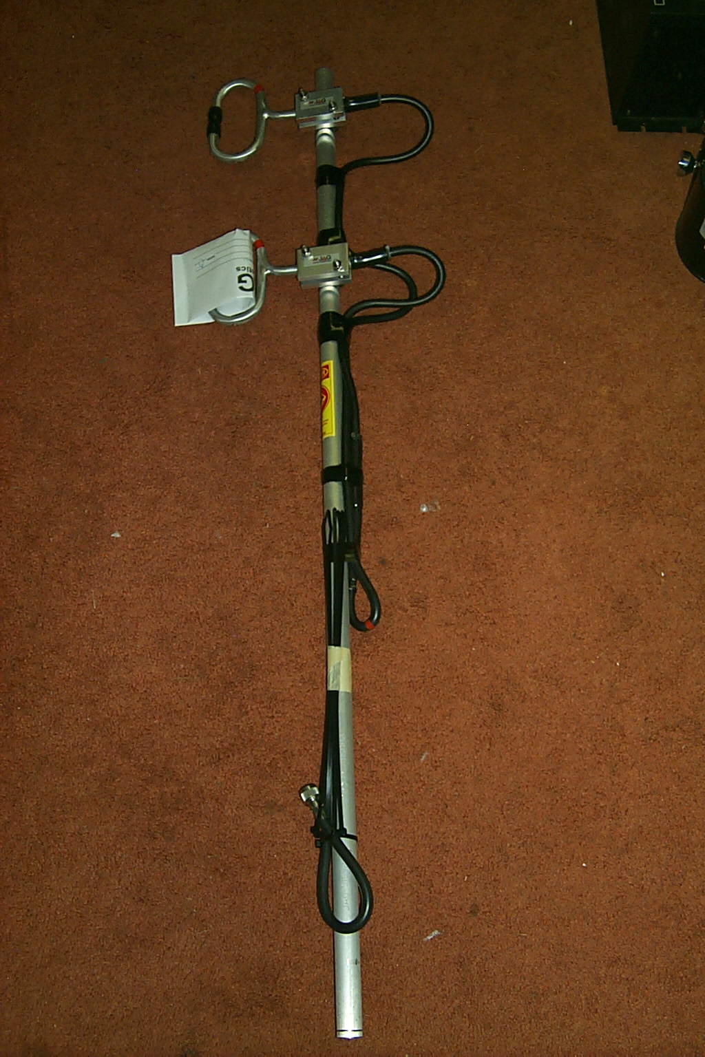
The last new addition will be the new custom JAG Electromagnetics 900 MHz exposed dipole array for the Lincoln 927.6125 repeater. I have been running this repeater on a small 5/8th wave magnetic mount antenna stuck to the top of the rack cabinet in the repeater vault. It has basically been an intercom for us to use at the house...

(click on images to enlarge)
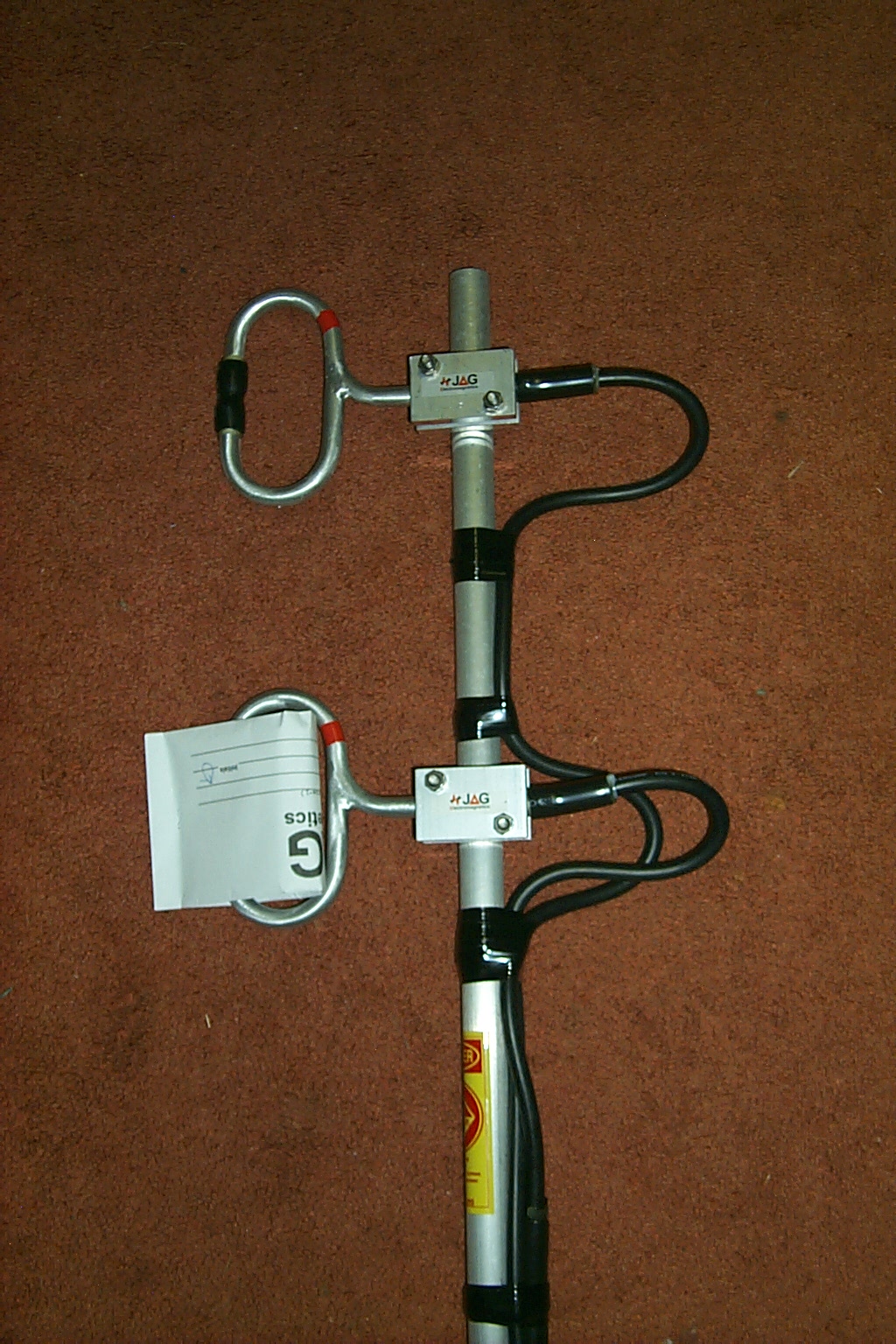
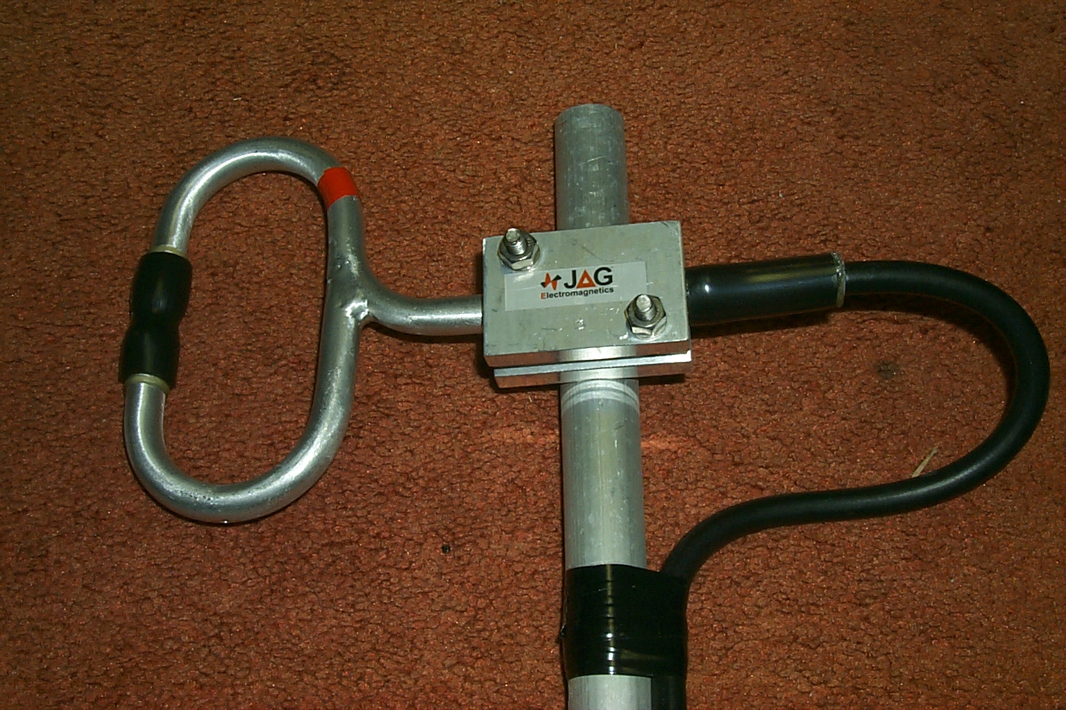
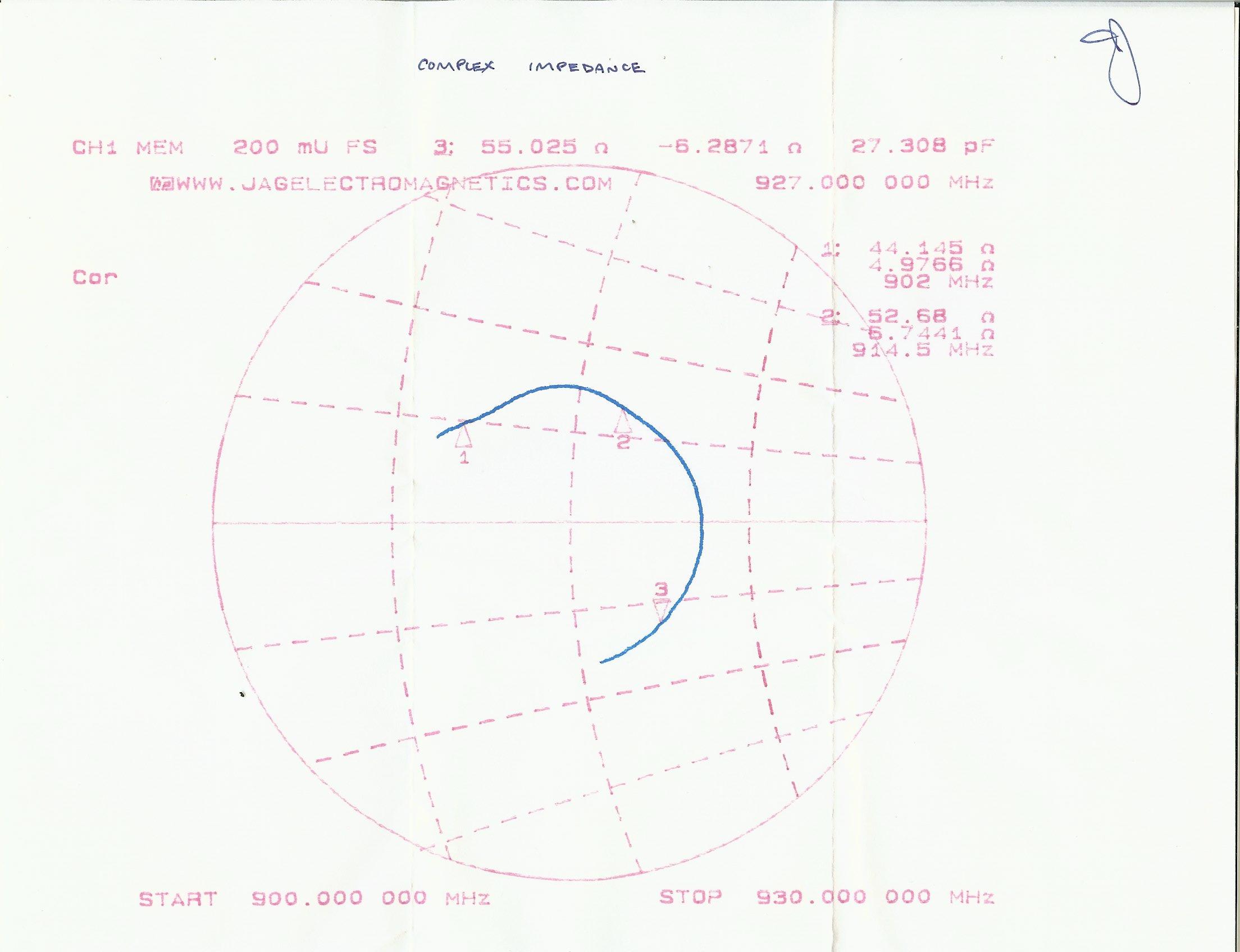
I asked Jag to build me a repeater antenna for my Lincoln 927.6125 repeater and boy did he ever, the more that I look at the papers Jag sent me with this antenna the more I am blown away. He custom designed and built this one per my request, I asked for a high performance repeater antenna that would work in the Amateur band split 927 / 902 MHz and be small and light for my little tower.
If I am reading these charts correctly (images below) he really knocked this
one out of the park.
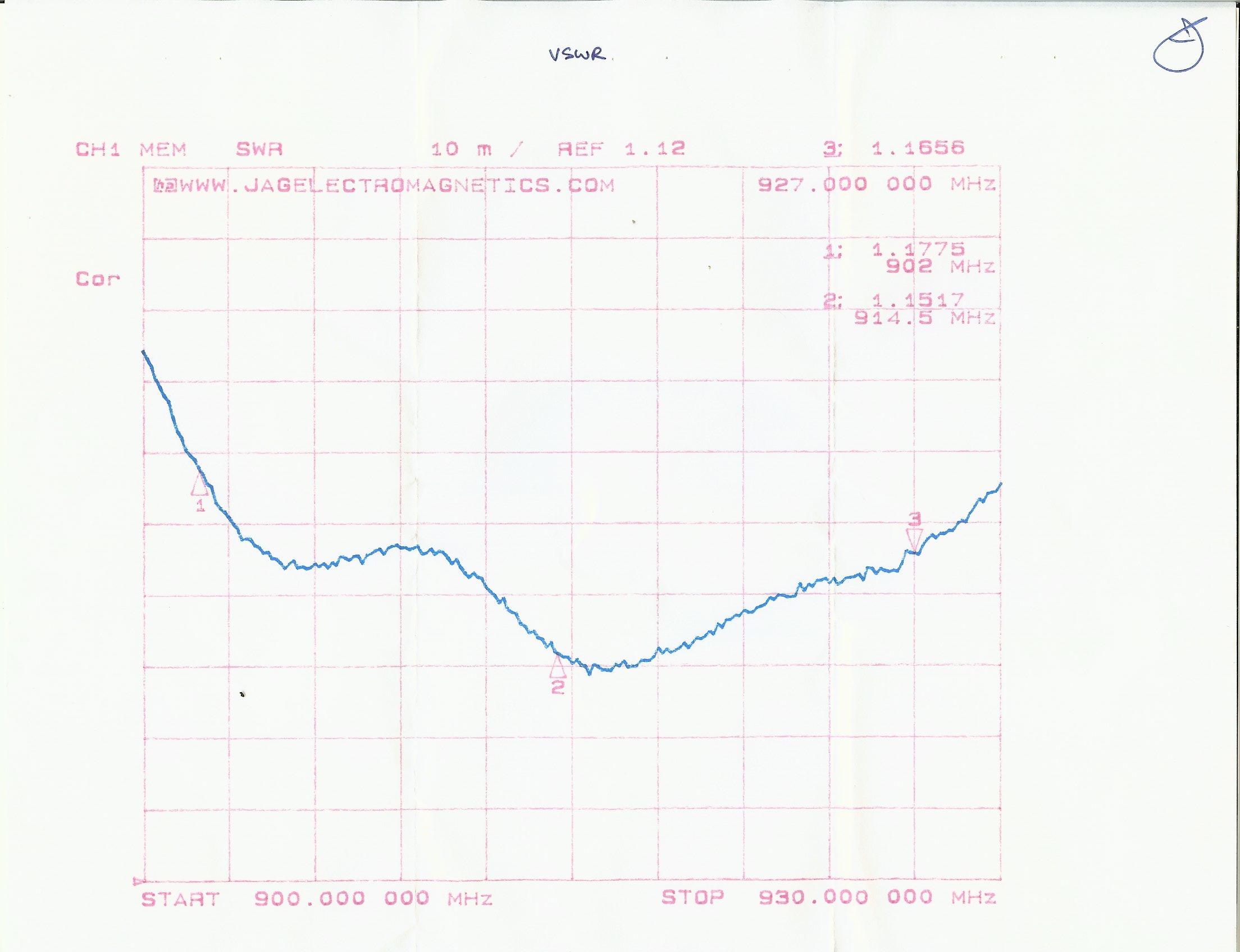
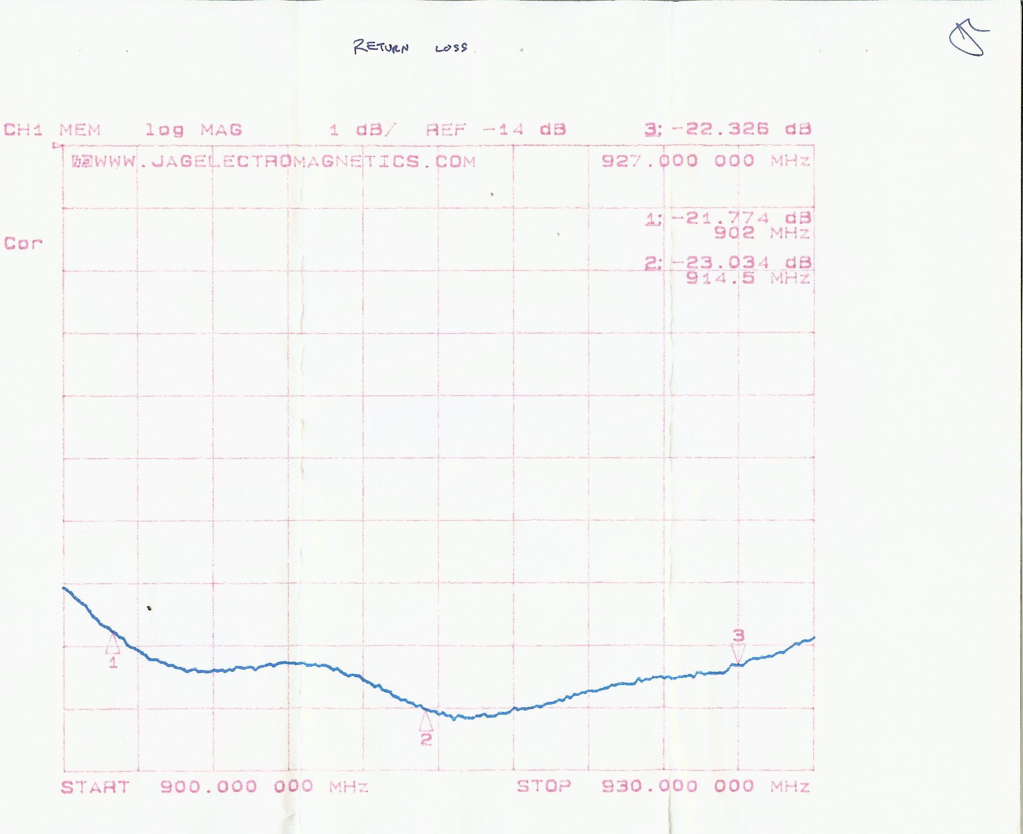
Jag's sweeps from 900 to 930 MHz show the following:
VSWR of 1.1656 at 927 MHz with an impedance of 55.025 ohms and gain of 8.325
dB for my repeaters TX.
VSWR of 1.1775 at 902 MHz with an impedance of 44.145 ohms and gain of 7.774
dB for my repeaters RX.
I am sure this will be a HUGE performance improvement over the 5/8th wave mag-mount antenna that I have been running the repeater on for years and I cannot wait to try it out on the tower.
The waiting is killing me ~ LOL.

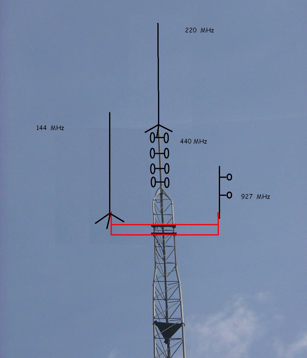
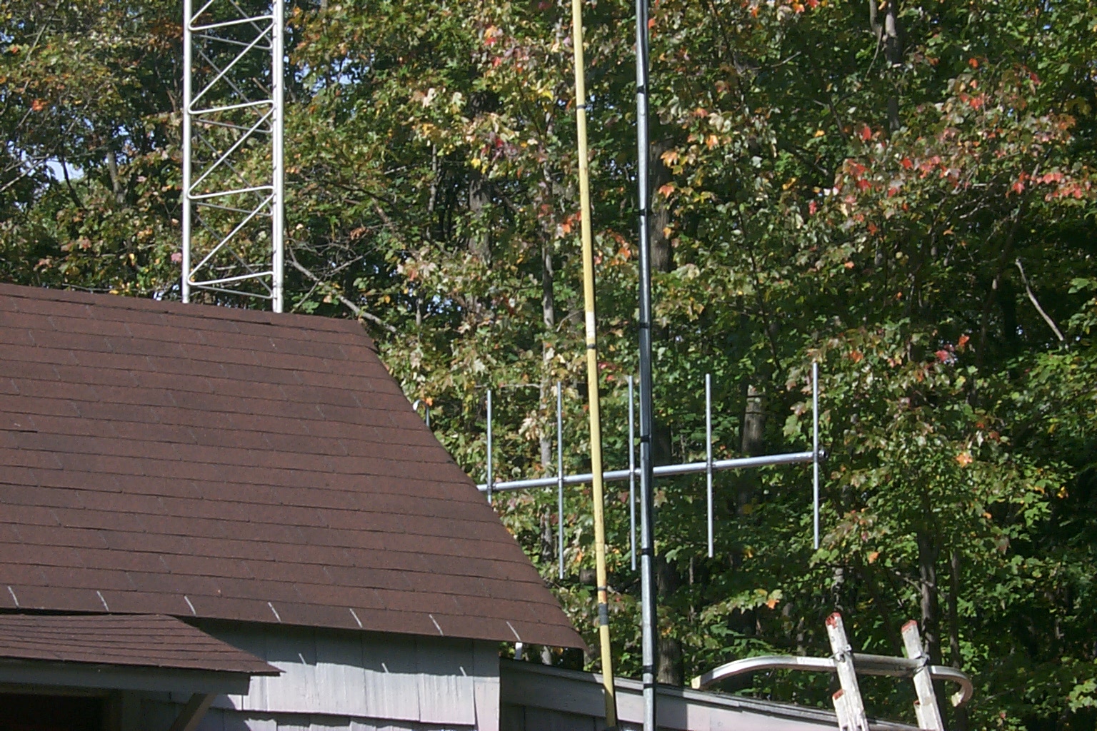
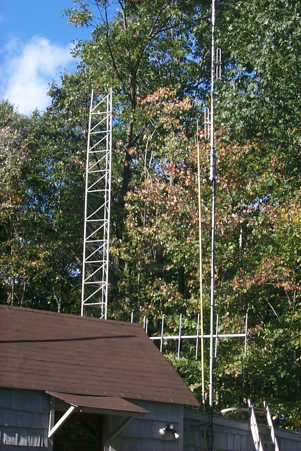
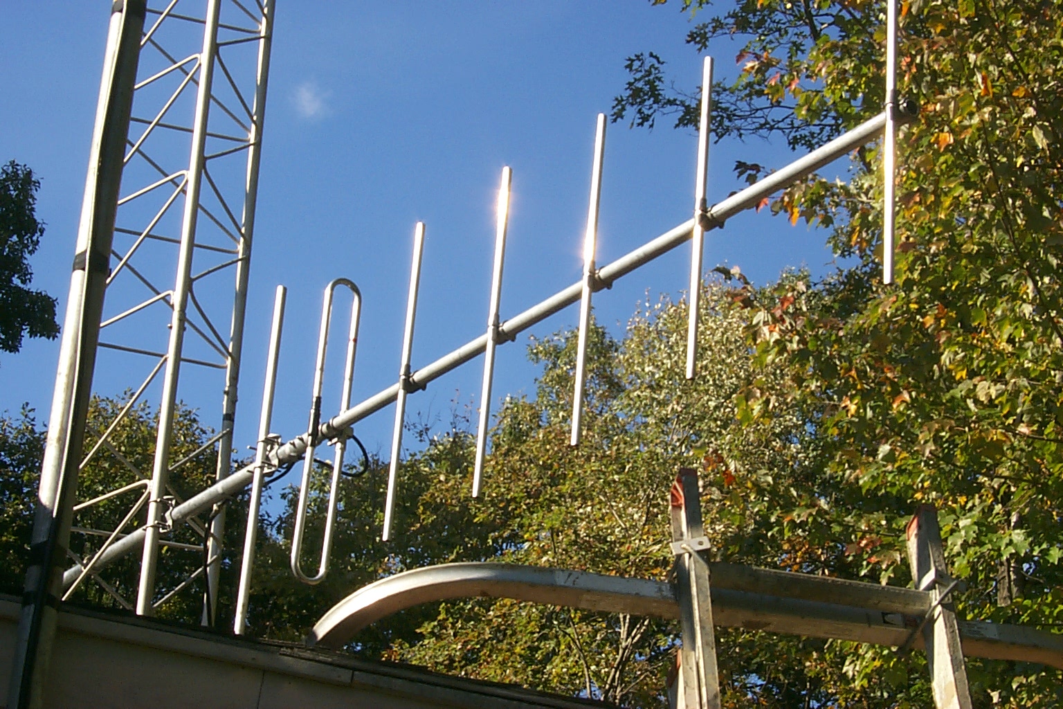
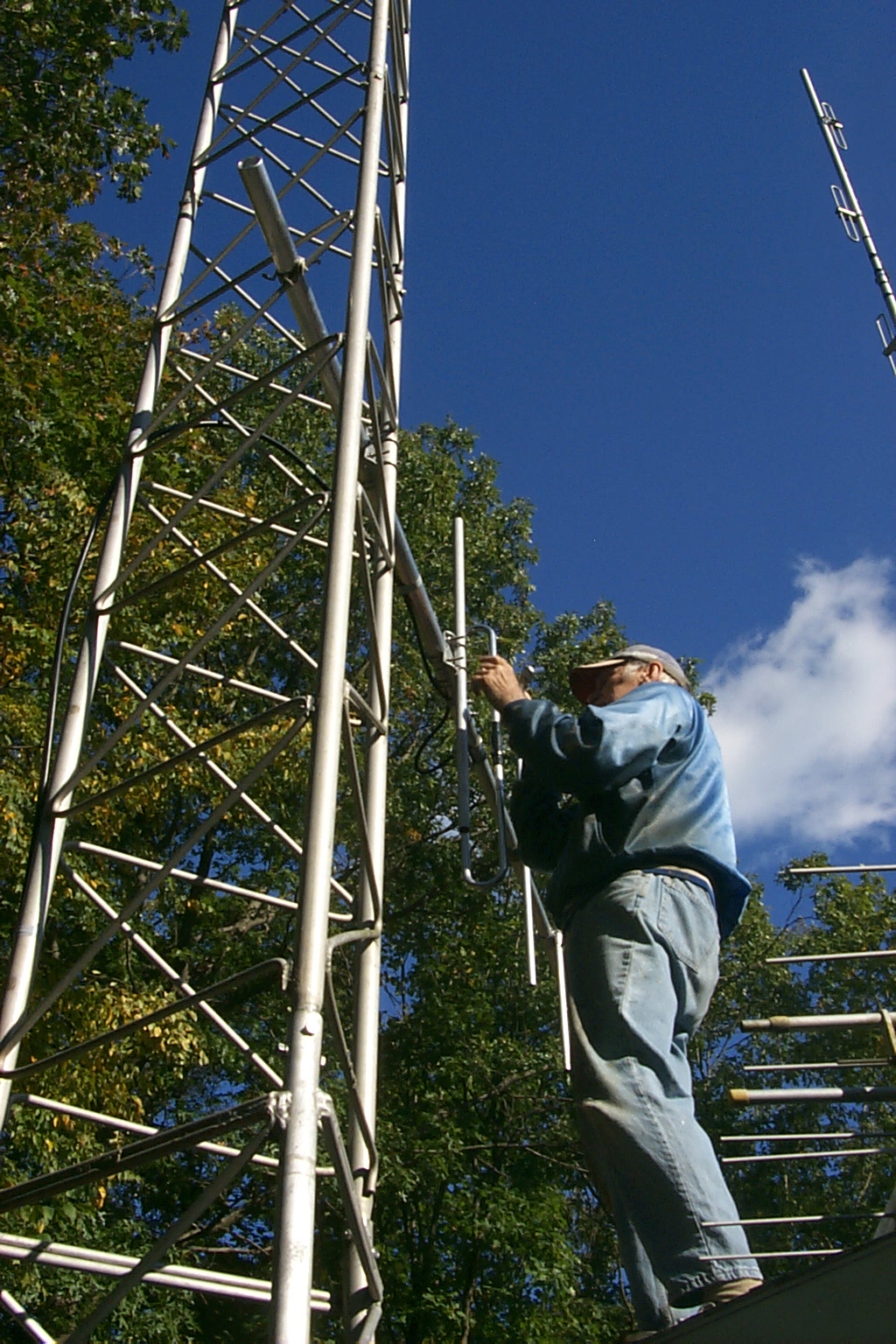
Here are a few of the different mounting locations that I have been considering for the new antennas. If all goes well with the difficult demands of my work schedule and the little vacation time I have left this year, we might be able to get all this work done and get the tower back up in October just before the snow starts flying...

Update - August 19th - 2010
I ordered a new 24 foot long piece of aluminum 6061-T6 tubing to replace the old 21 foot galvanized pipe in the top section of tower. I actually purchase two of them so I would have some stock for additional mast on a new side-arm etc. They were delivered this afternoon and I can not wait to start rebuilding the tower with this new mast.
The new aluminum pipe will eliminate the dissimilar metal issues with the galvanized pipe and the aluminum tower and the extra three feet will allow me to extend the mast out the top of the tower far enough to accommodate the new DB-408 dipoles for the 447.775 repeater. I am also going to replace the old galvanized angle iron brackets on the side of the tower with a new aluminum stand-off bracket from Heights Towers. If my work schedule and the weather cooperate I might be able to start taking all the old antennas, feed-line, and hardware off the tower tomorrow...
I have been exchanging email with the various antenna manufactures and I am narrowing down the mounting choices...
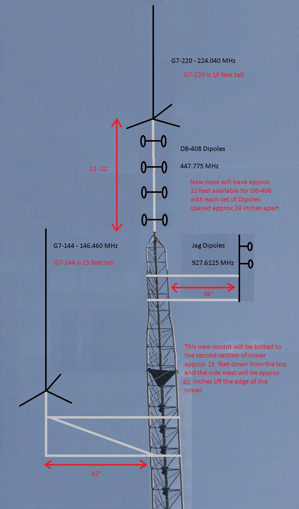
These are the new antennas being installed.
There will be approximately 11 to 12 feet of the new 24 foot long 6061-T6 aluminum mast extended through the top of the tower. The G7-220 will be mounted to the very top of that mast leaving approximately 10 to 11 feet of space on the mast for me to mount the DB-408 UHF Dipoles.
The DB-408 dipole array will be spaced 24 inches apart. (center to center of each dipole) directly below the G7-220 and above the top section of tower.
I have purchased a the Heights Tower stand-off mount that
will be mounted to the second 18" section of the tower providing a 42” mast
approximately 36” off the edge of the tower. The new stand-off will be
mounted approximately ten feet down from the top of the tower and I will
have the G7-144 mounted on the top of the stand-off and
the Jag 900 MHz Dipoles mounted upside down under the
G7-144 positioned as far off the edge of the tower as possible.
Here links to the specifications for the three antennas
that will be mounted on the tower.
http://www.repeater-builder.com/db/pdfs/db-408-data-sheet.pdf
http://www.new-tronics.com/main/html/base_model_g7-220.html
http://www.new-tronics.com/main/html/base_model_g7-144.html
(Simple diagram of my plans to mount the antennas – not to scale)
(The G7-220 is approximately 10 feet long and the G7-144
is approximately 15 feet long)
(click on images to enlarge)
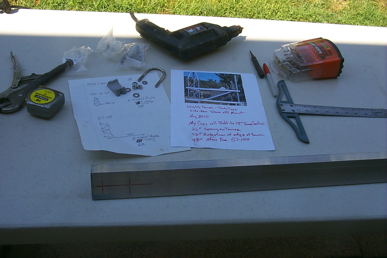
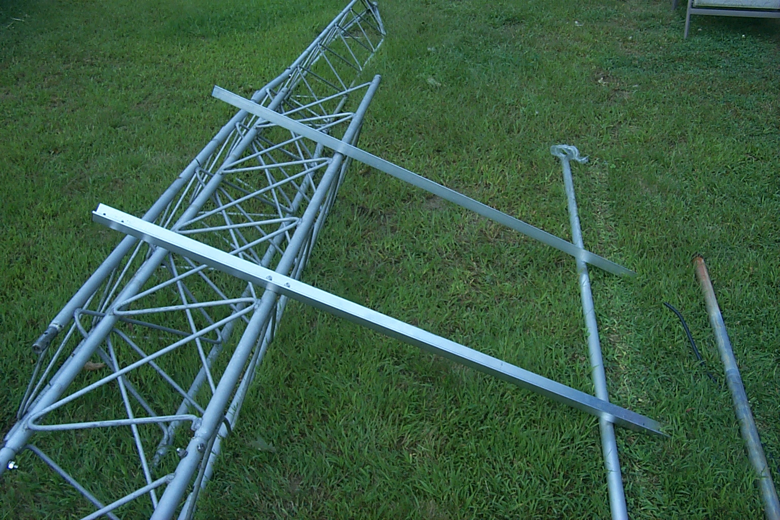
Making the first stand-off mount
Starting with just an idea in my head and looking at the picture on the Heights Tower website, I drew up some plans and Dad helped out with some math so we could fabricate our new stand-off mount. This mount will be for the new G7-144 antenna on the 146.460 repeater.


(click on images to enlarge)
We started with 25 feet of 6061-T6 aluminum unequal angle stock, 1 1/2" by 2" by 1/4" thick and 24 feet of 6061-T6 aluminum seamless pipe 1 1/2" in diameter. I also purchased a bunch of saddle clamps from DX-Engineering to clamp the angle brackets to the tower and the mast to the brackets.


(click on images to enlarge)
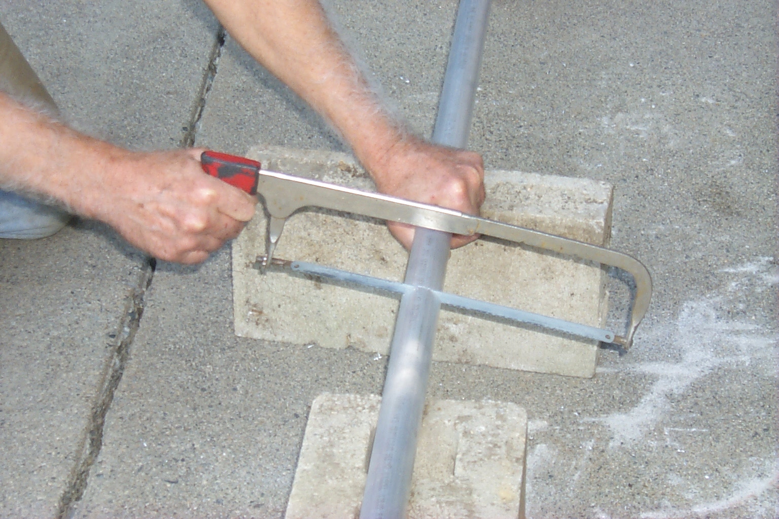
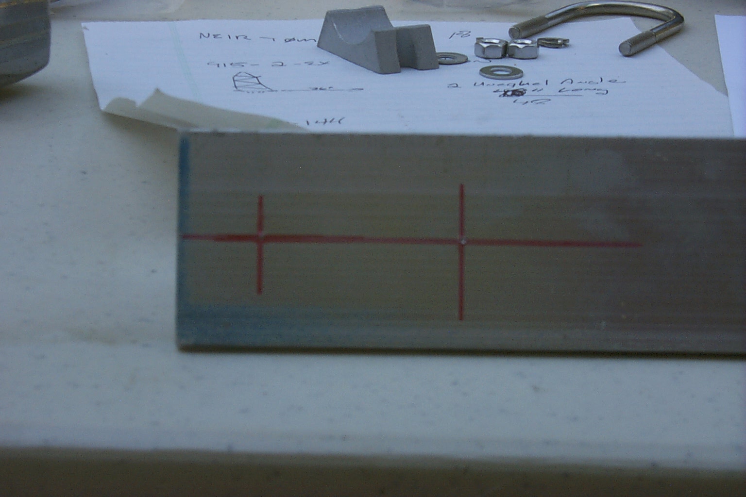
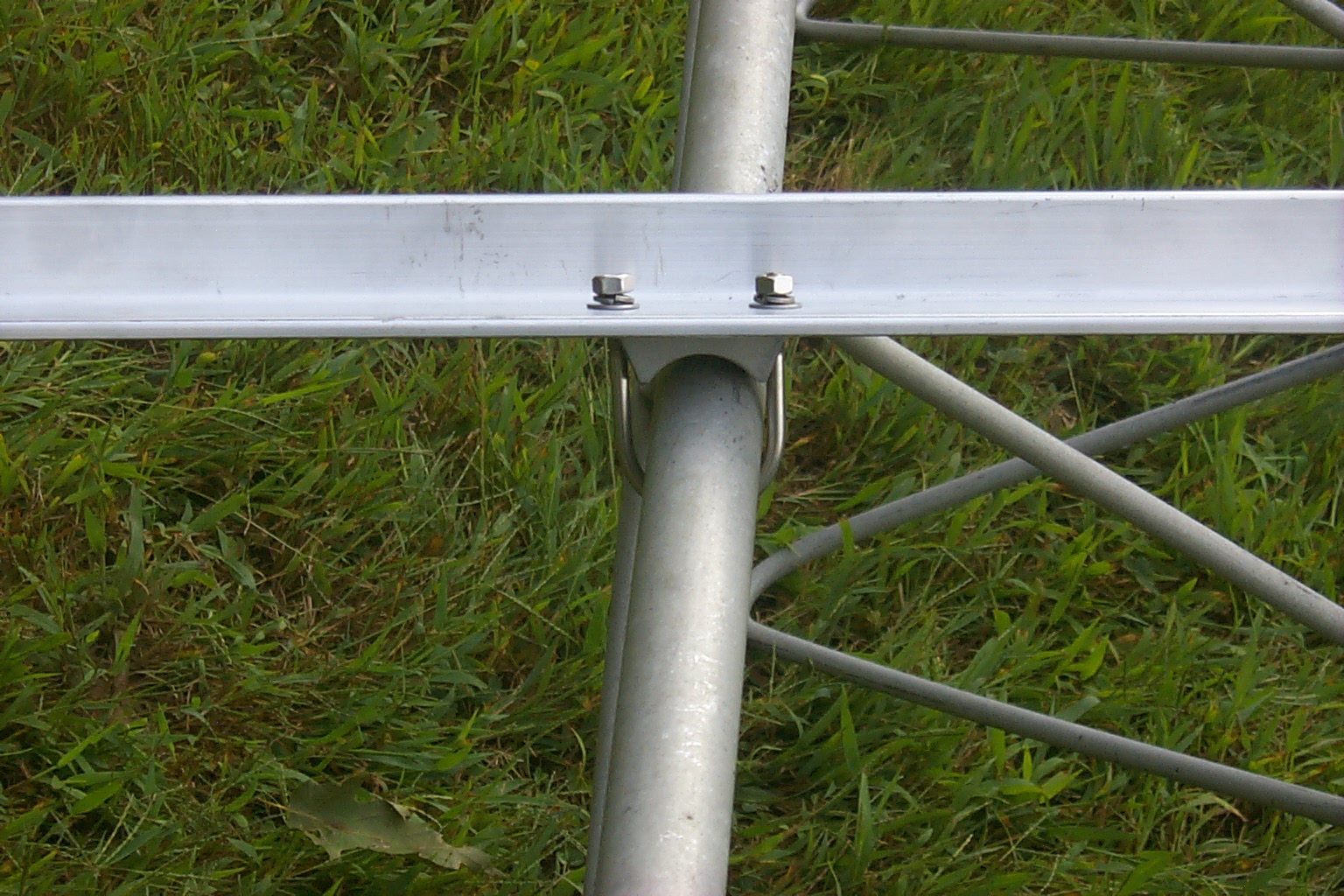
Then it was just a lot of measuring, cutting, drilling, and finally some assembly...


(click on images to enlarge)
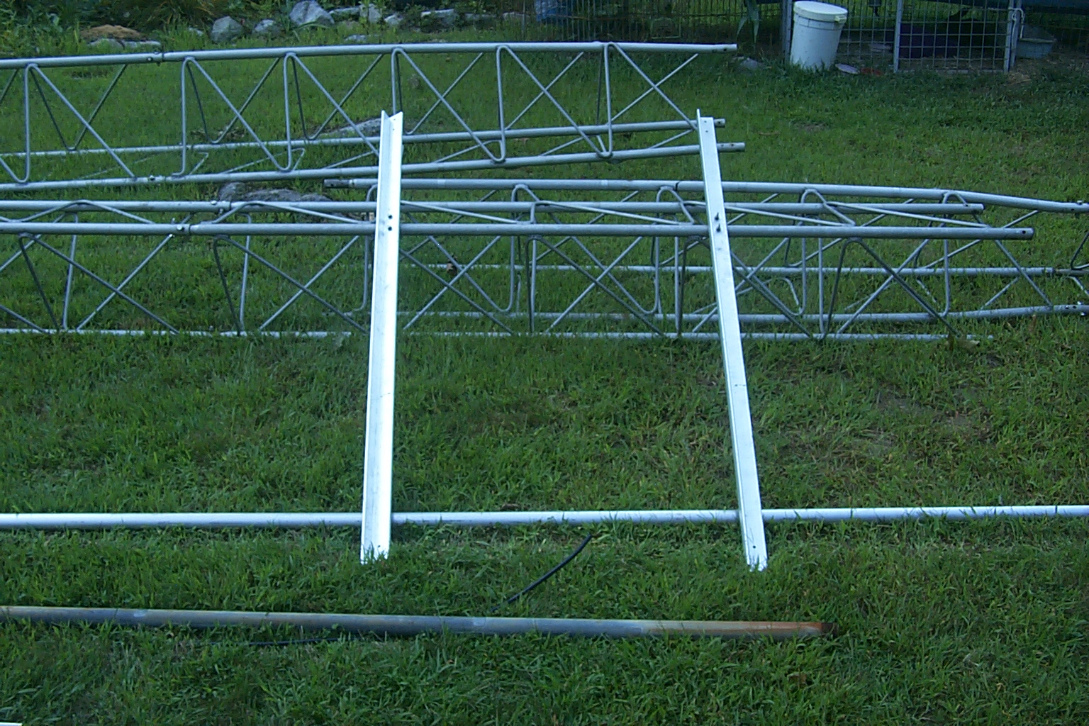
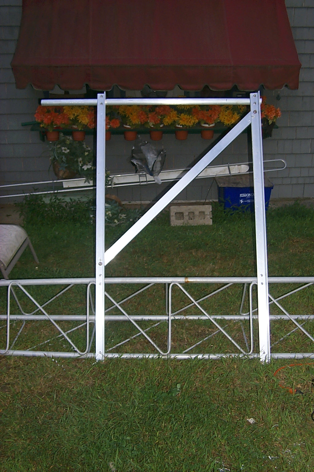
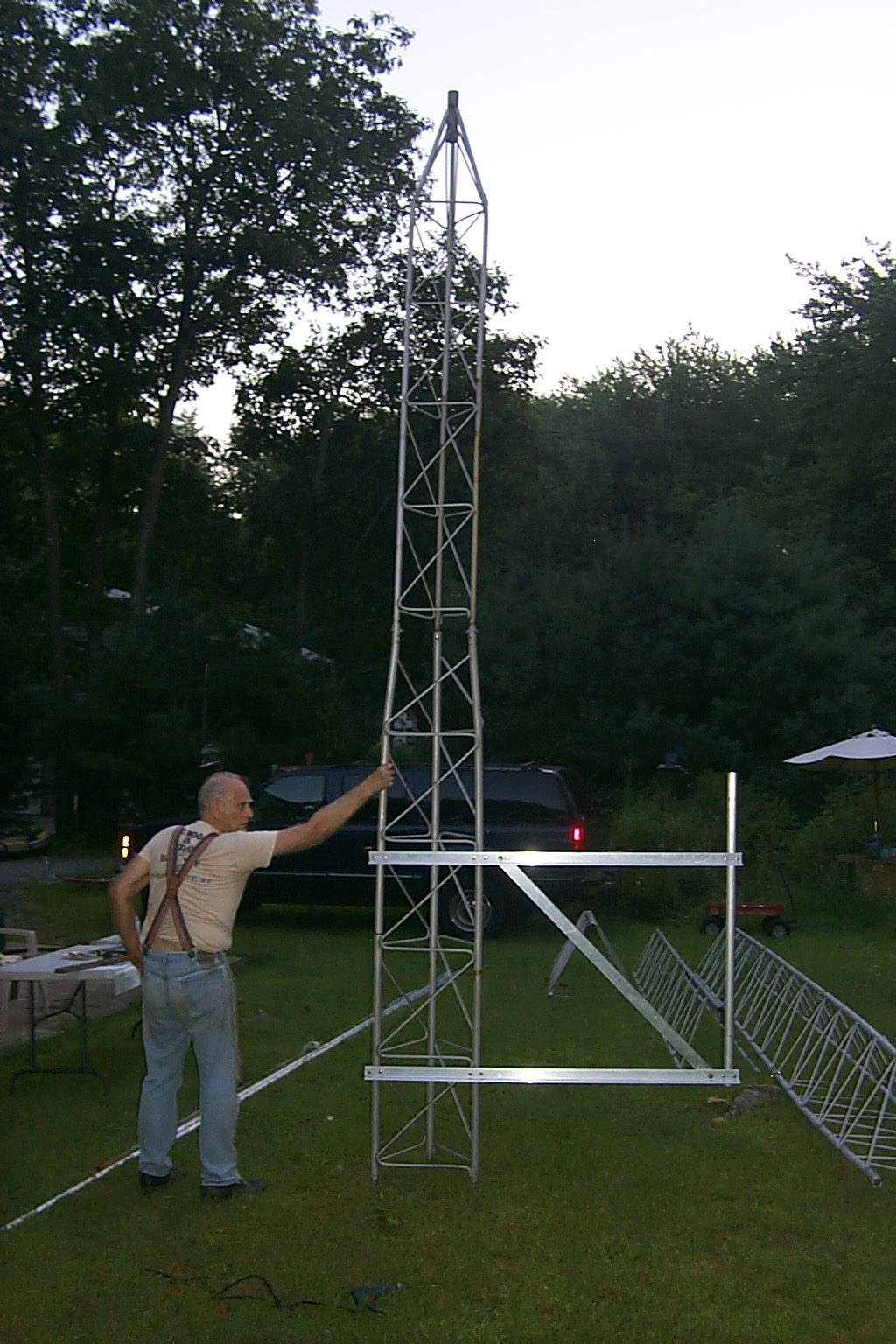
Once we had the bracket finished we mounted it to the top two sections of tower just to see how it fit and looked...
... Bill KA1VKD offered to support the tower so I could take some photos.


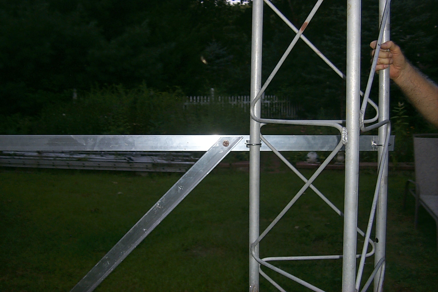
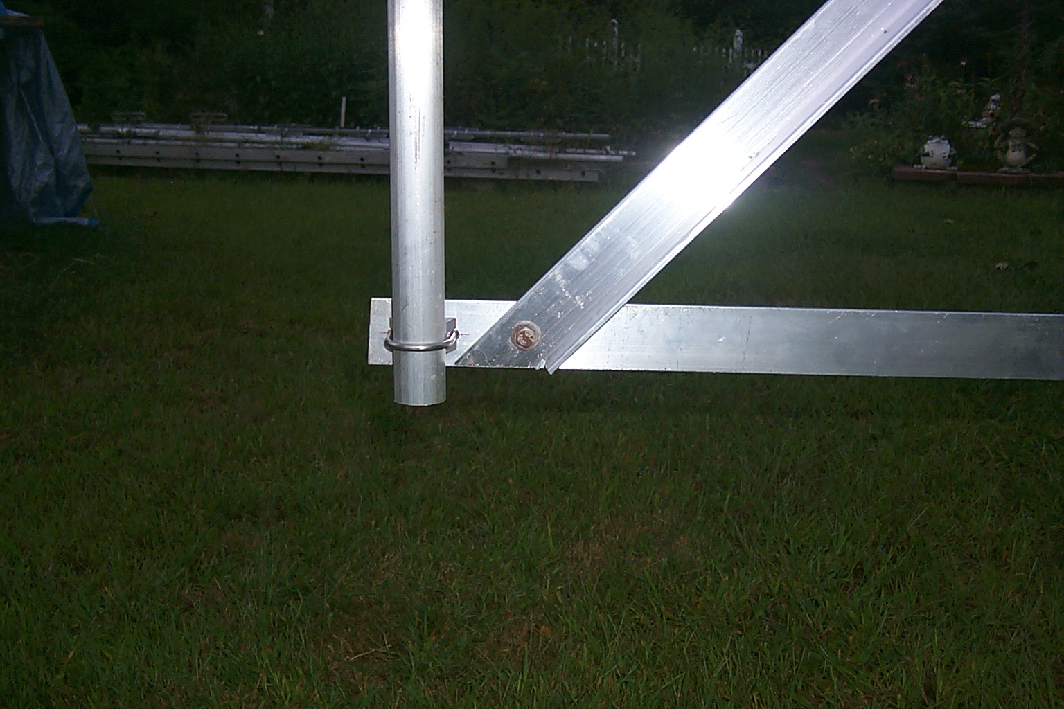
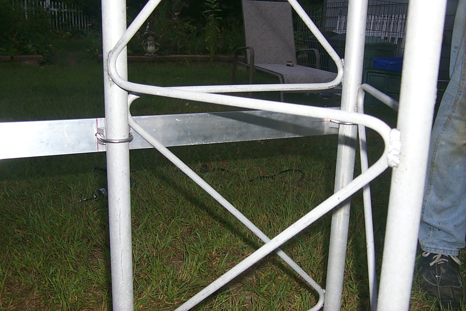
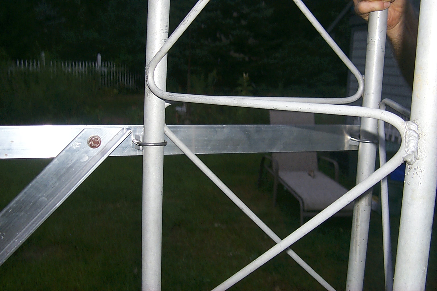
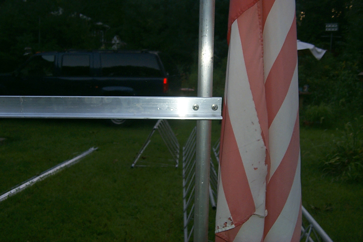
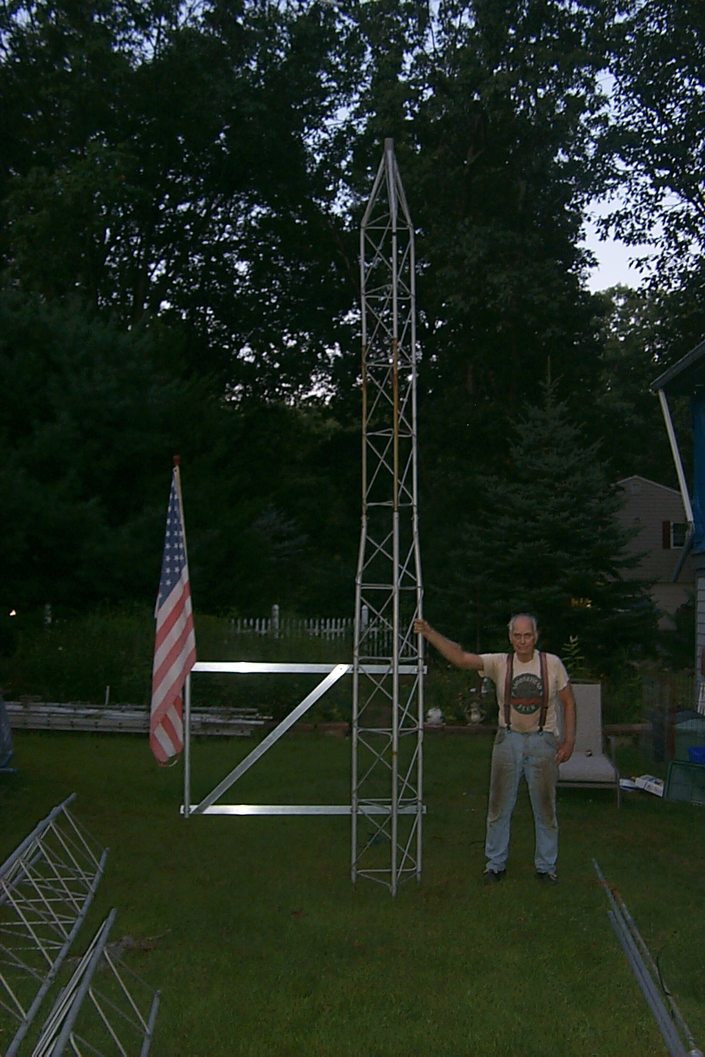

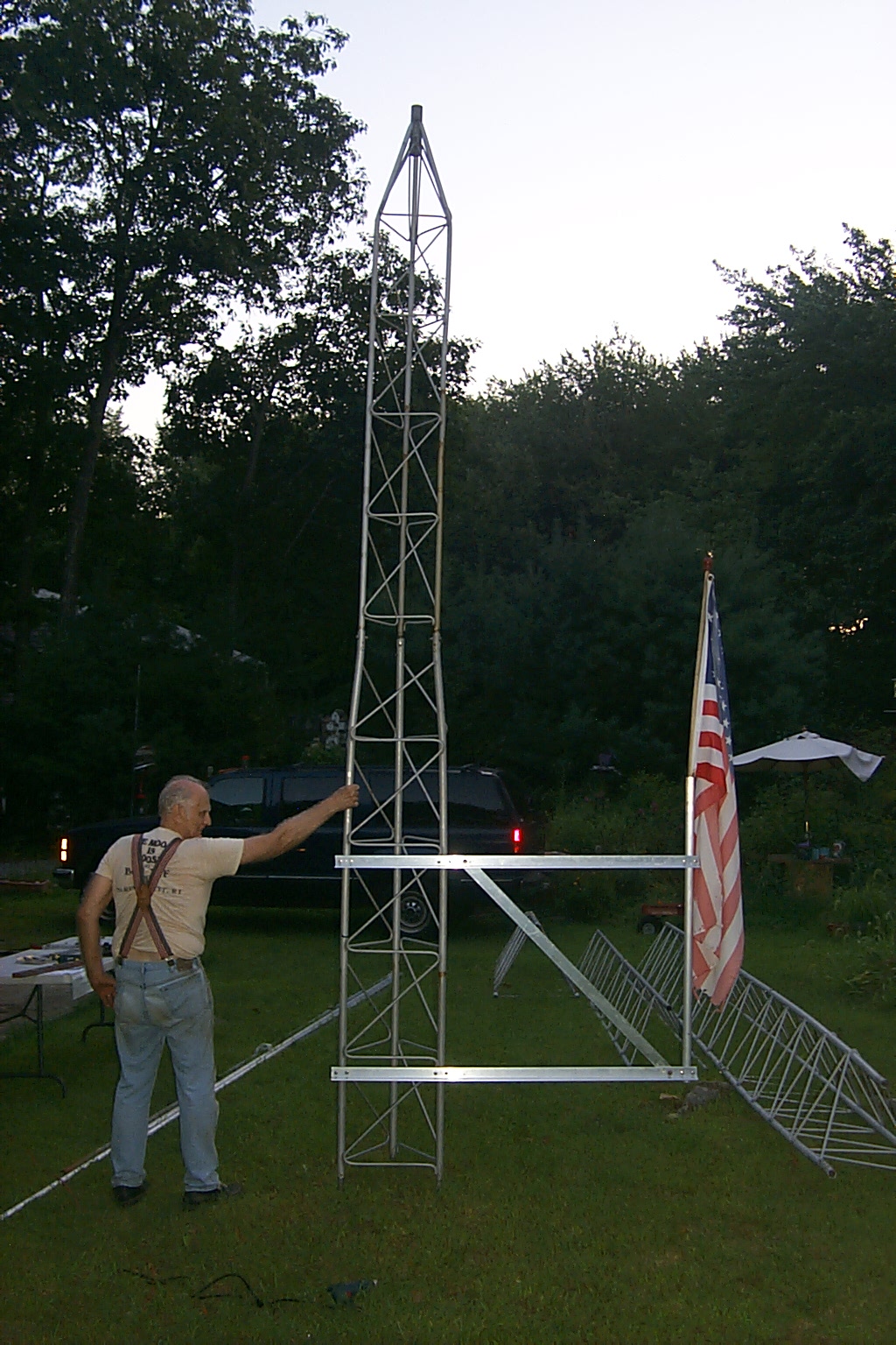
(click on images to enlarge)
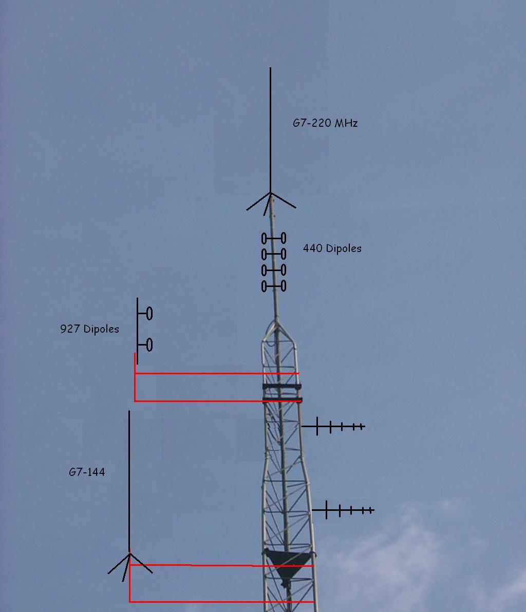
Of course now that we are making our own stand-off mounts I can customize the positions of the antennas... AGAIN!
I have decided to drop the new mount for the G7-144 a little lower on the tower and make a second mount for the JAG-915-EX dipole so the 927.6125 antenna would be much higher on the tower. Unless something else unexpected happens this diagram / layout should be fairly close to what actually goes up in the air once we crank the tower back up.
(click on images to enlarge)
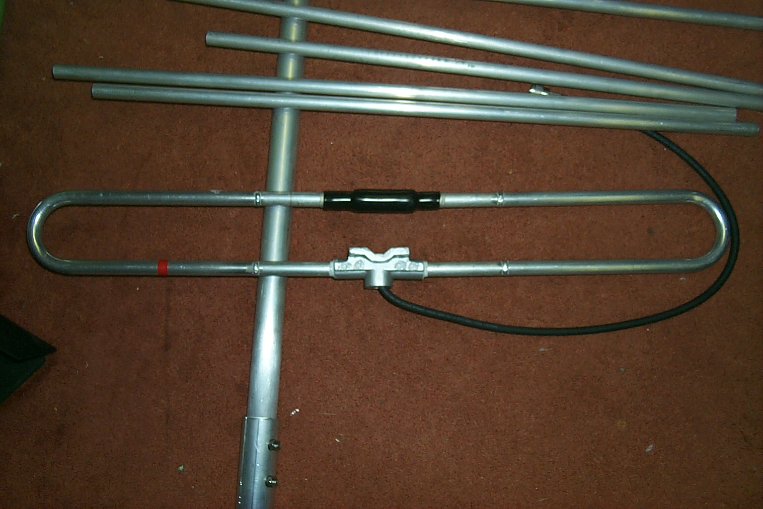
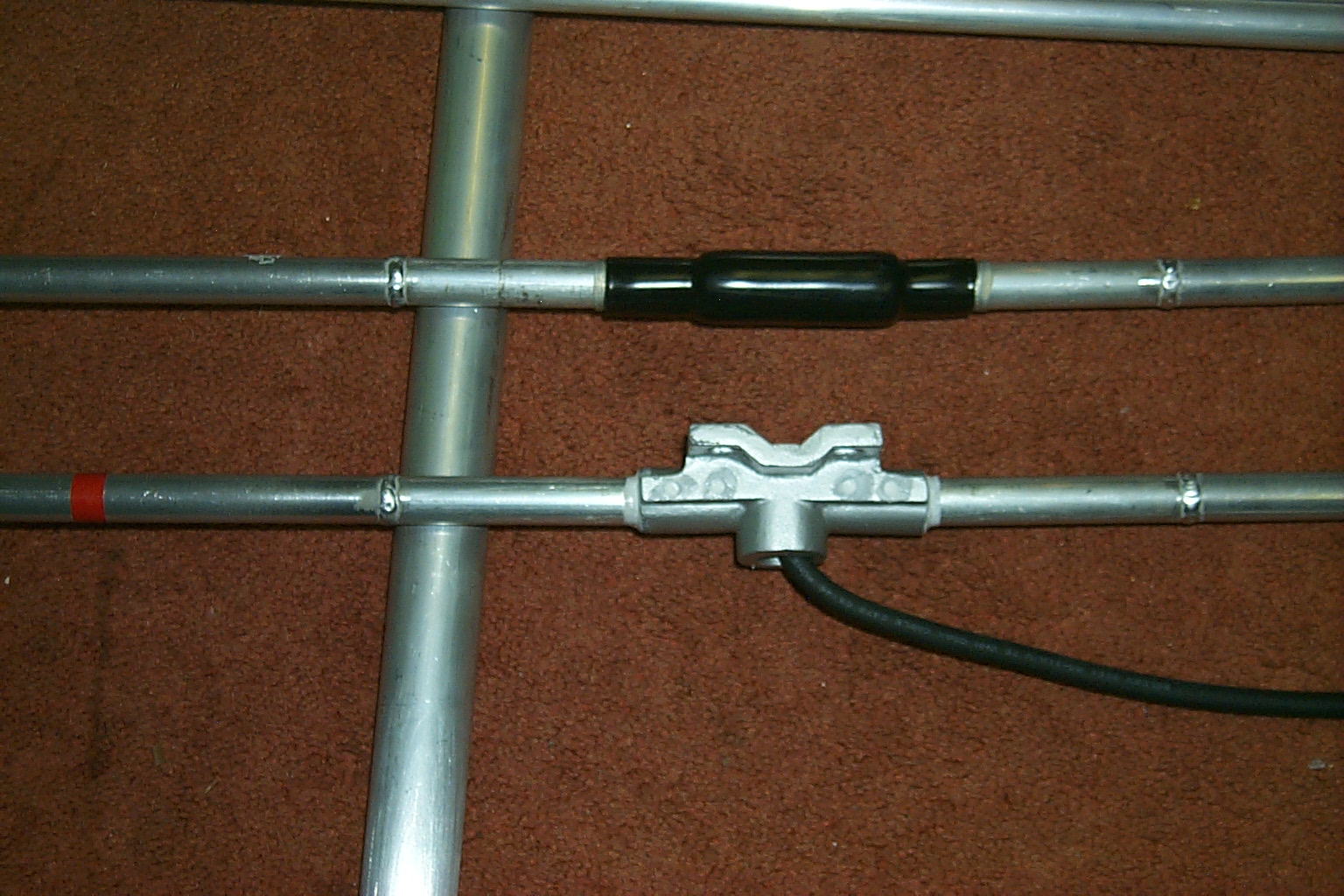
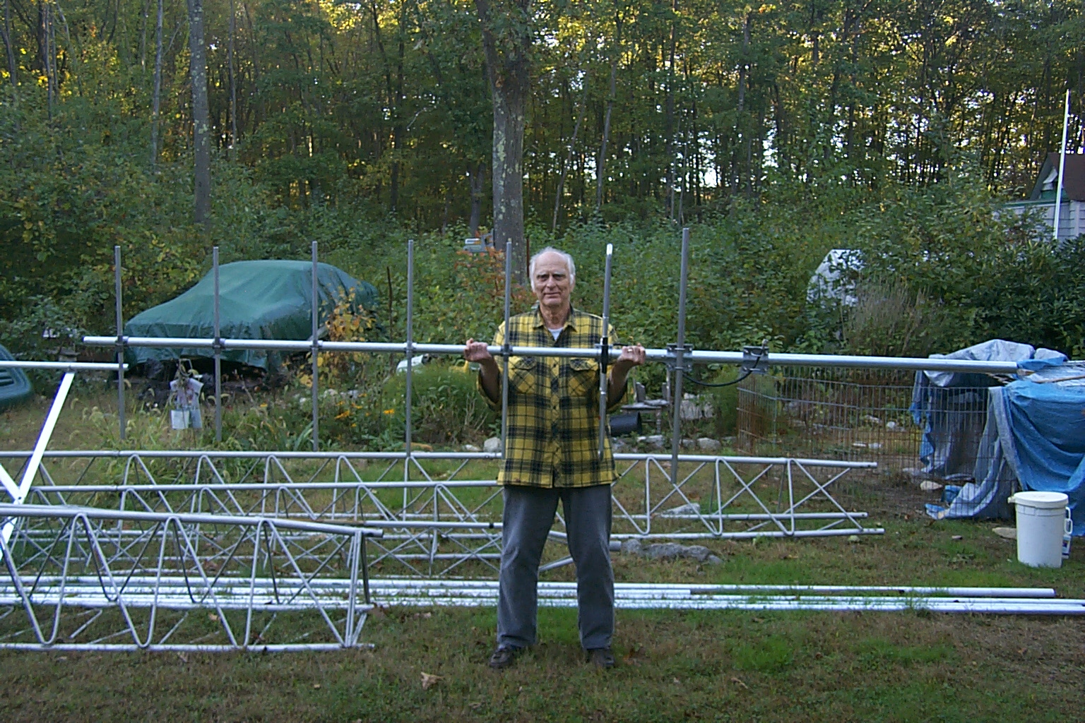
The new JAG 144-148 Yagi
While Dad was raking up the last of the ground cover I was unpacking and building my new custom JAG 144-148 MHz seven element end mounts Yagi antenna. This antenna is very impressive and much bigger than I expected. It did not look so large in the example photo that Jag had send me several weeks ago small but I am very pleased.
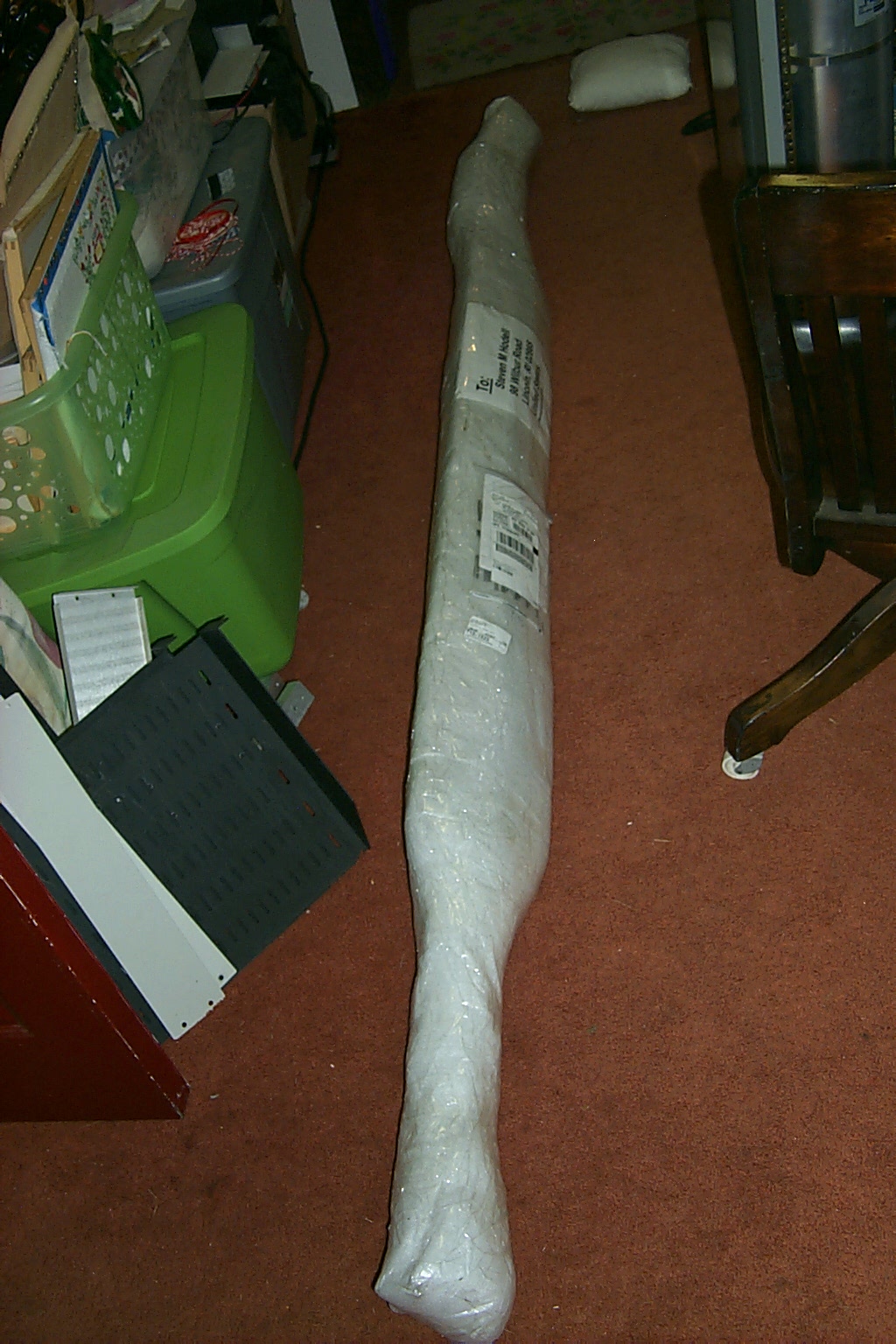
(click on images to enlarge)
Here are the detailed, hand written, instructions that Jag sent me to assemble my new antenna.
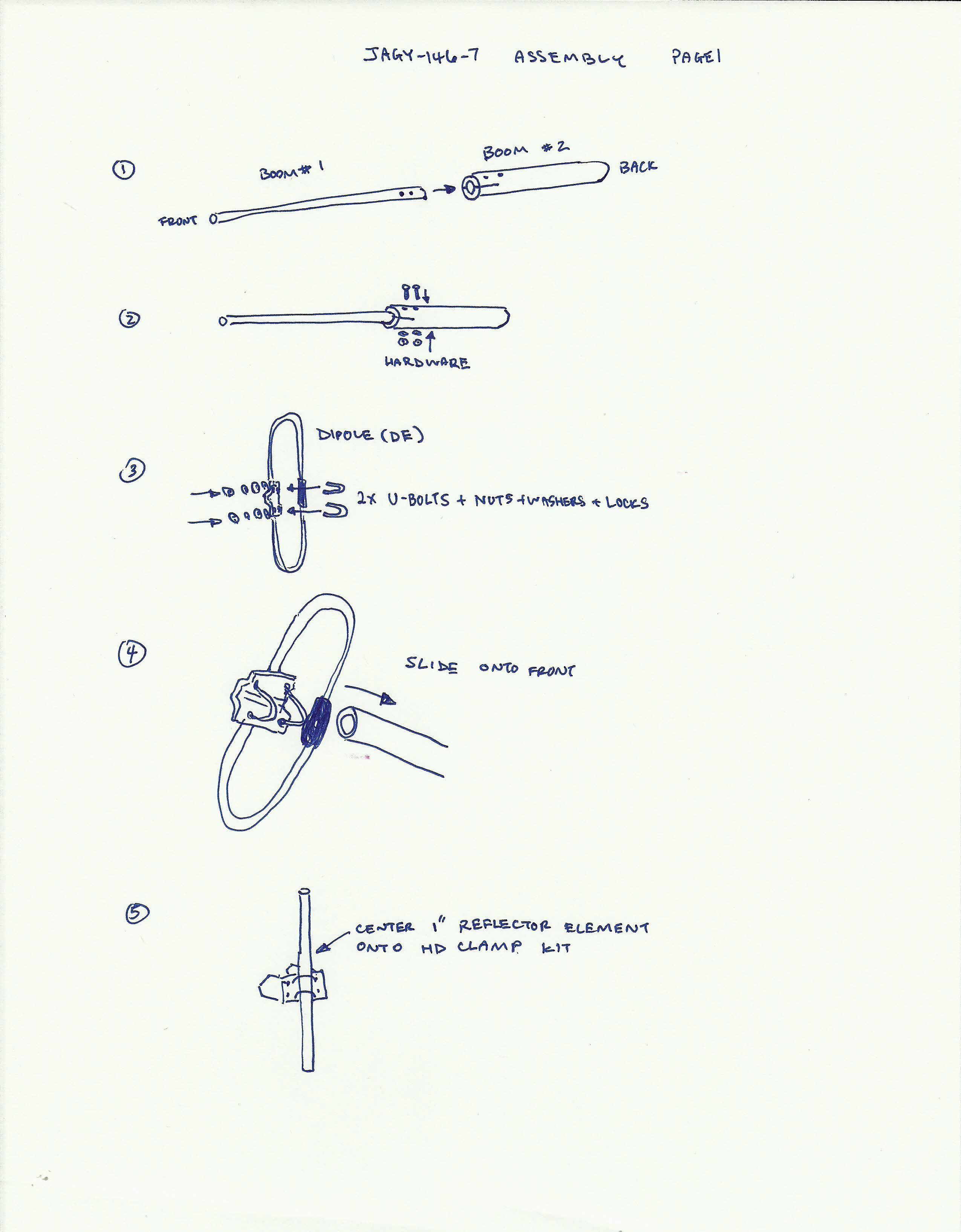
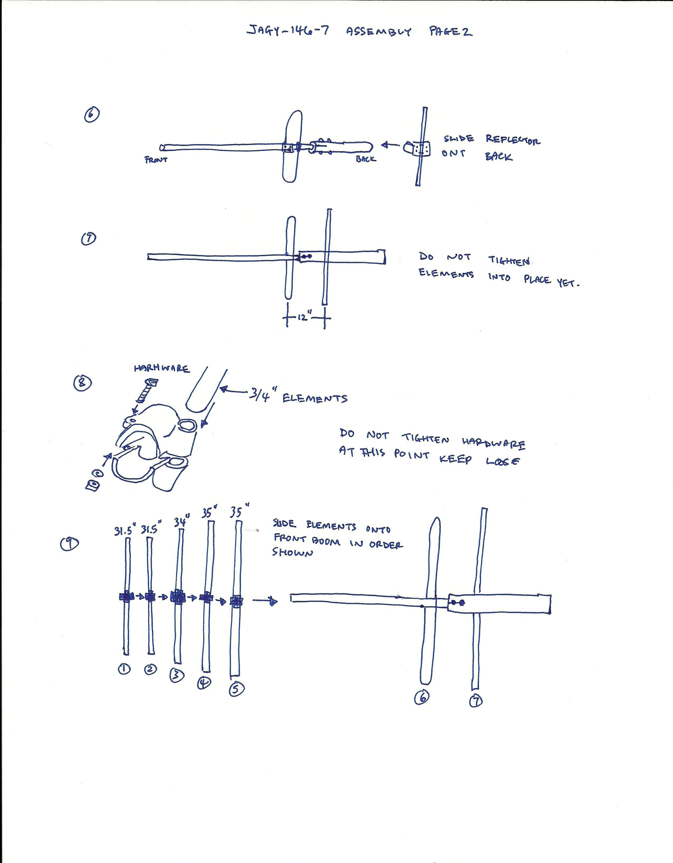
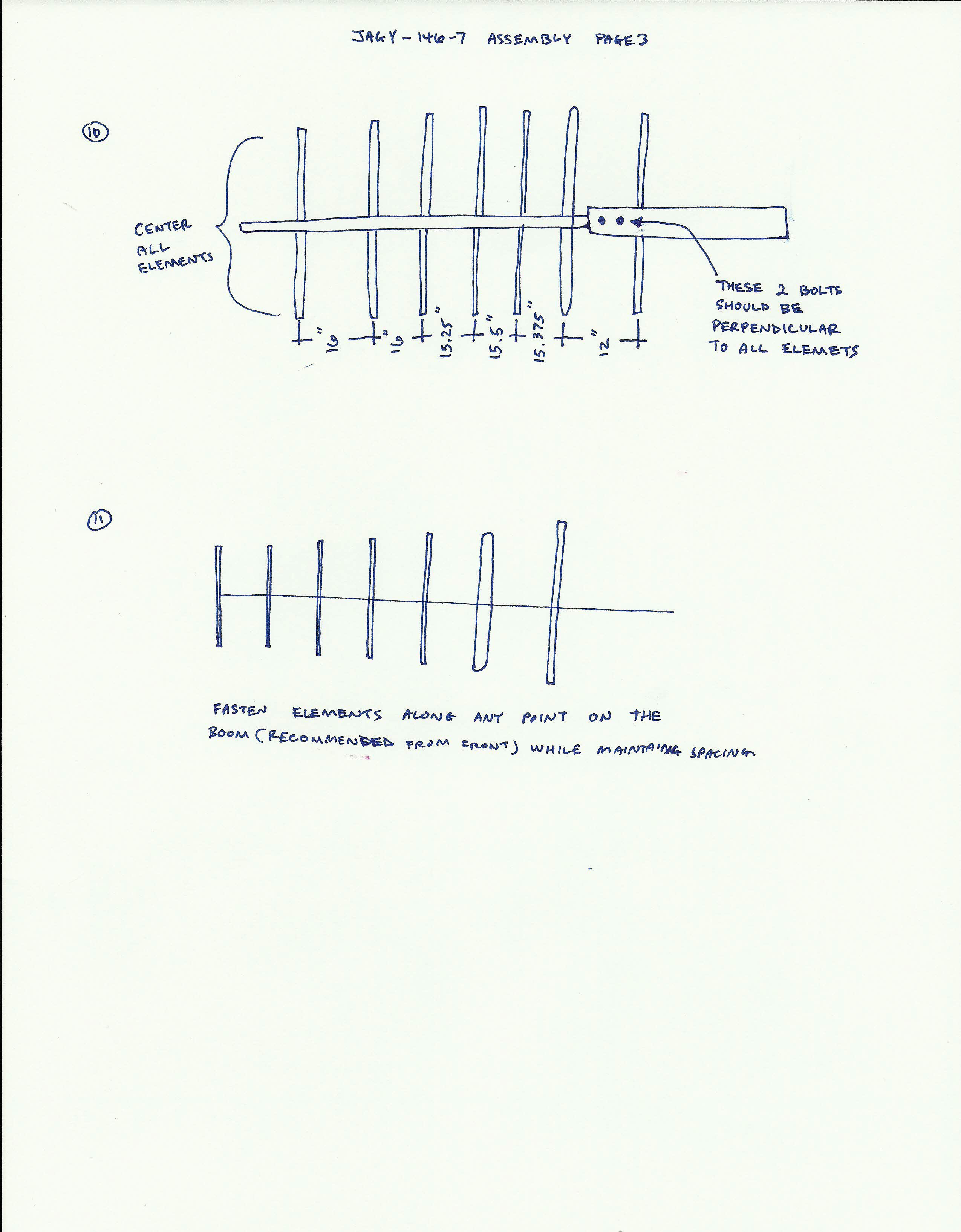
(click on images to enlarge)
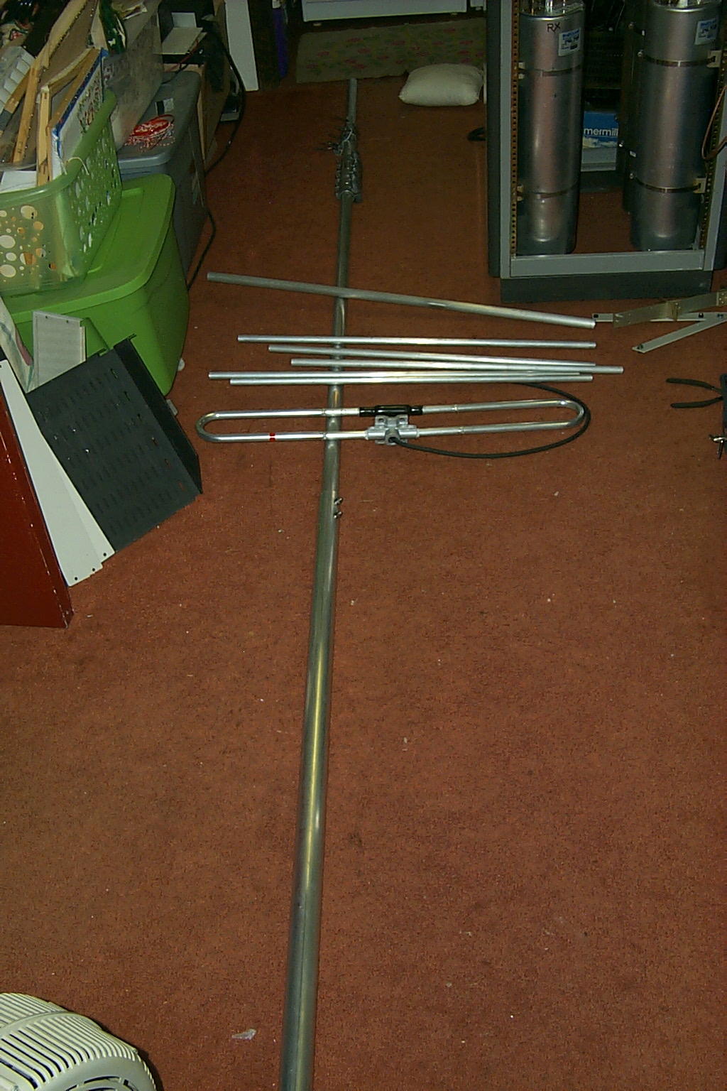
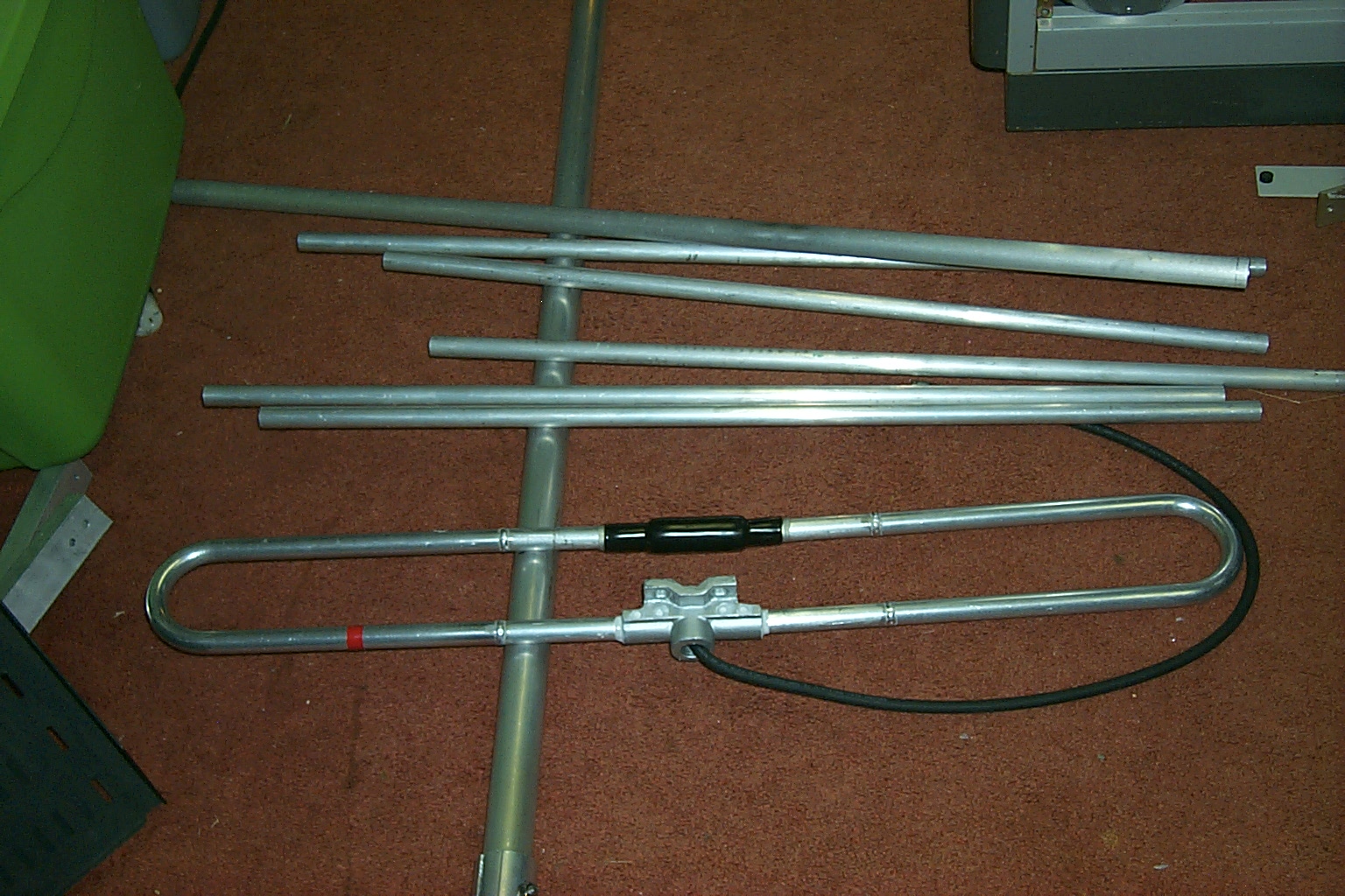
It took me a few hours to unpack and assemble the antenna and it wasn’t until after I was finished (felling a great sense of accomplishment) that I realized that I had just assembled a 13 foot long by 3 foot wide antenna on the floor of a 10 X 15 foot room!
How the hell was I going to get this thing out of the house???
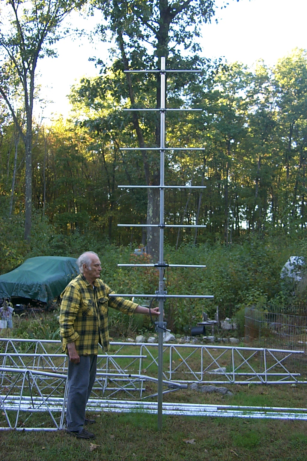
After a few minutes of beating myself up for being
so blonde I was able to jockey the antenna out into the hallway, up the stairs
to the double front doors and get outside that way…
I wonder if the Chief will be able to hear me now?
(click on images to enlarge)
Tomorrow I hope to get started by mounting my new JAG 144-148 "Thunder Boomer" on the tower, cranking up the four sections we have assembled and performing the fine tuning adjustments for the best VSWR. Jag is on "stand-bye" waiting for Dad and I to call if we have any issues getting the new end mounted Yagi dialed in on my tower.
Monday Morning October 11th
Tuning the JAG 144-148 "Thunder Boomer"
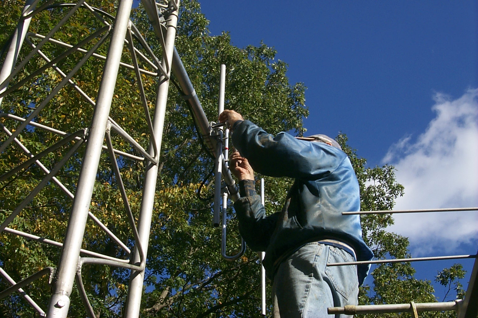
Monday morning the weather was perfect and Dad & I got an early start. We mounted the new JAG 144-148 MHz seven element end mounted Yagi on the tower and cranked the tower up so we could fine tune the new "Thunder Boomer".
(click on images to enlarge)
We only four sections (half the tower) we are able to crank the tower up and down very easily which allowed us to work on the new JAG antenna down on the ground but crank it up for the VSWR sweeps. In the test location the antenna was only 12 feet off the ground so Dad was also able to stand on the repeater shed and make small adjustments to the various elements as well.
(click on images to enlarge)
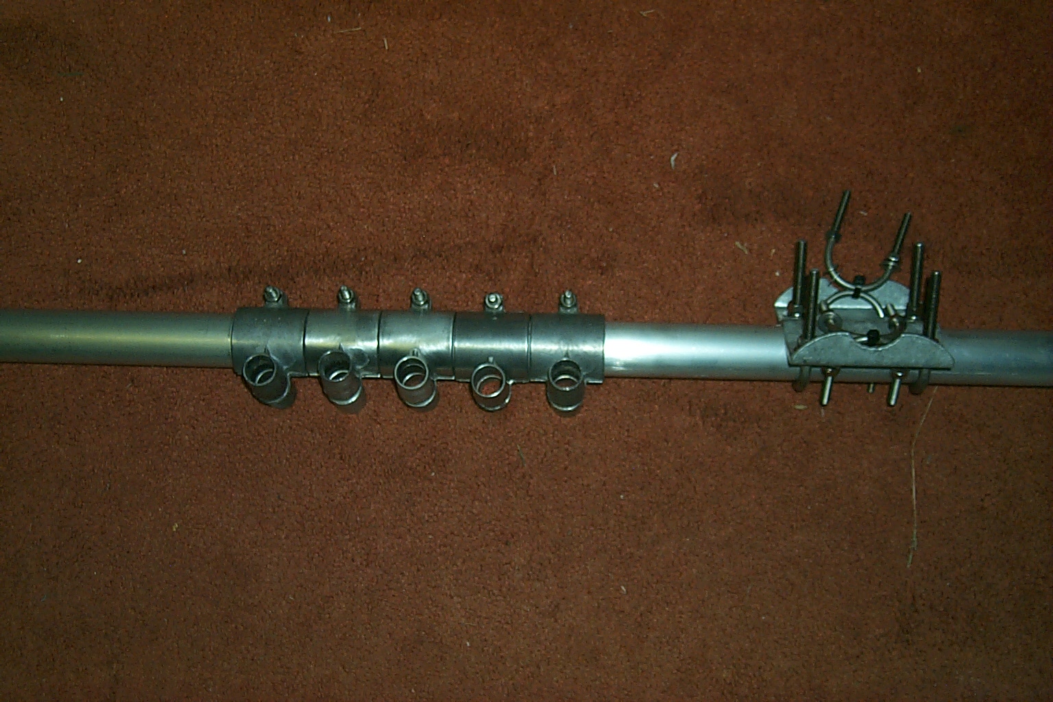
Working with Jag via email, we got the initial rough tuning by adjusting the spacing between Element No. 1 and Element No. 2 at the end of the boom and then dialed in the fine tuning matching the "Thunder Boomer" to my tower by adjusting the spacing between the Driven Element and the Reflector. In this series of VSWR Plots you can see the antenna moving towards the desired frequency as we made the adjustments.
(click on images to enlarge)
This is the last VSWR Sweep of the antenna in the test position; I will post the results of VSWR measurements when the antenna in mounted in the final position and the whole tower has been cranked back up.
| FREQ | Watts Fwd | Watts Rev | VSWR |
| 143.50 | 40 | 4.4 | 1.99 |
| 144.00 | 50 | 4.8 | 1.90 |
| 144.50 | 70 | 5 | 1.73 |
| 145.00 | 80 | 4 | 1.58 |
| 145.50 | 82 | 2.6 | 1.43 |
| 146.00 | 86 | 1.2 | 1.27 |
| 146.50 | 86 | 0.5 | 1.17 |
| 147.00 | 84 | 0.6 | 1.18 |
| 147.50 | 82 | 1.5 | 1.31 |
| 148.00 | 80 | 3 | 1.48 |
| 148.50 | 80 | 5 | 1.67 |
Back to Tower History Home Page
North 80 Foot Repeater Tower Main Page
East 38 Foot Repeater Tower - West 48 Foot VHF / UHF Tower
Return to the KA1RCI Repeater Network Home Page
This page was last updated on
02/13/2011 and it has been viewed times.
Send mail to [email protected] with questions or comments about this web site.
Copyright 1995-2011 Steven M Hodell
Copyright in these pages, in the screens displaying the pages and in the information, materials and other content contained in this web site is owned by Steven M Hodell unless other wise indicated and is protected by U.S. and international copyright laws and treaties. The information, materials and other content of this web site may not be copied, displayed, distributed, downloaded, licensed, modified, published, reposted, reproduced, reused, sold, transmitted, used to create a derivative work, or otherwise used for public or commercial purposes without express written consent.