Established 1984
The North 80 Foot Repeater Tower
Putting it all back together - Fall 2010
Monday Afternoon October 4th
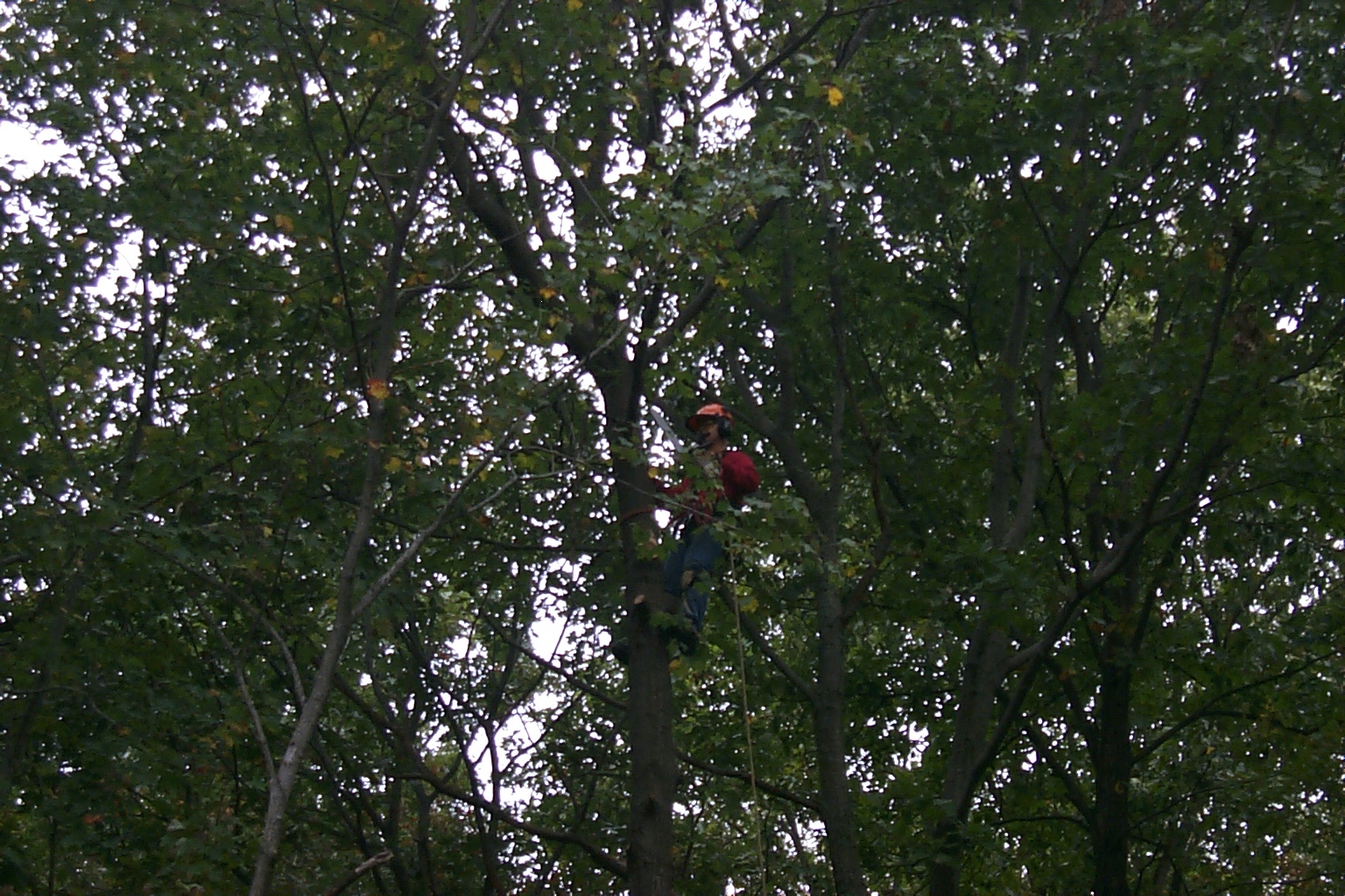
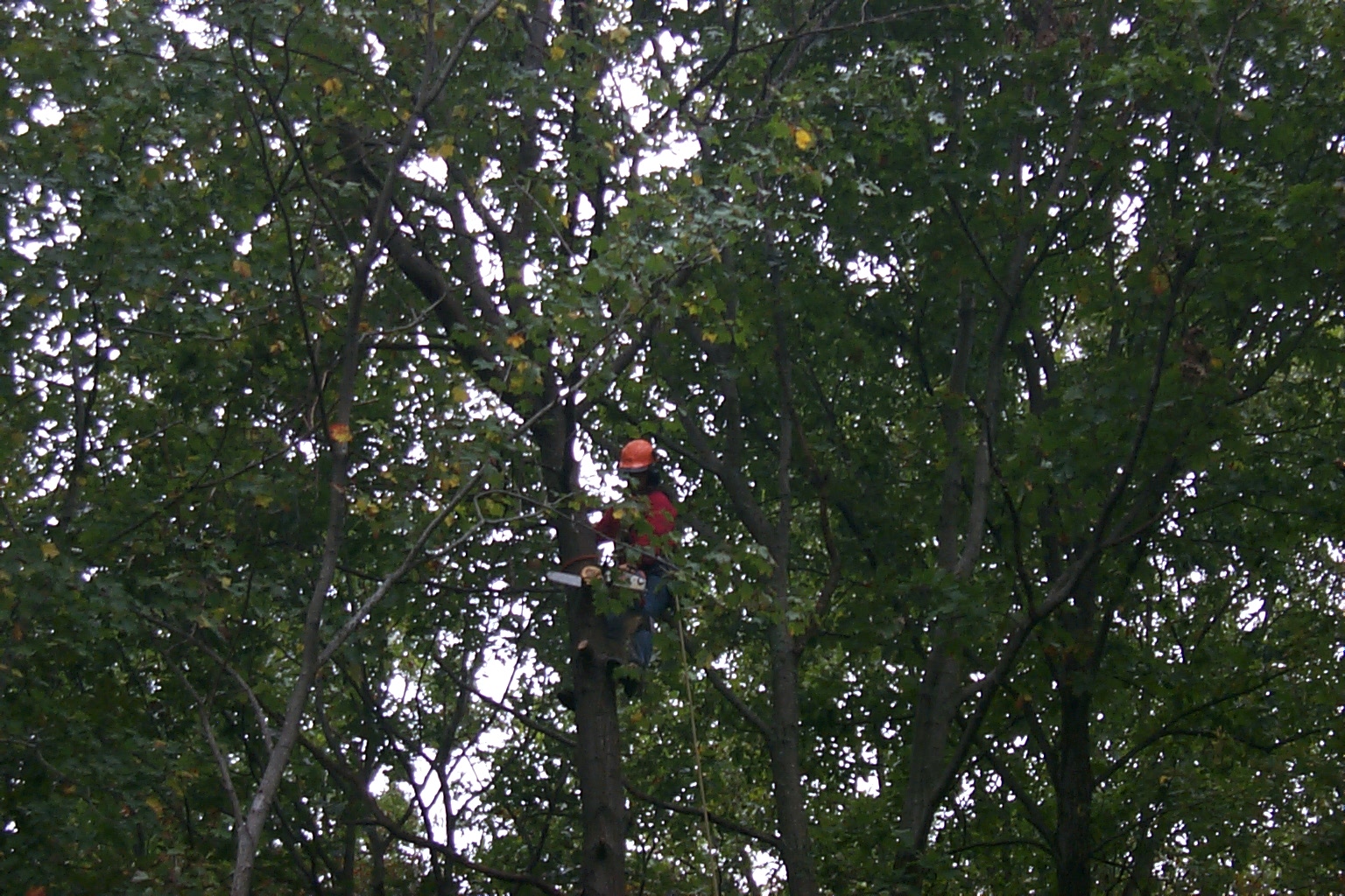
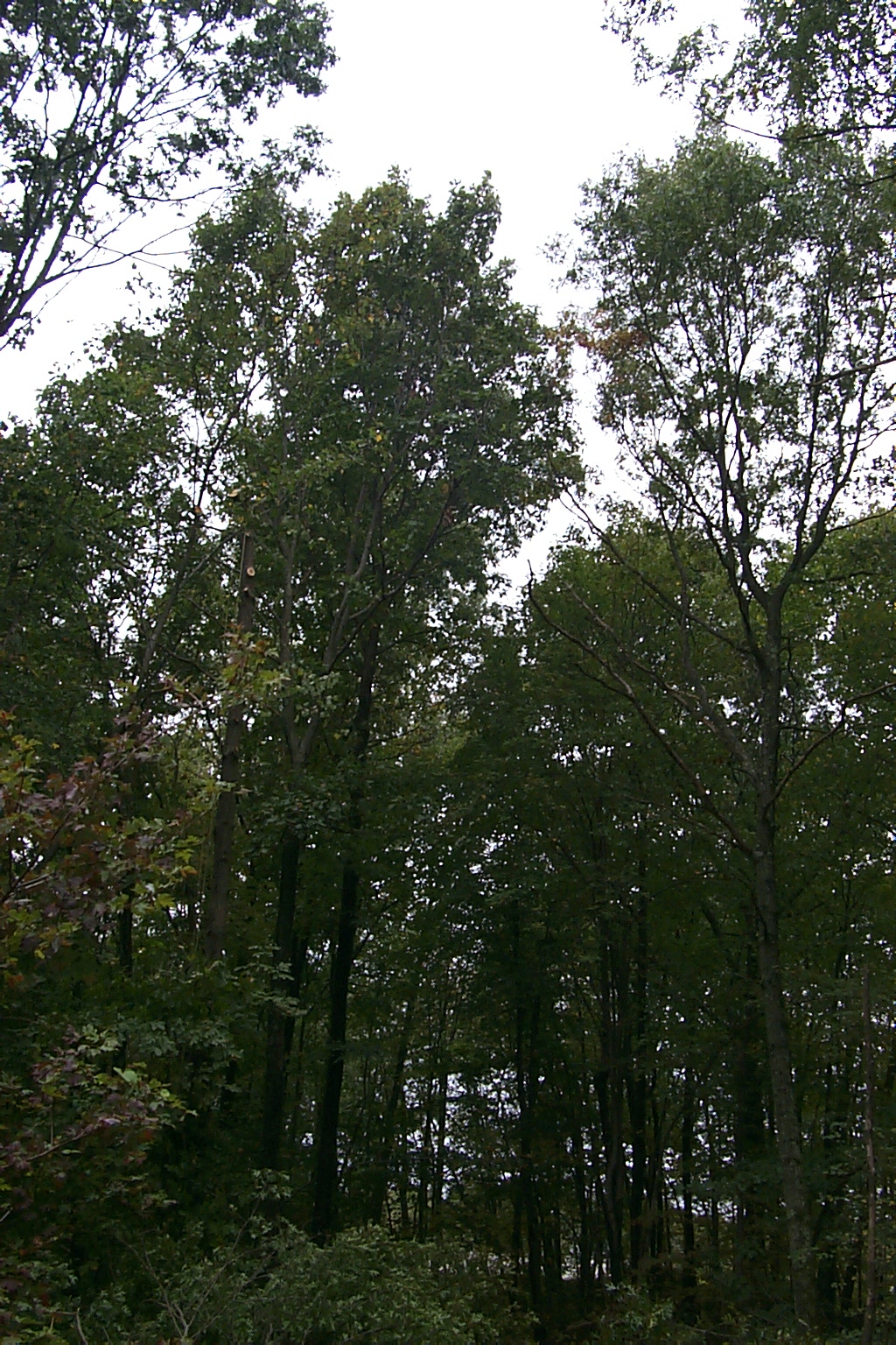
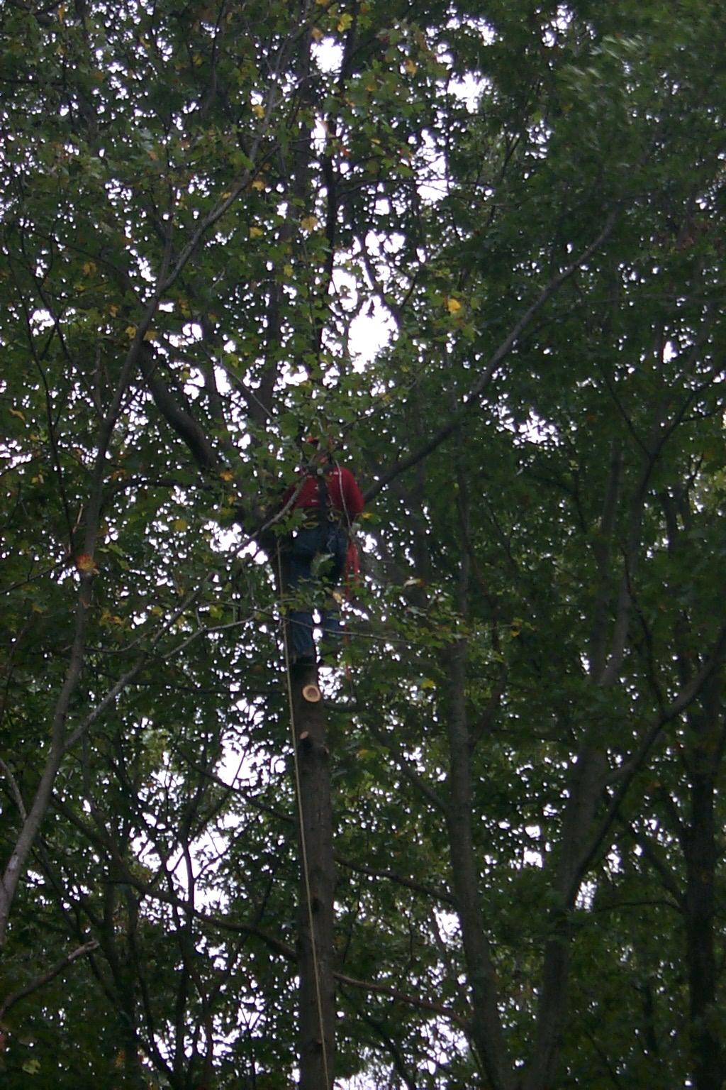
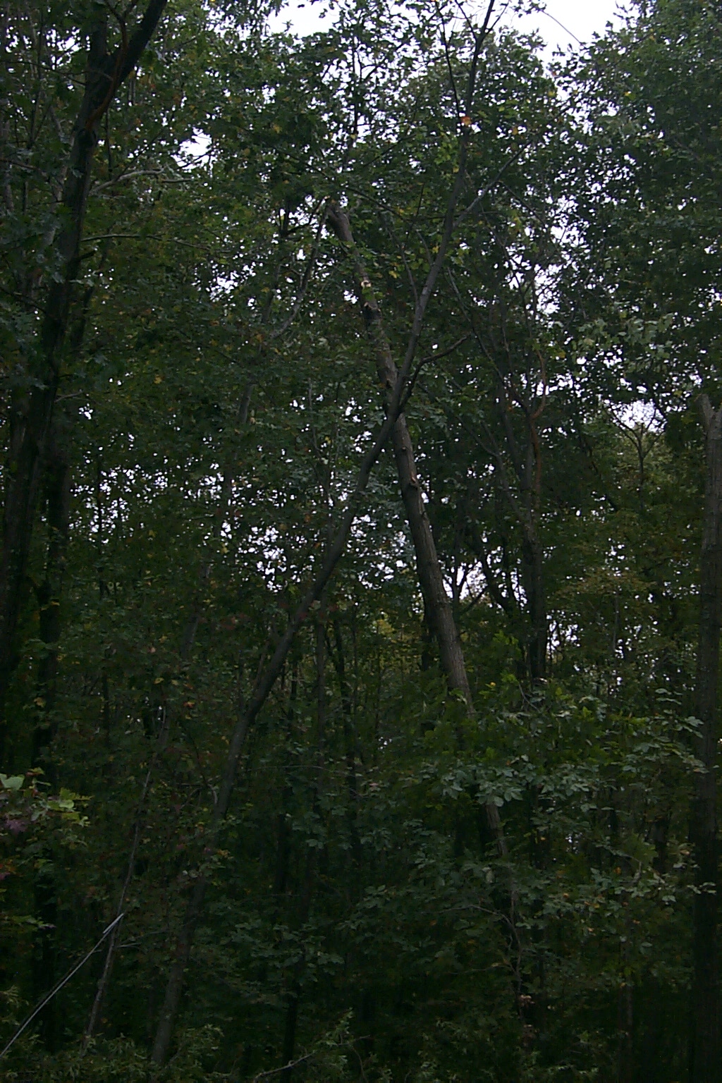
!!! Timber !!!
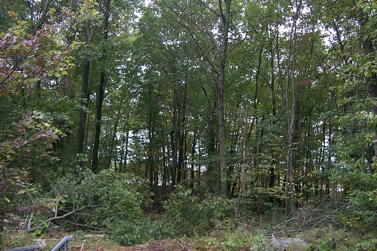
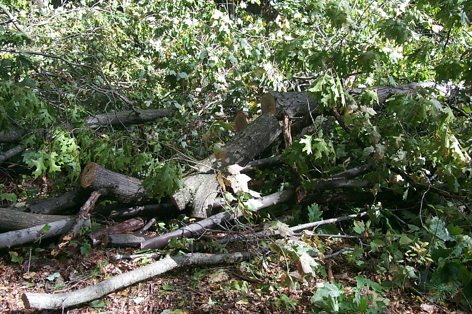
Before we could start reassembling the tower and mounting all the new antennas additional trees needed to be cut down to clear a path in the woods to crank the tower back up.
Weeks of bad weather, and waiting for the trees to be cleared, have been delaying the tower project and I was starting to worry that we might not get the repeater tower back up before the snow starts falling. Then finally late this afternoon Jeff and his crew showed up and in just a few short hours were able to cut down all remaining tress that were still interfering with the towers path.


(click on images to enlarge)
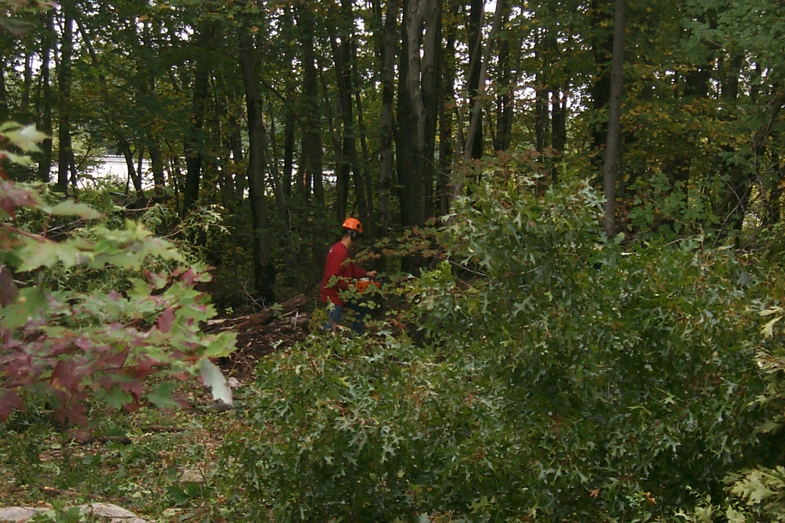
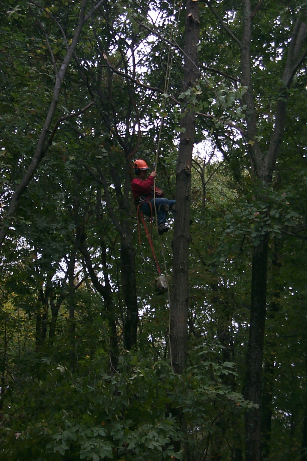
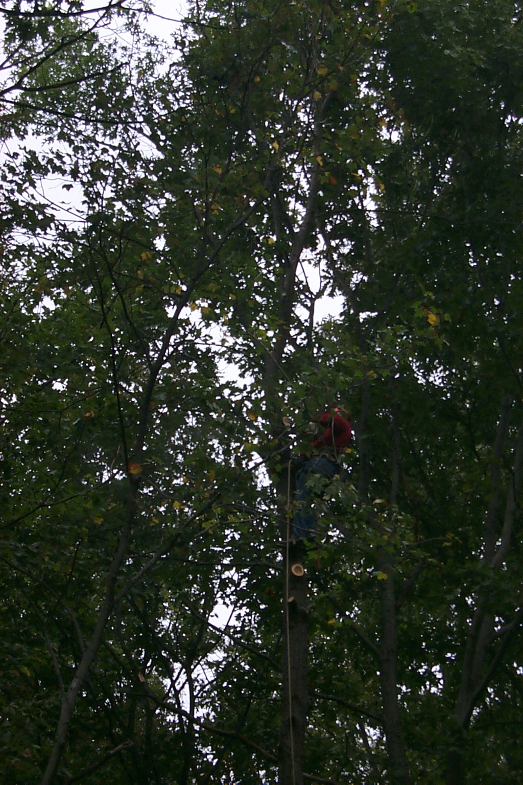
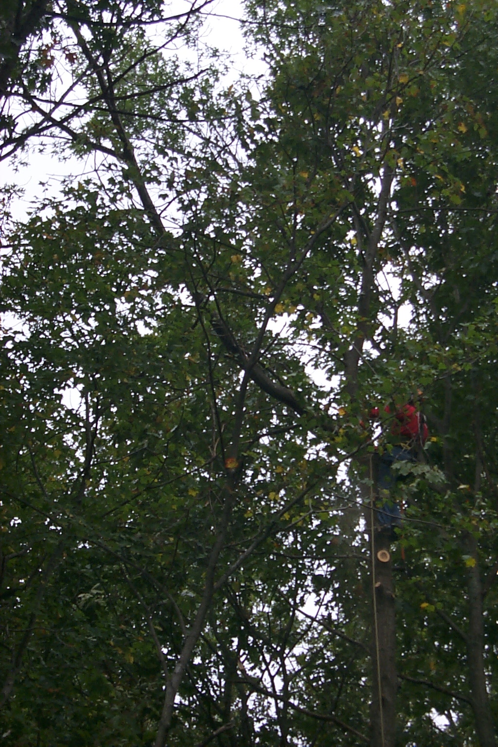
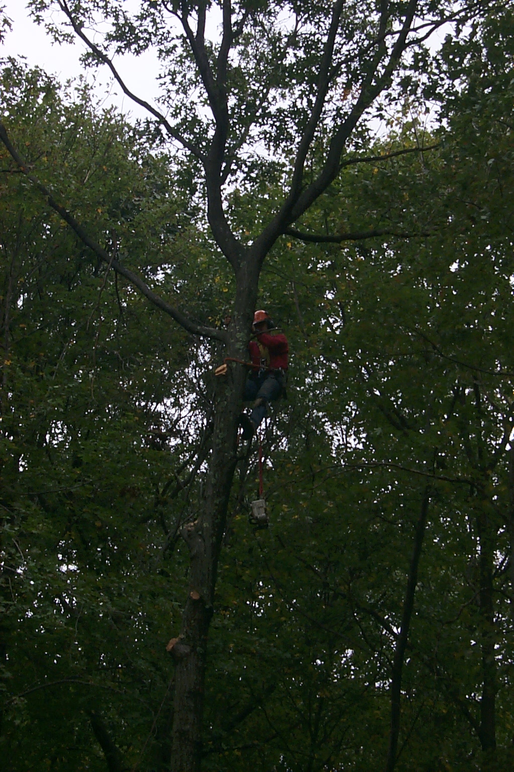
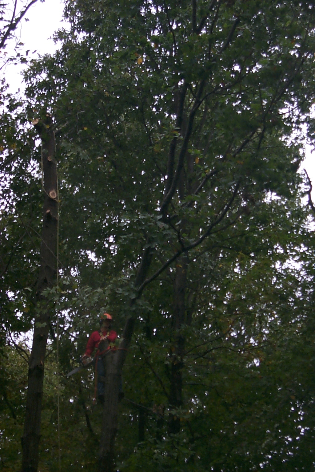
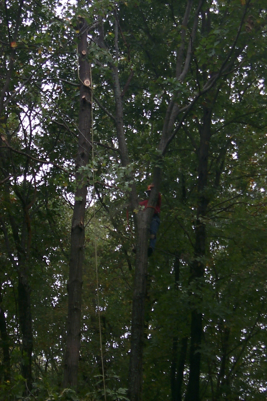
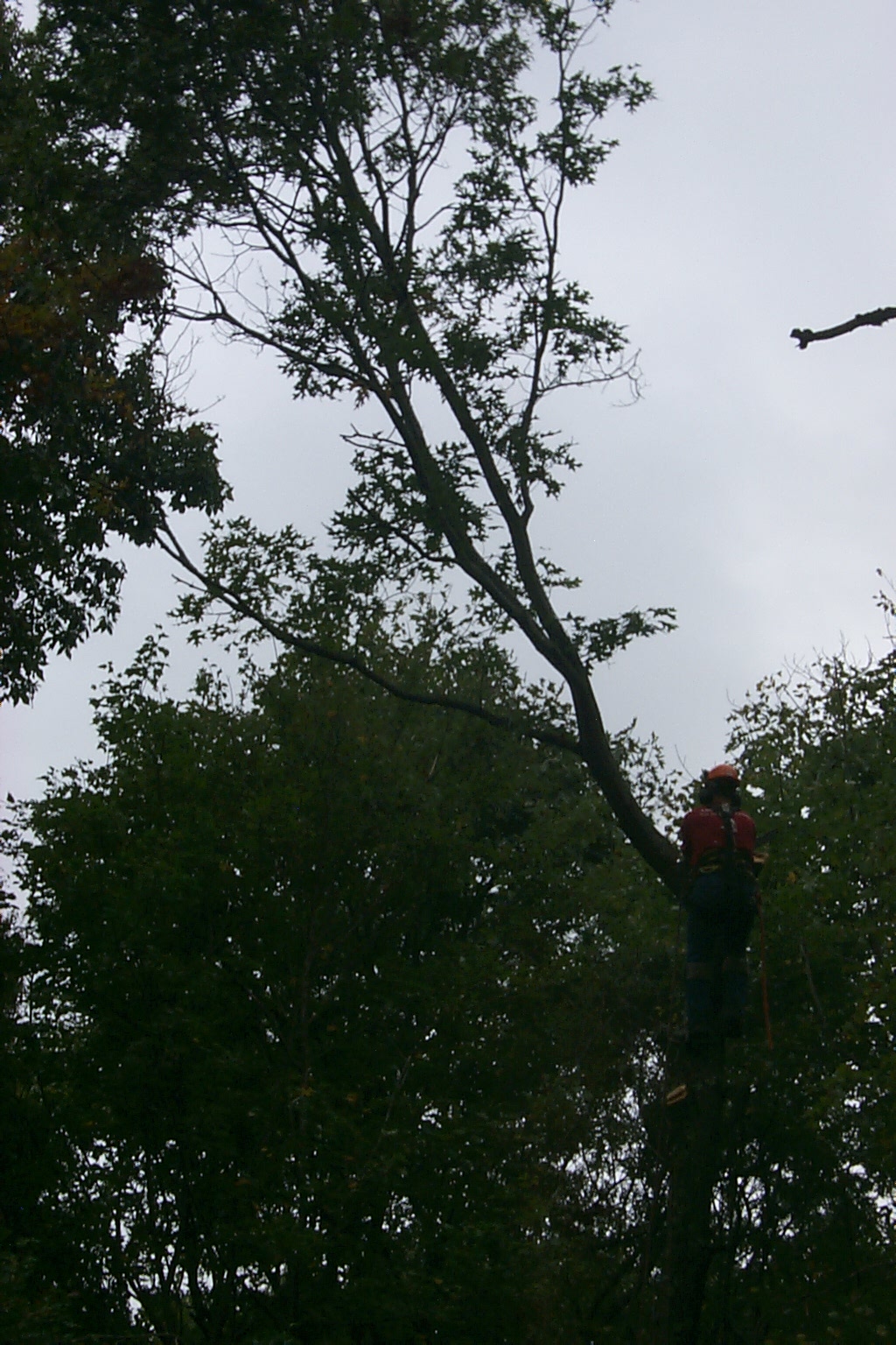
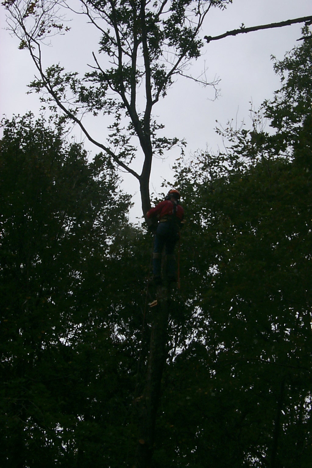
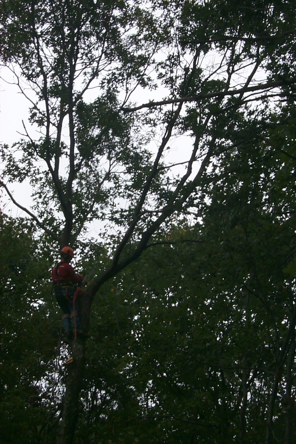
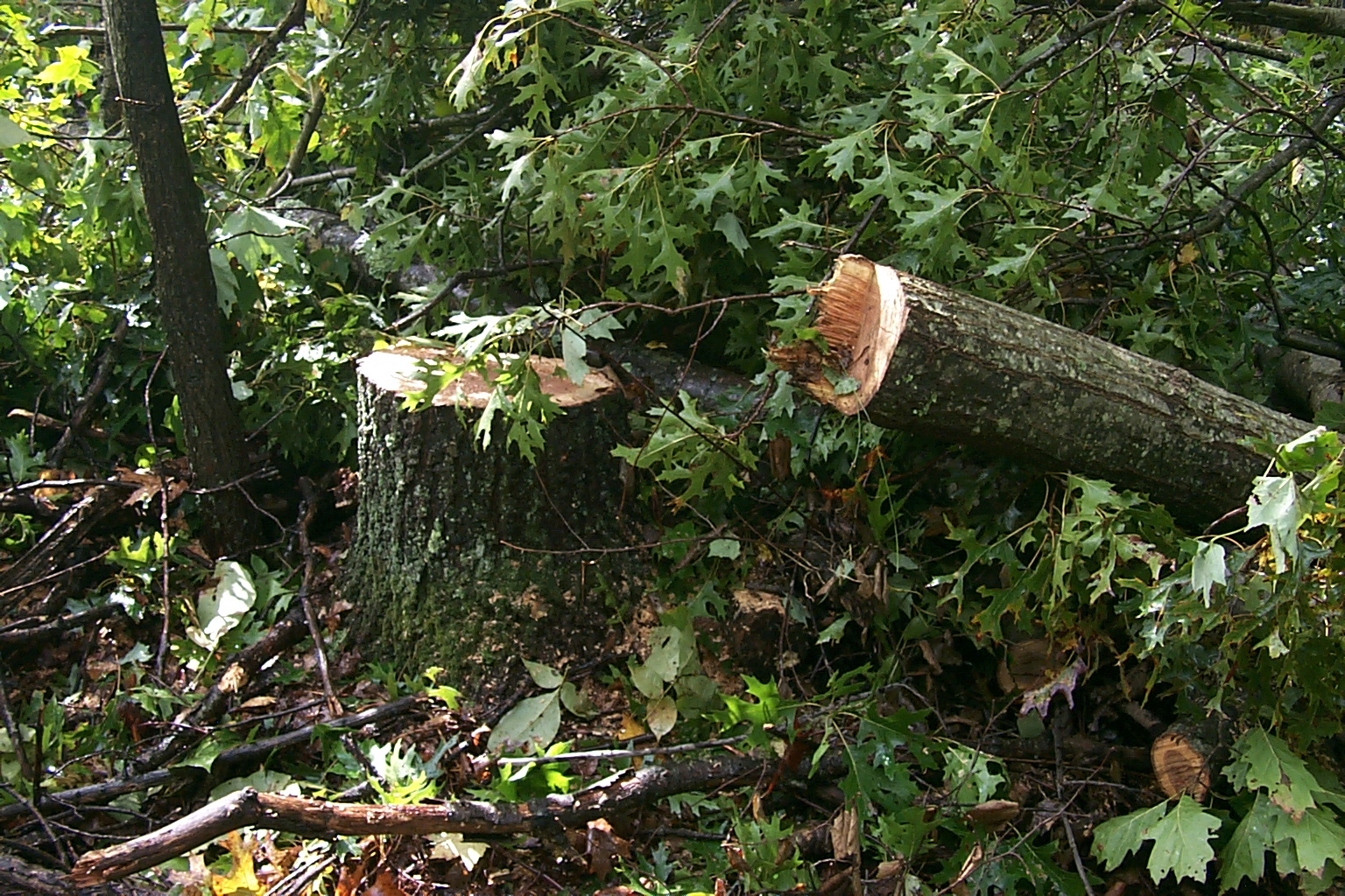
Jeff was fearless, climbing over 75 feet into the tops of the trees, swinging from his safety harness, as he pruned off all the tops branches one at a time... He dropped them down to the ground with the precision of a surgeon, until there was nothing but the trunks of the tree left standing.


(click on images to enlarge)
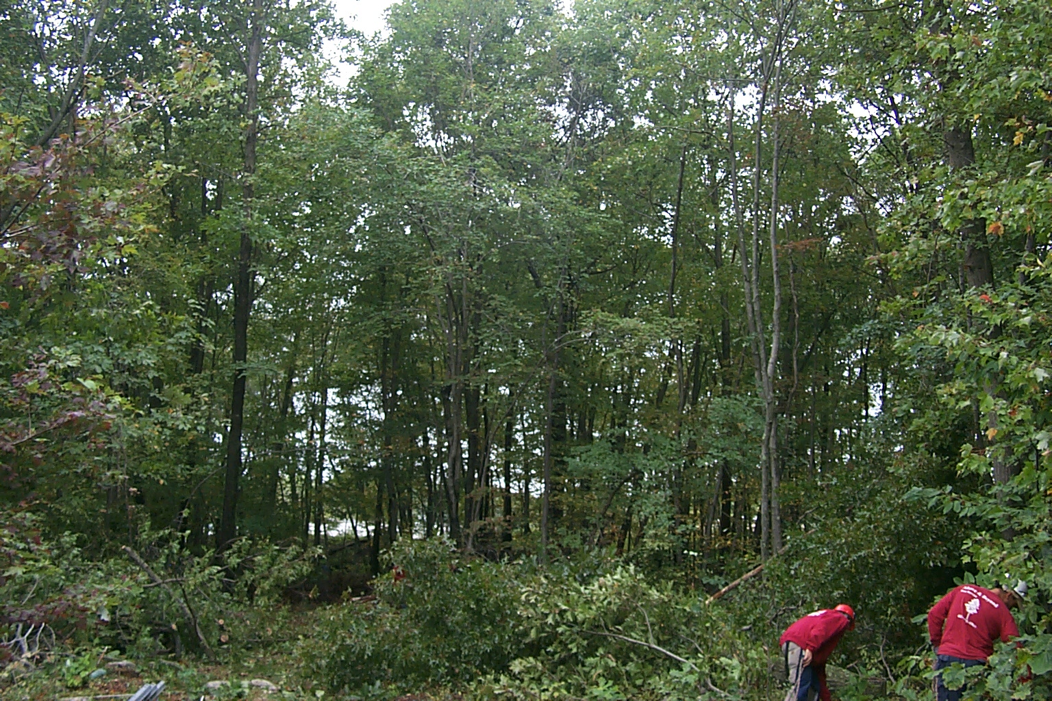
Slowly, branch by branch, tree by tree, the heavy dark foliage was replaced by daylight and views of the sky...


(click on images to enlarge)
Monday Afternoon October 8th
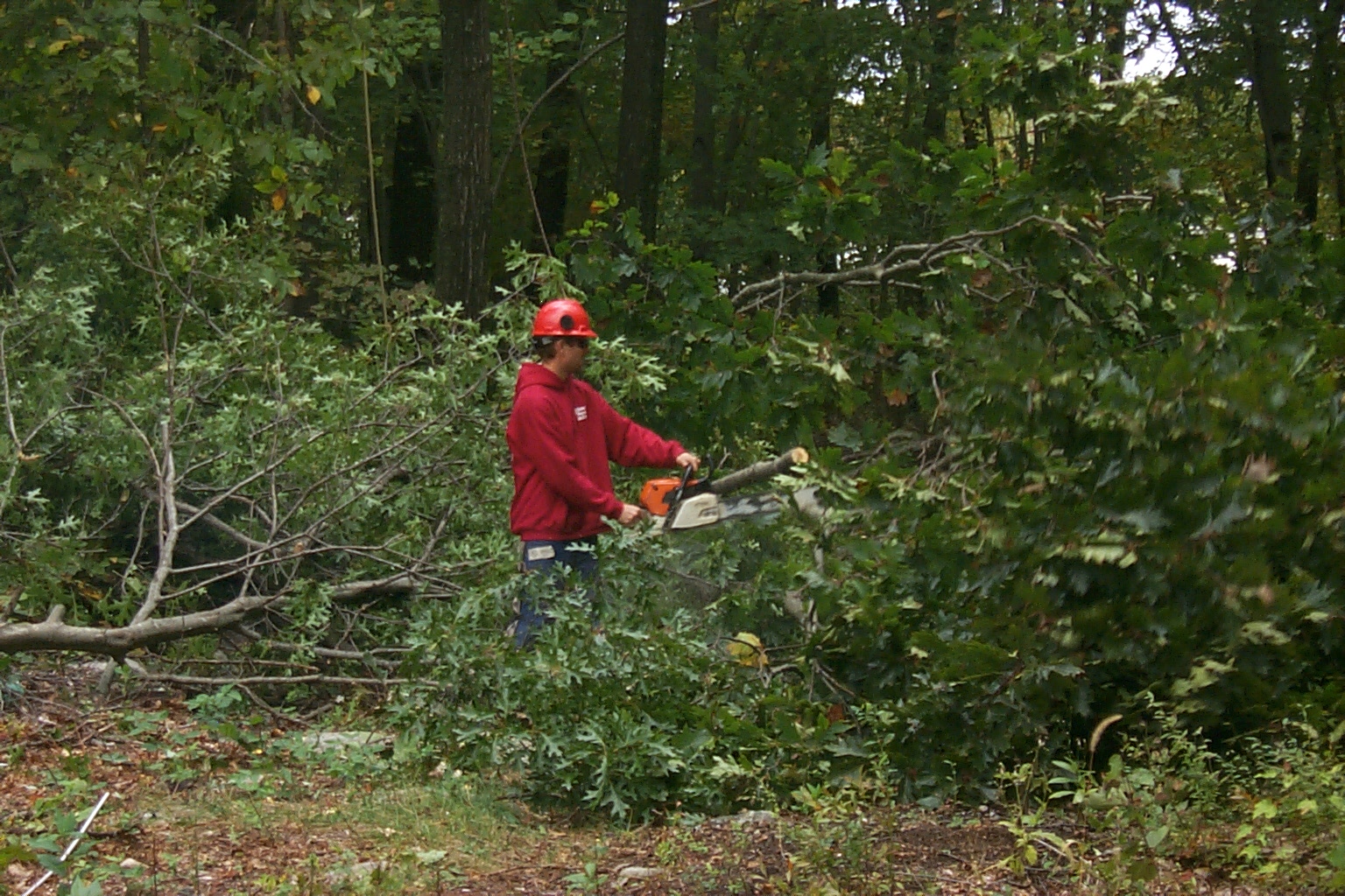
The weather was beautiful today and even thought I ended up working a few hours it was my first day of vacation. Dad and I got an early start this morning cutting up all of the large limbs and branches from all the trees had been cut down last week.
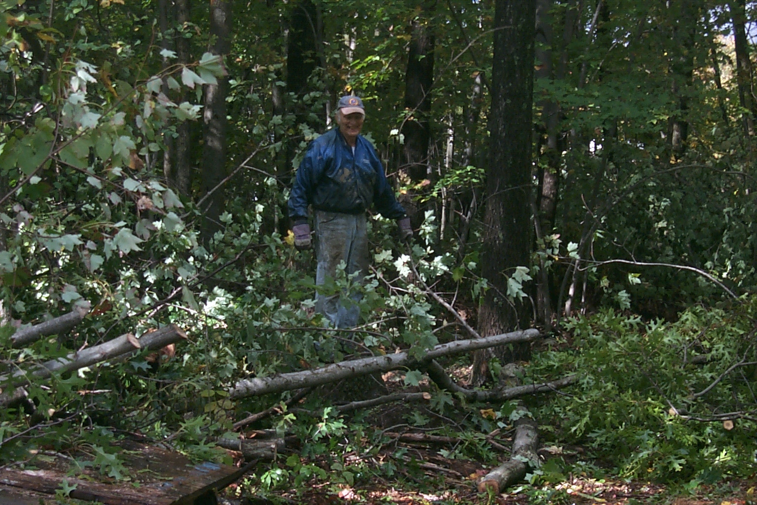


(click on images to enlarge)
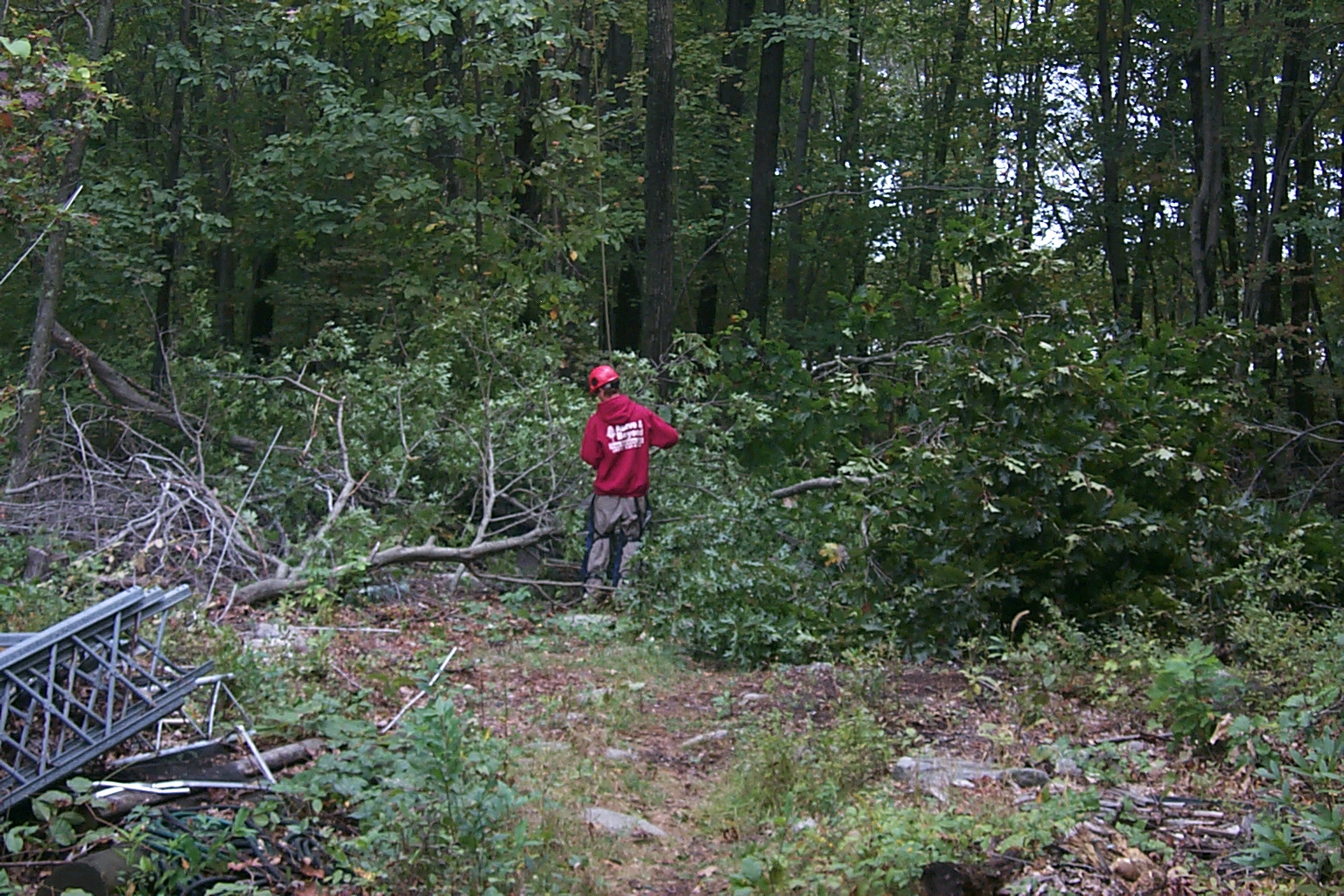
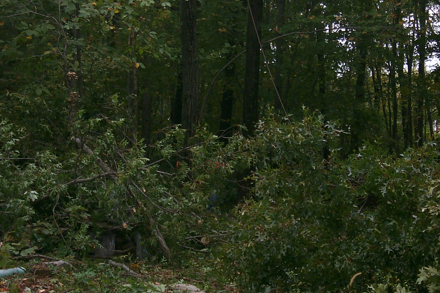
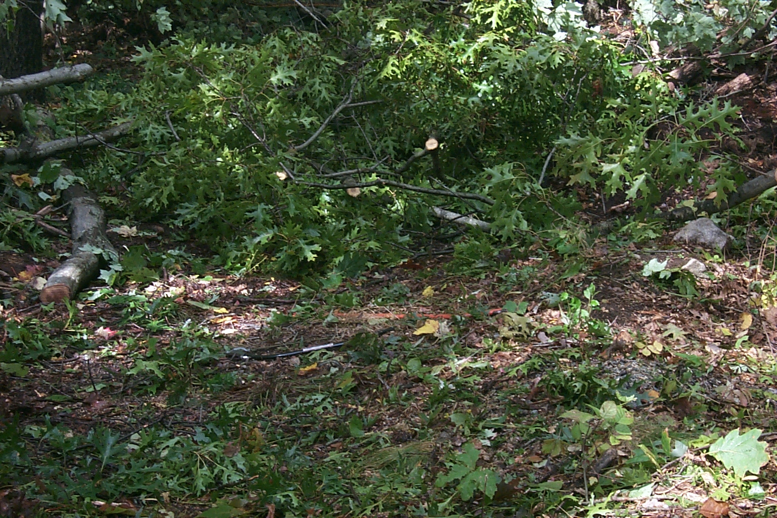
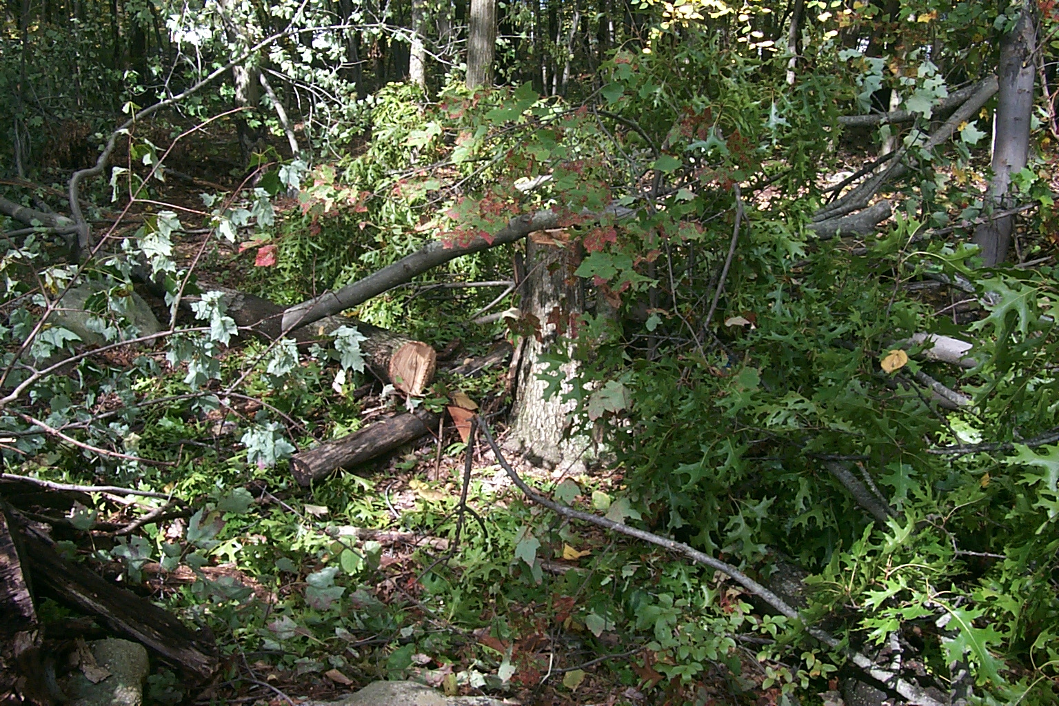
When we were done with the larger limbs and branches Dad continued clearing a few additional small trees, bushes, and ground cover clearing the area where we would be reassembling the tower and install all the new antennas.


(click on images to enlarge)
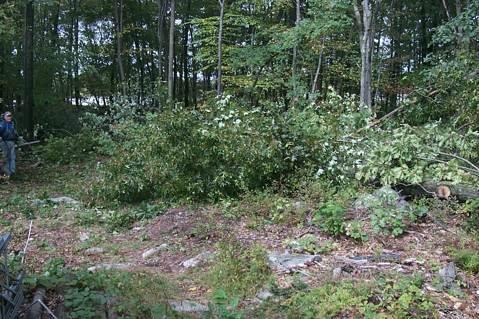
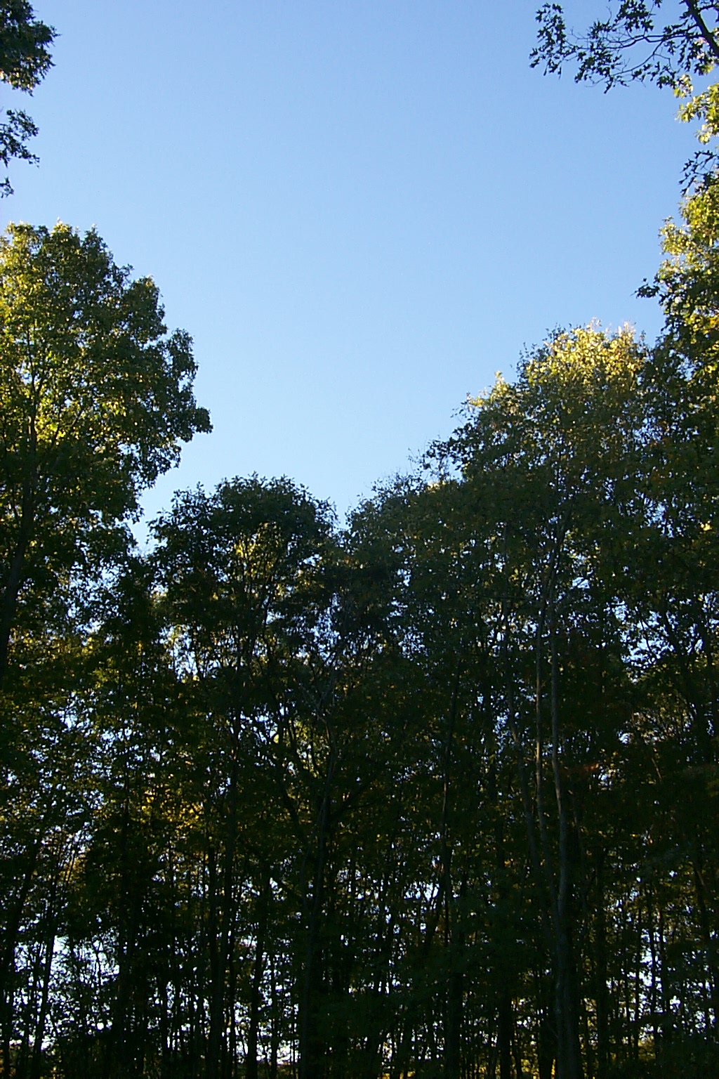
There is a lot of wide open, blue sky now were just last week there was nothing but a wall of trees!

(click on images to enlarge)
Sunday Morning October 10th
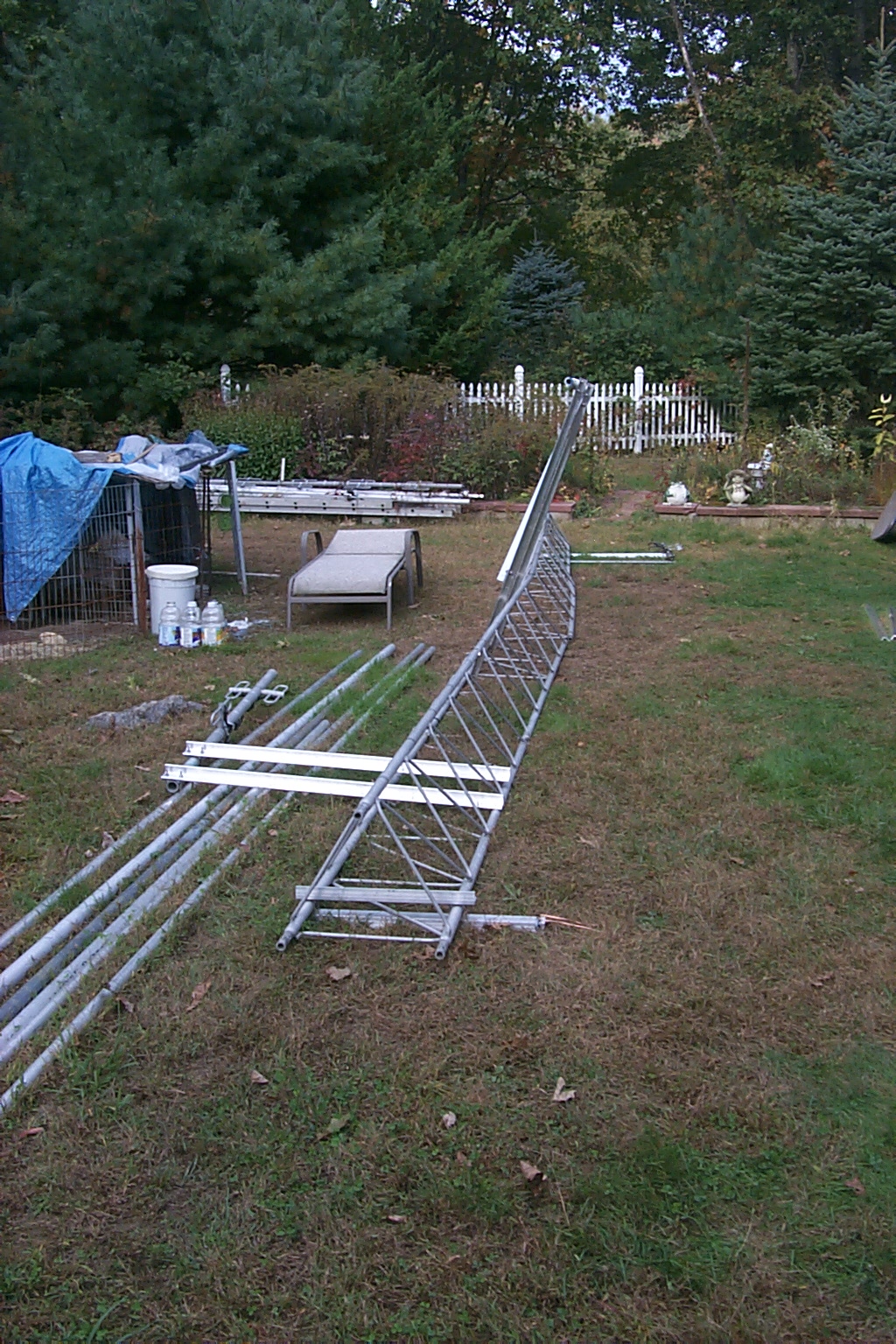
!!! The tower is going back together !!!
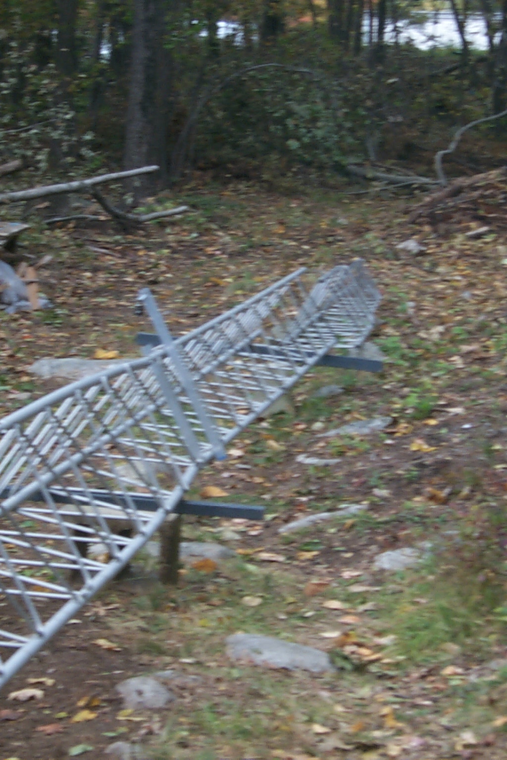
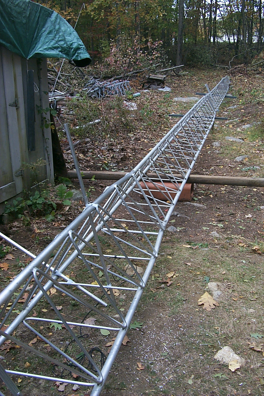
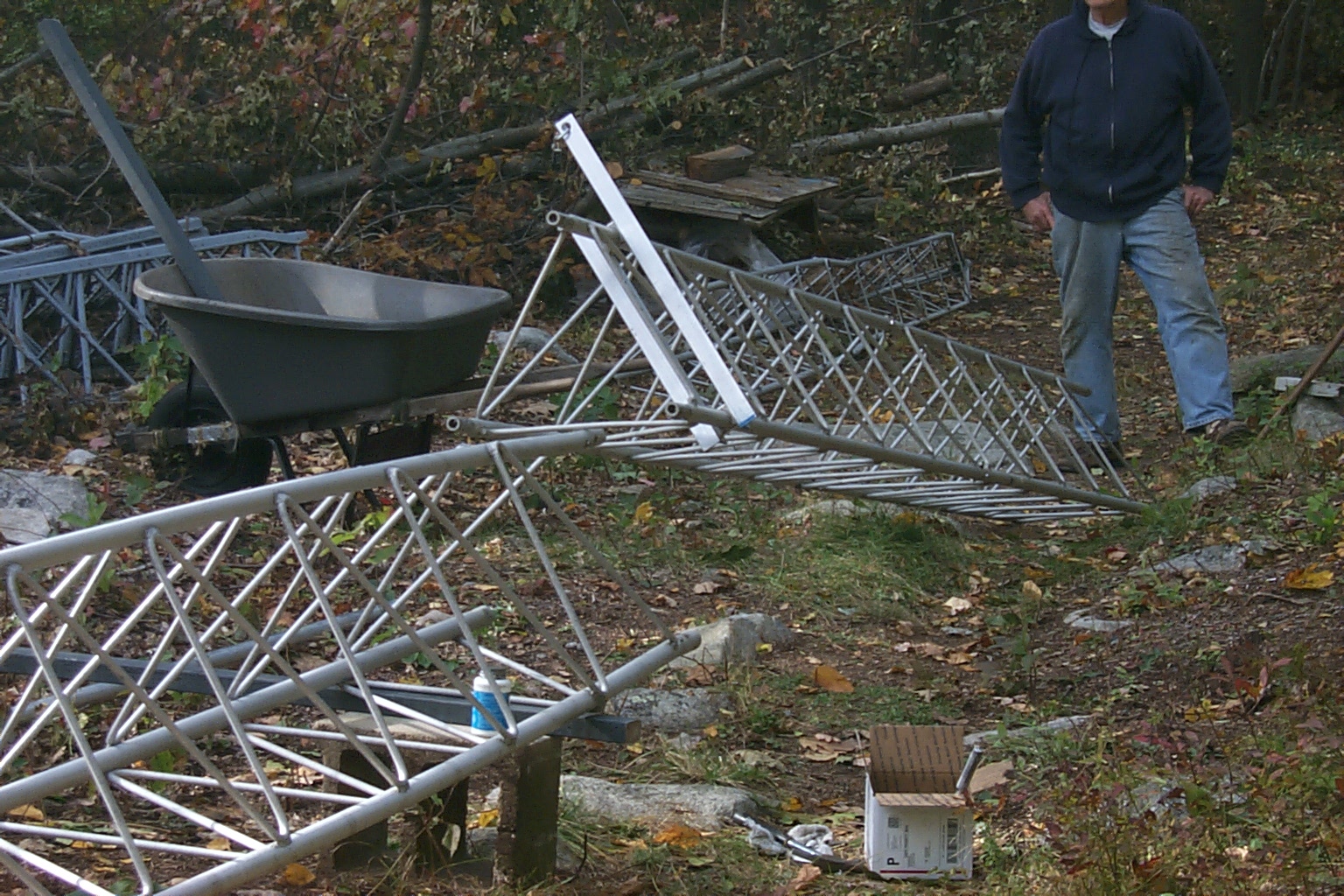
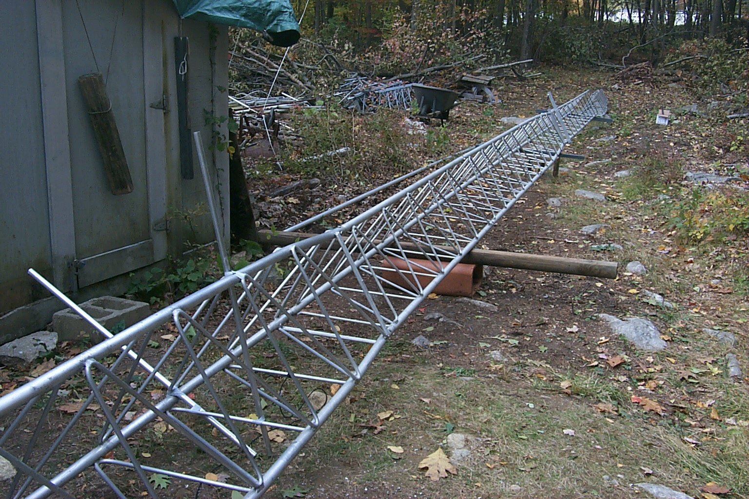
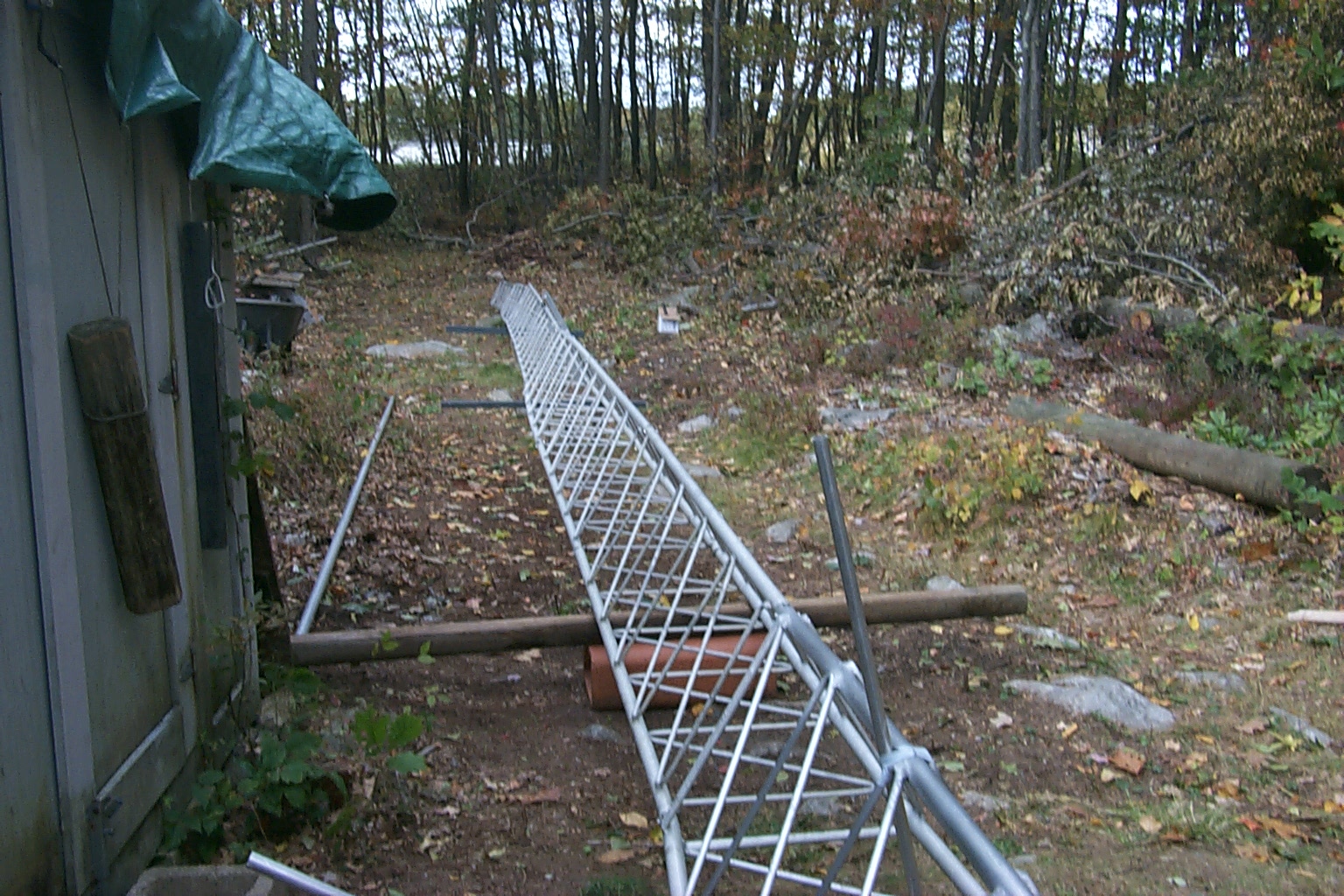
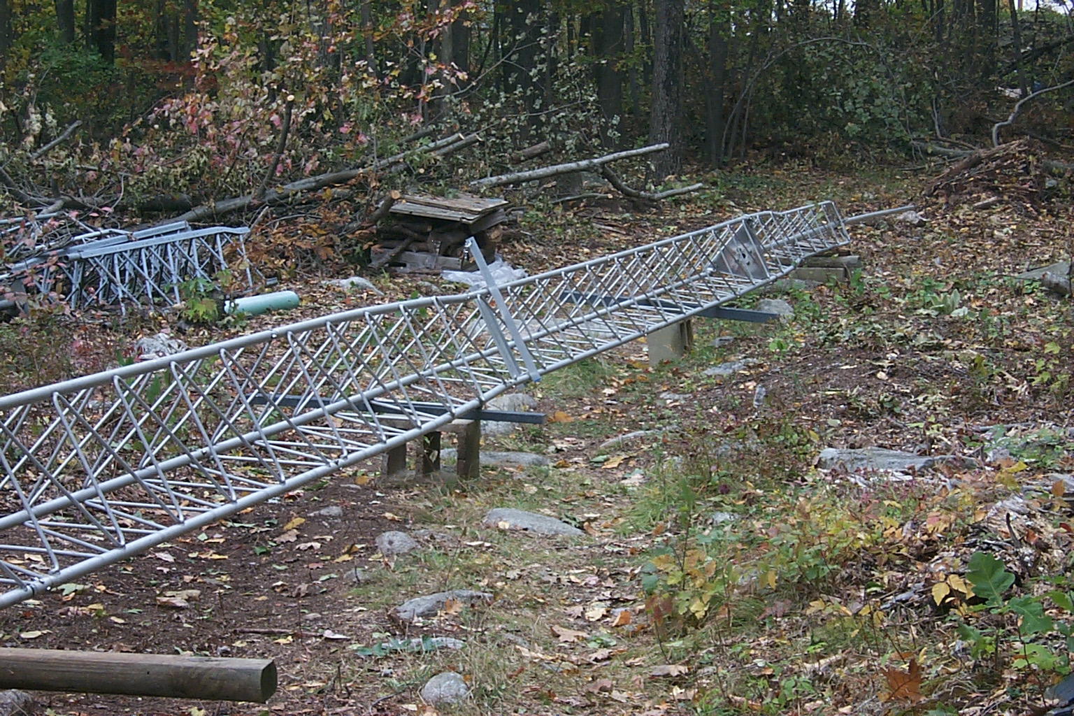
Today Dad and I started putting the tower back together... Once again the weather was beautiful and the temperature was perfect for all the heavy work lugging the tower sections back up to the tower location in the woods.
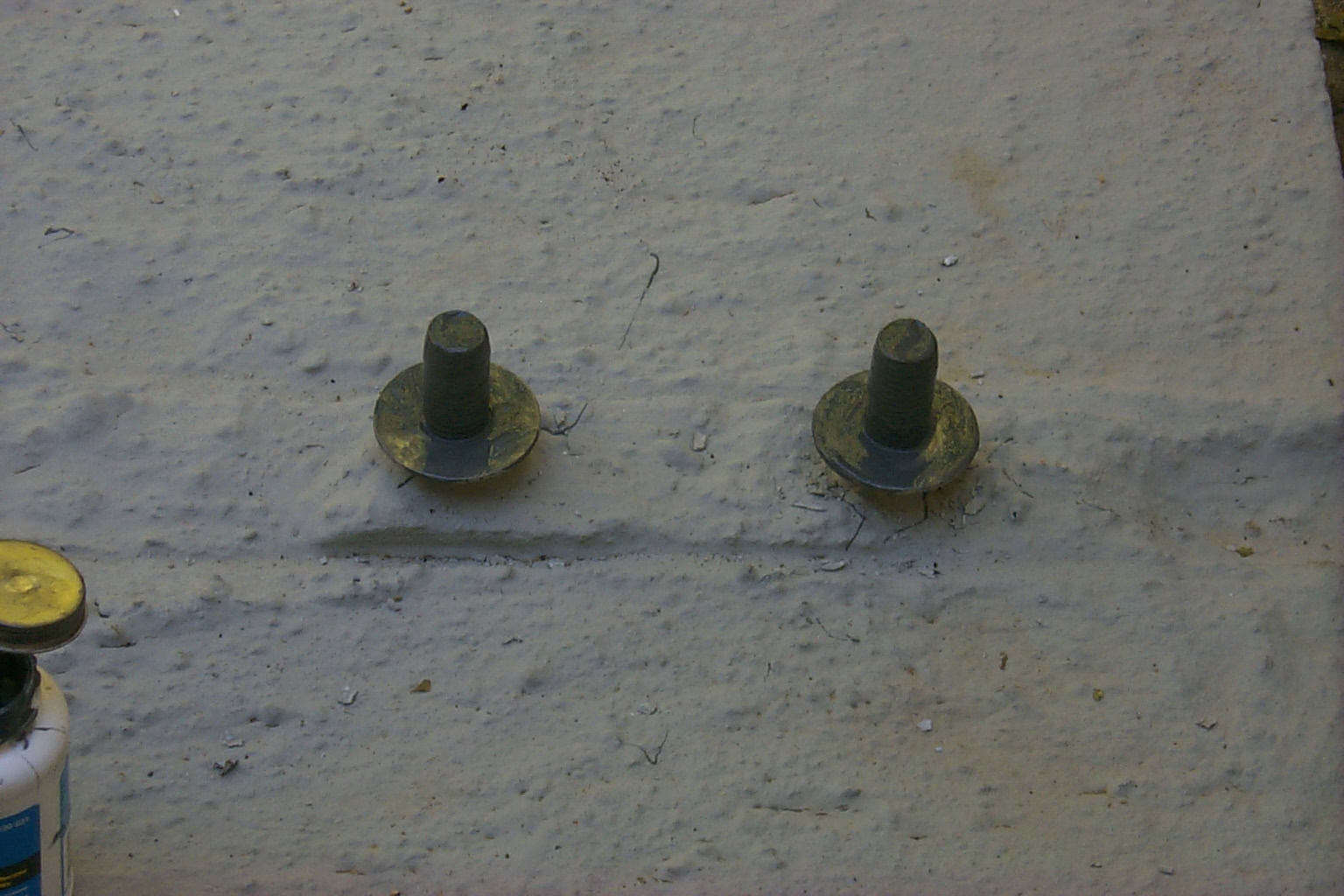
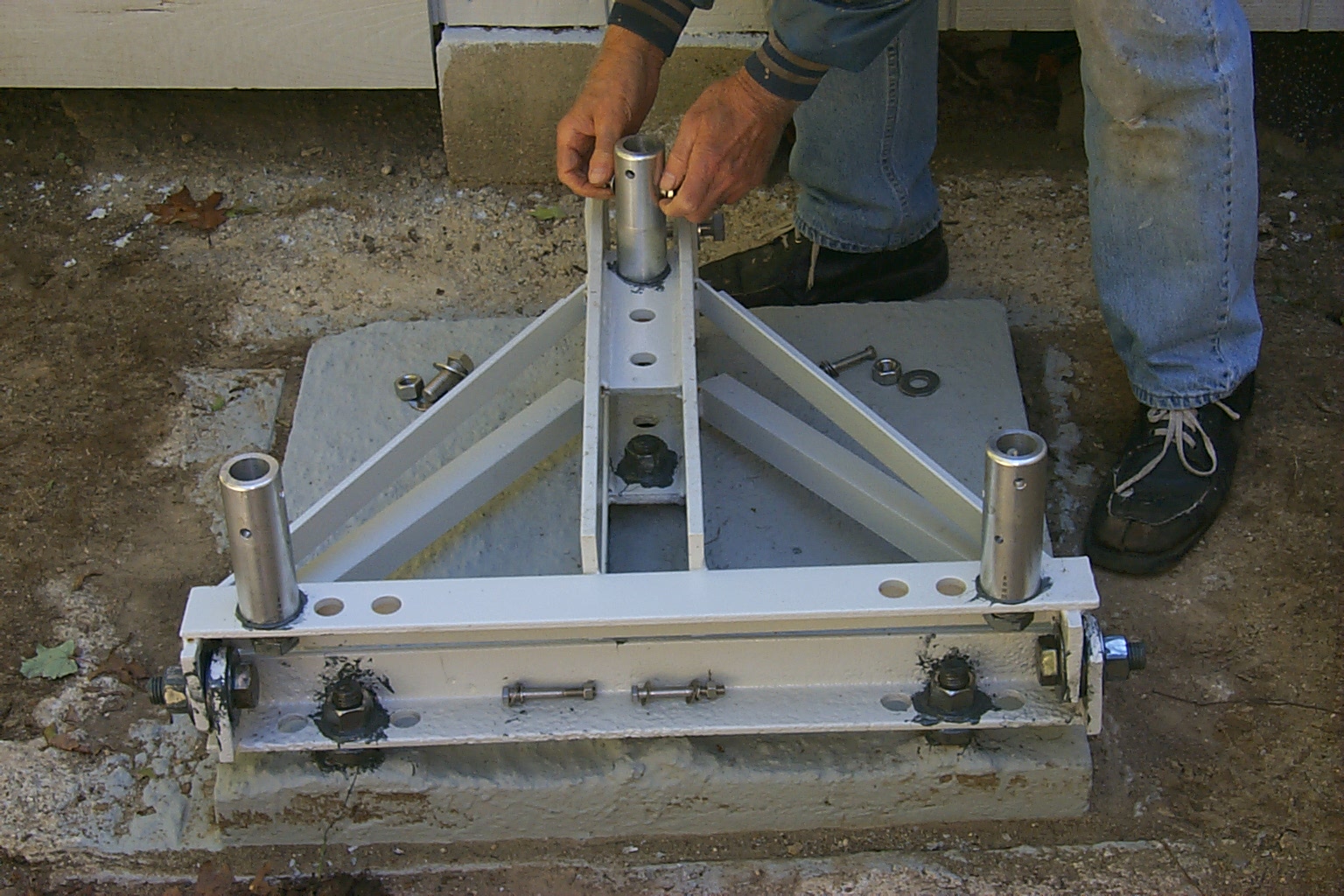
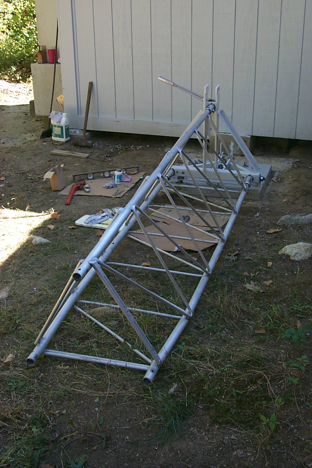
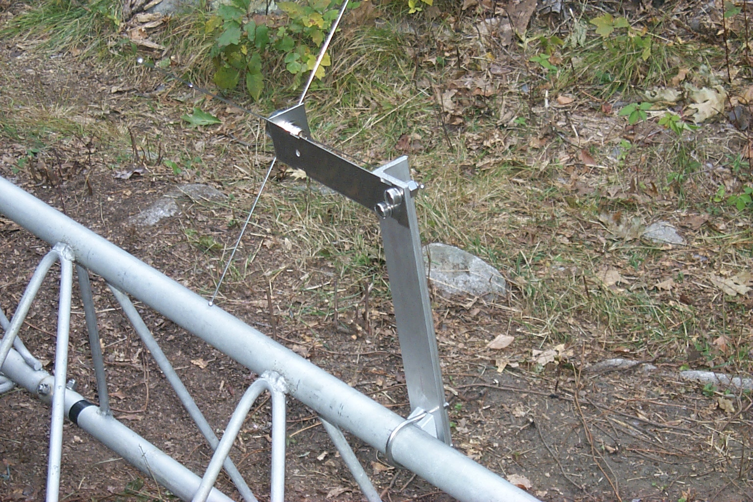
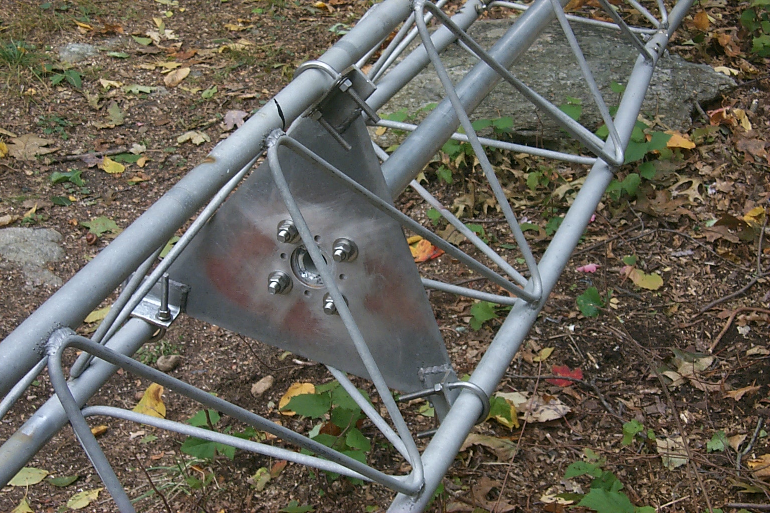
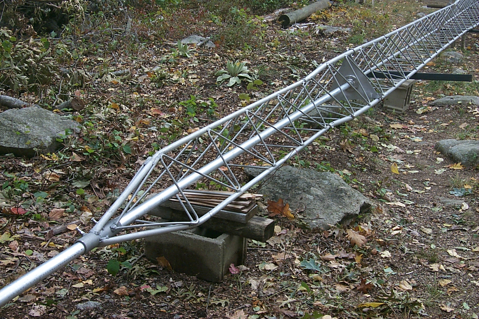
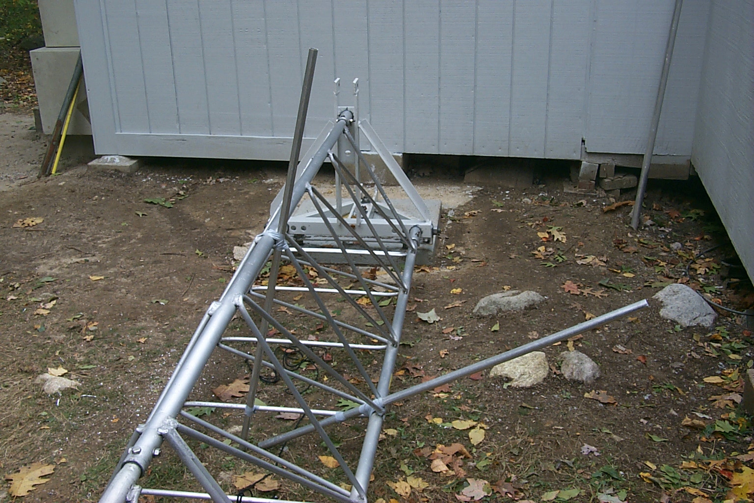
We started bolting the bottom section of the hinged base to the concrete base. I replaced all the old hardware (nuts & washers) from 1993 with new stainless steel hardware and everything received a liberal coating of anti-oxidization goop.


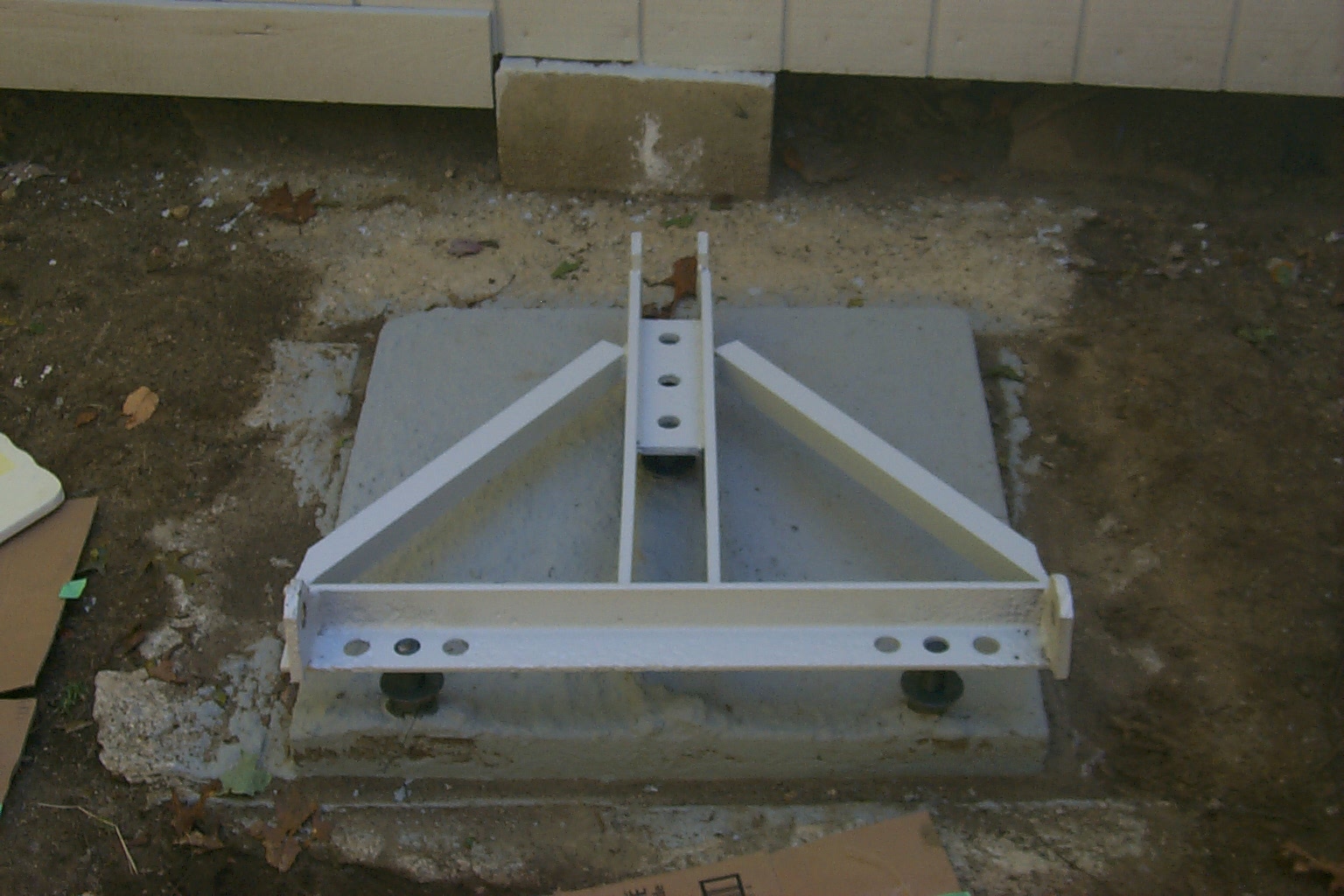

(click on images to enlarge)
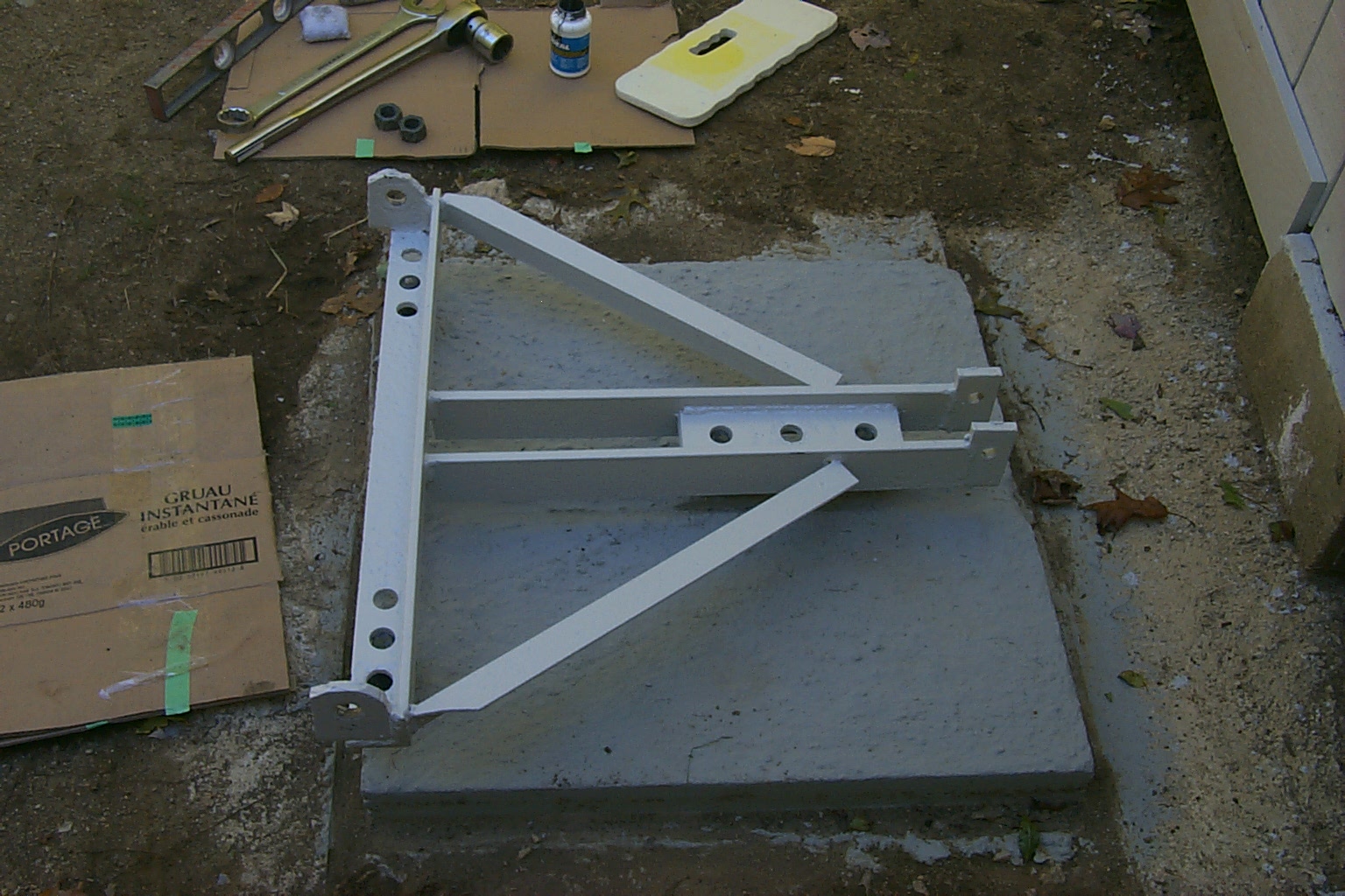
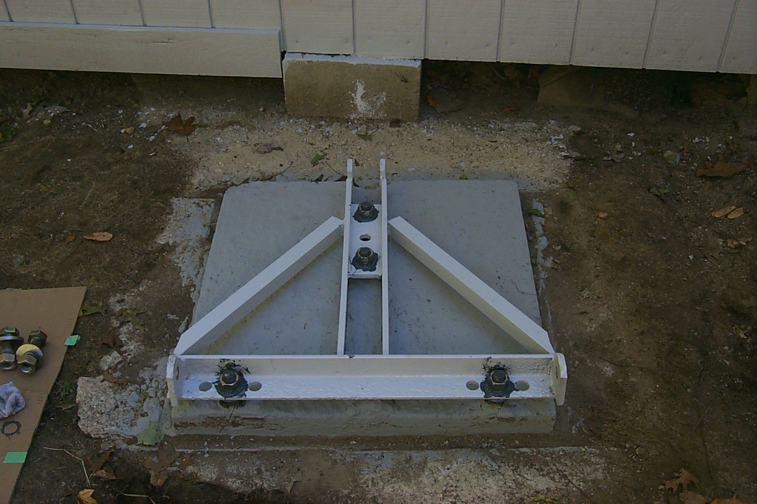
Once the bottom section of the hinged base was in place we checked for level and bolted on the top section of the hinged base. More goop applied to all the hardware as it was assembled...


(click on images to enlarge)
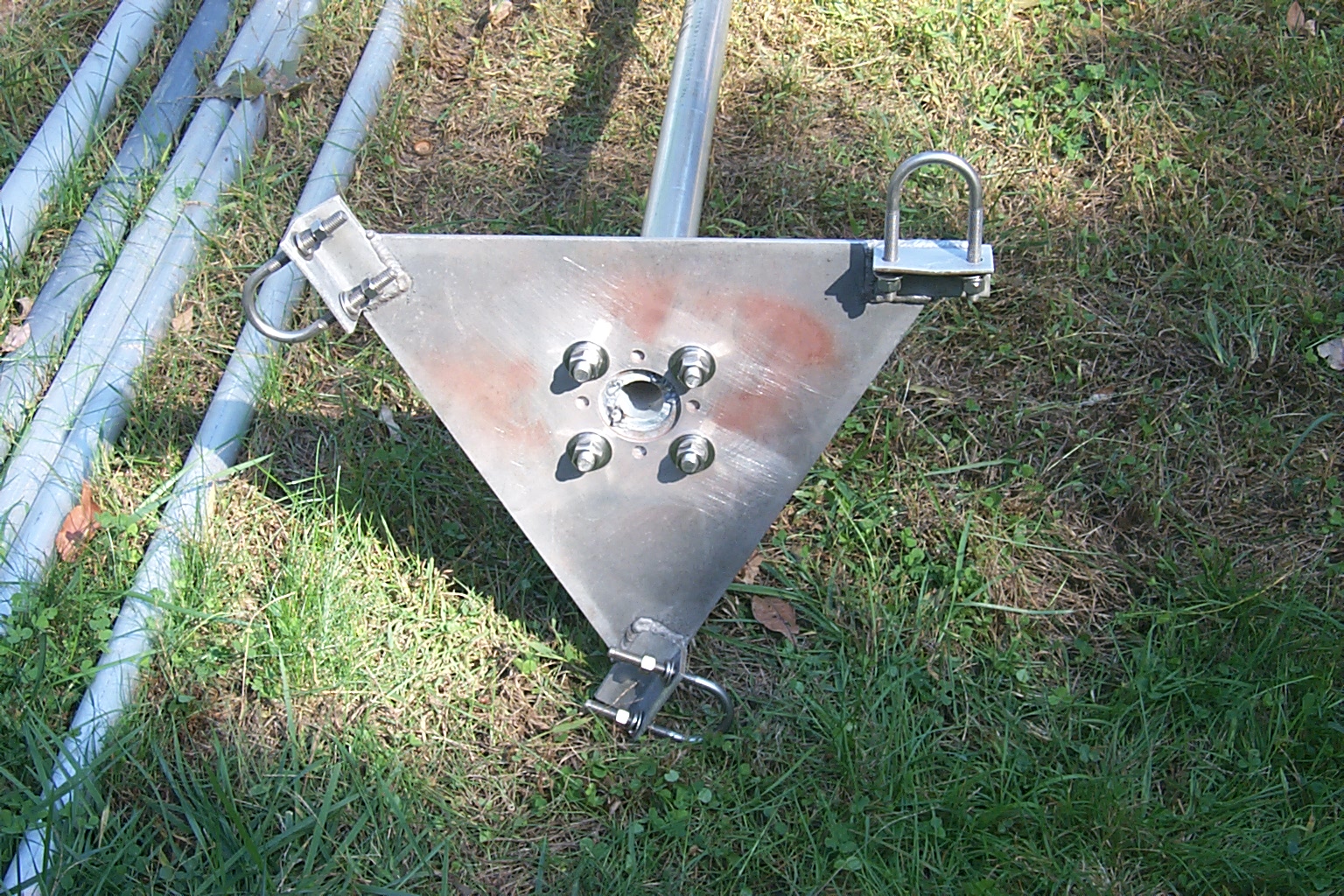
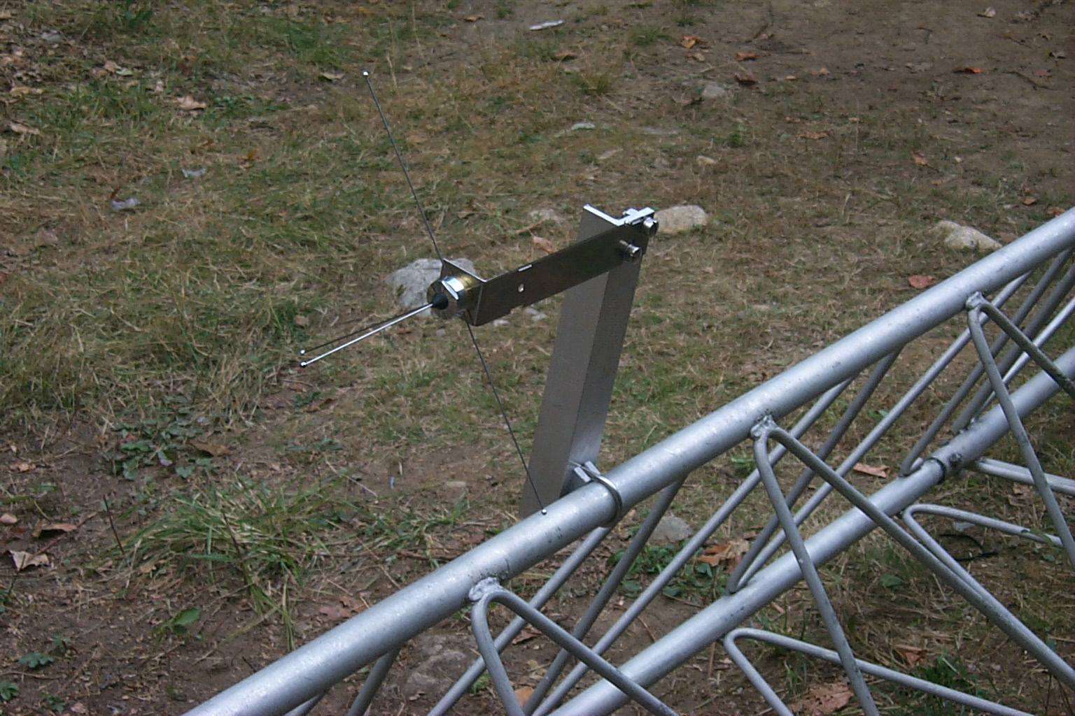
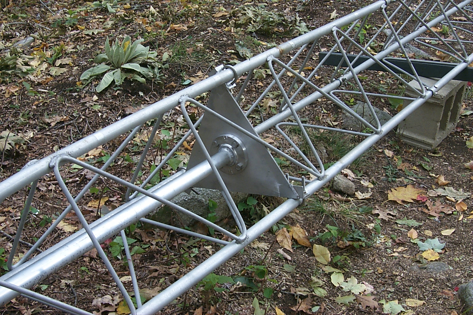
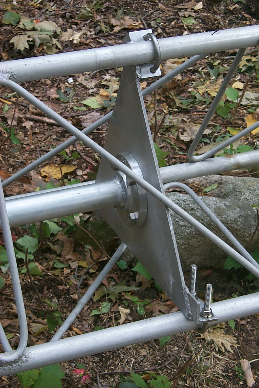
After making some adjustments to get the hinged base section level on the concert base I bolted everything done tight and we loosely installed the three new mounting stubs to receive the bottom section of tower...
... More goop on everything.
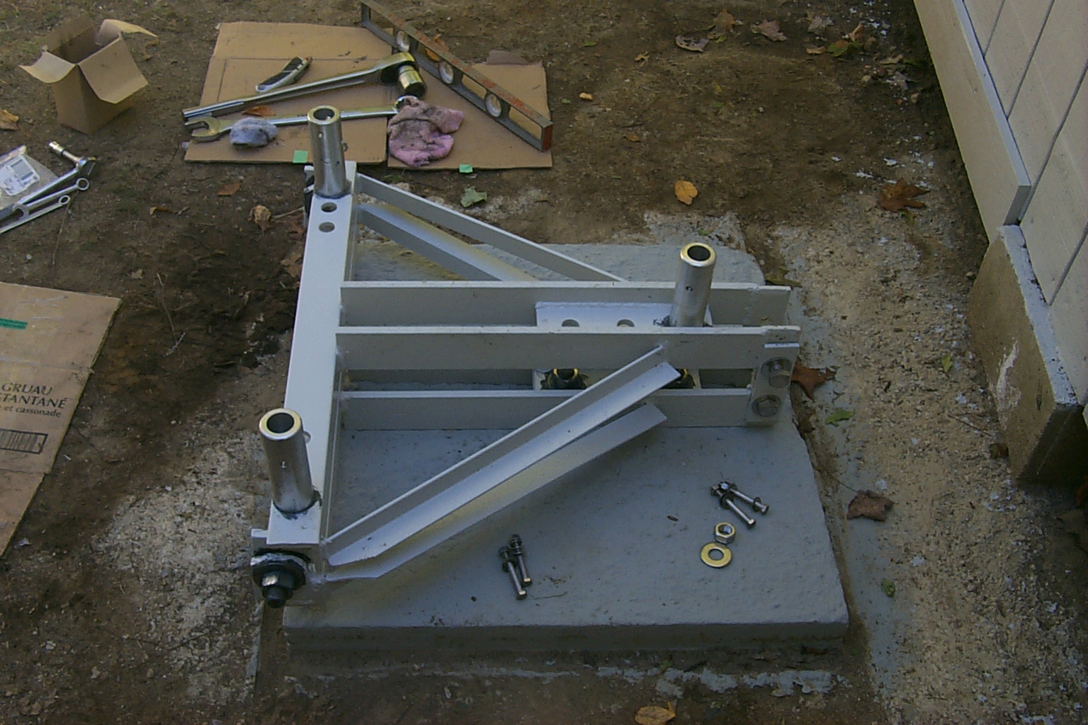

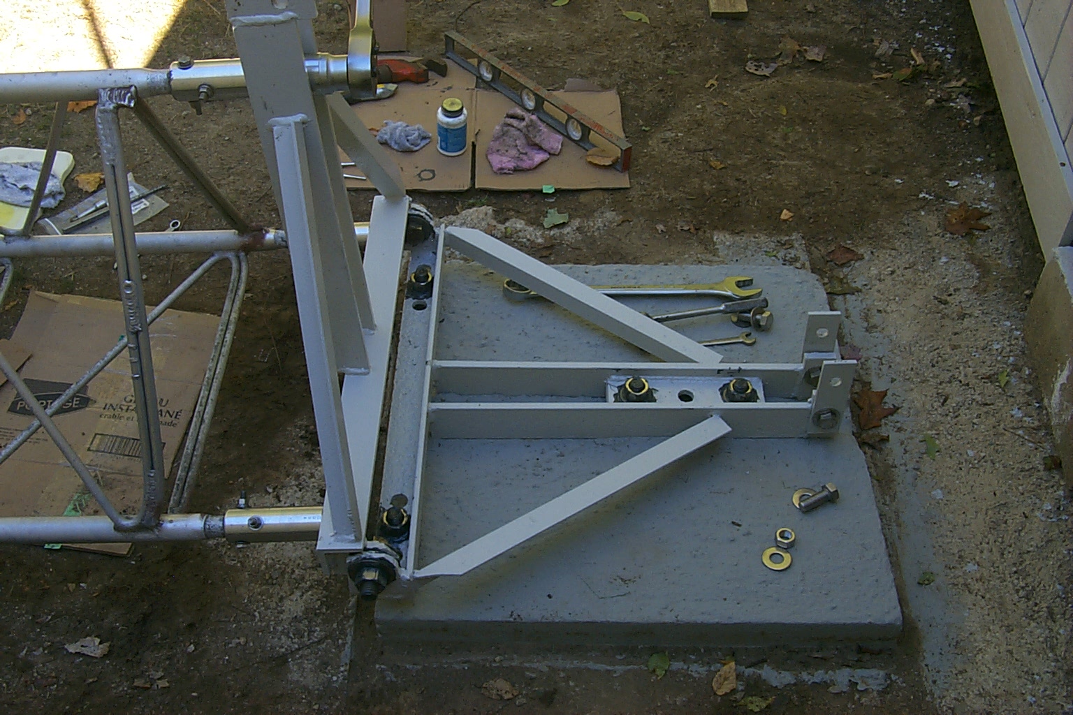
(click on images to enlarge)
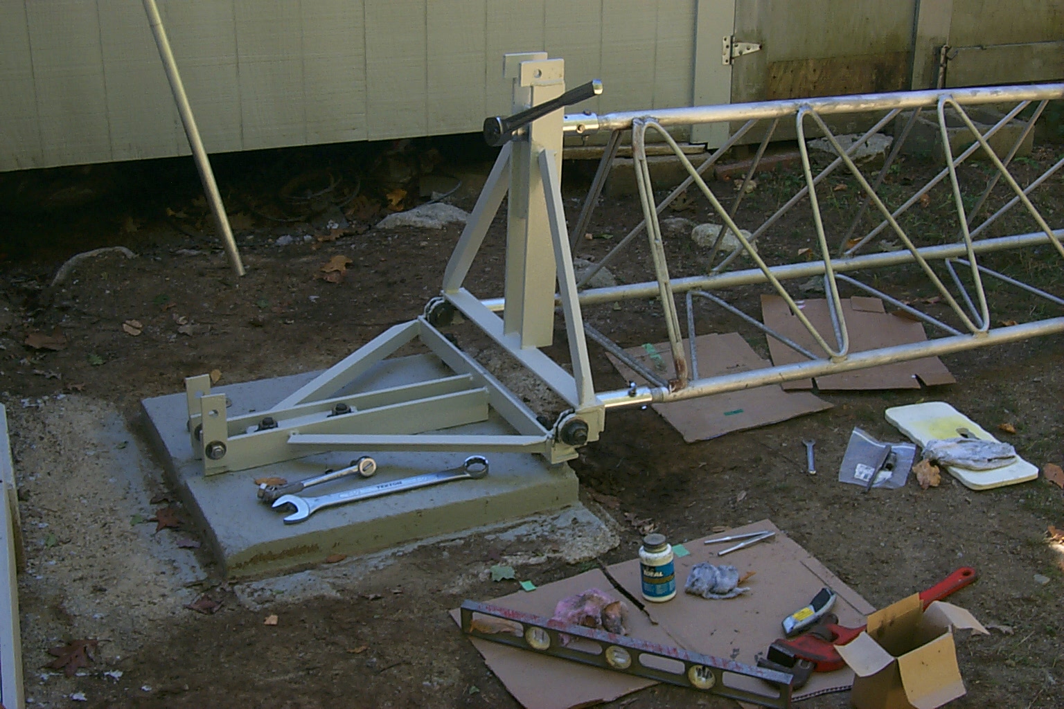
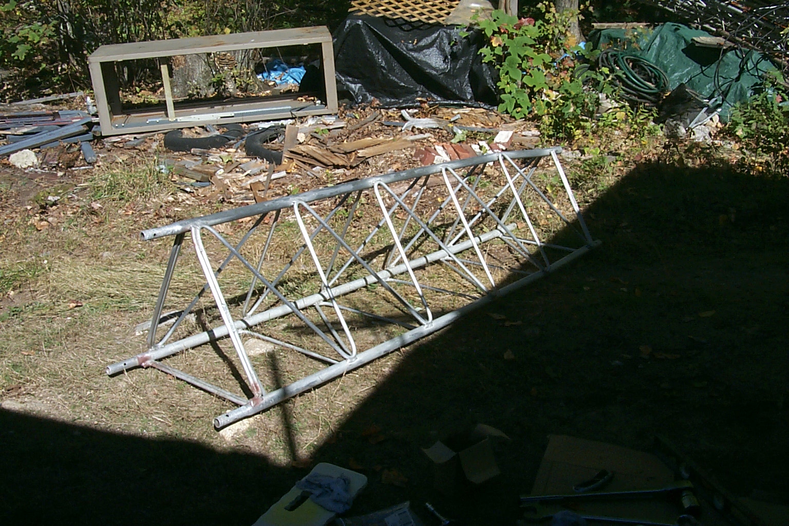
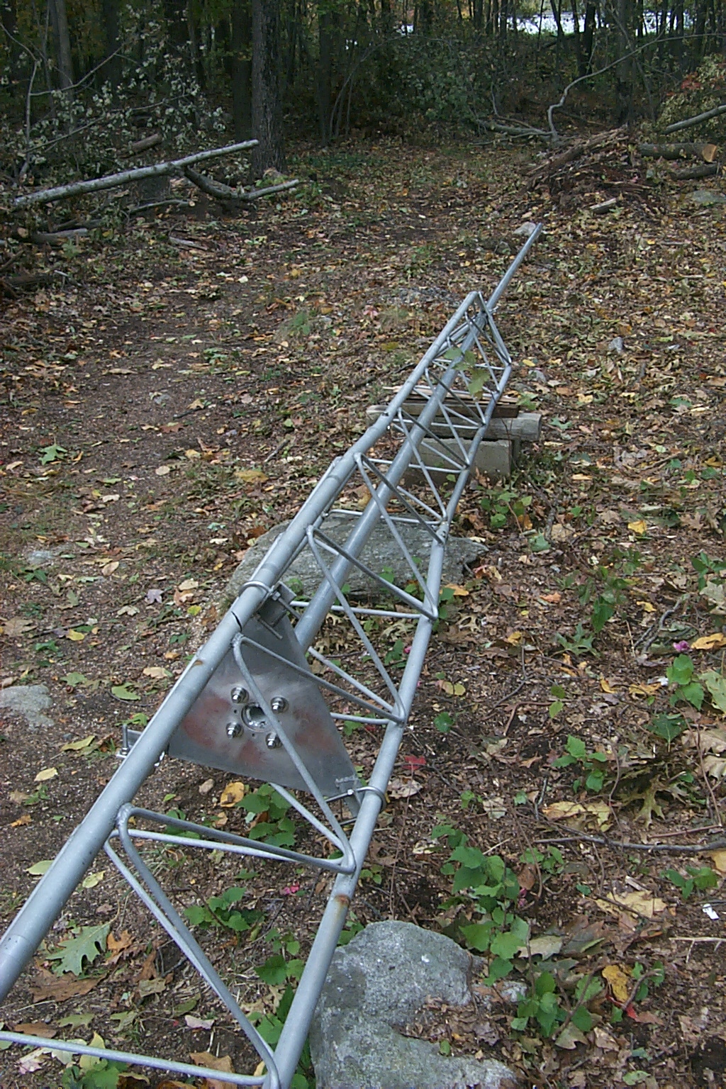
With the bottom section of tower bolted onto the hinged base we were able to grab the next three sections of tower and bolt that onto the base section.
(click on images to enlarge)

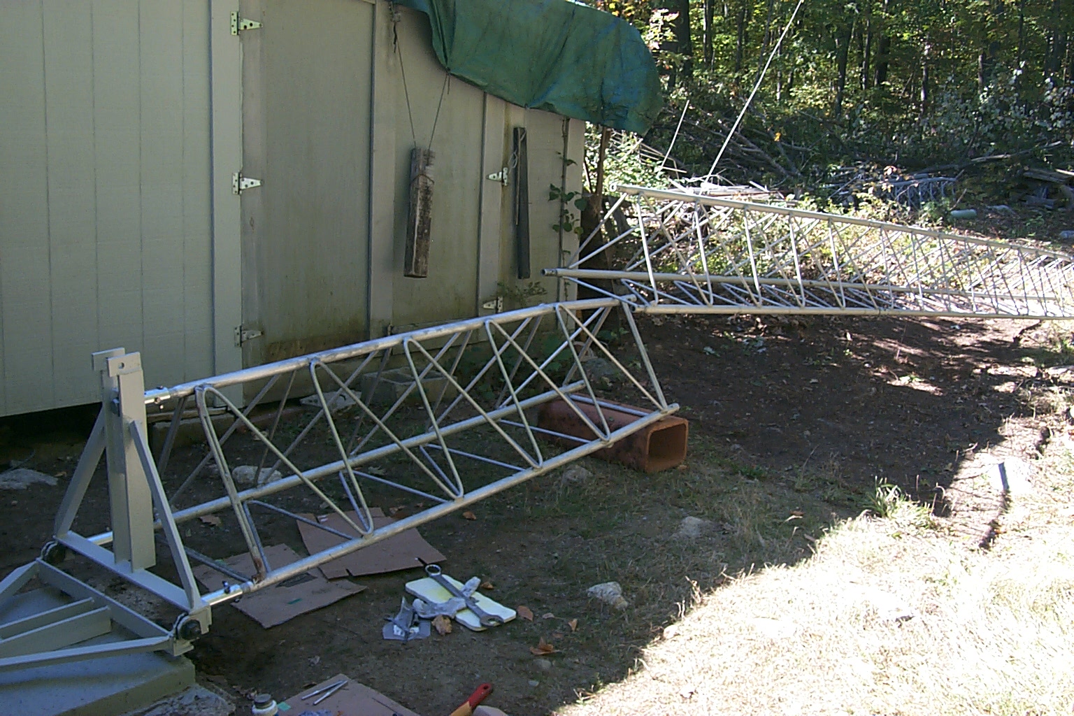

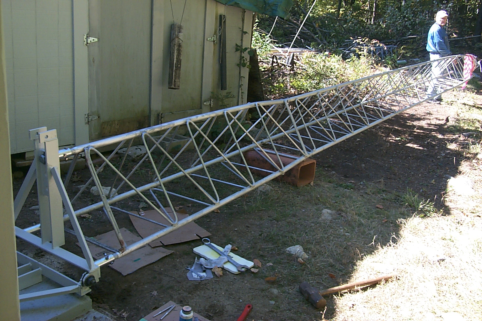
(click on images to enlarge)
Oh yea... Today is also my wedding anniversary so at this point we stopped working on the tower so I could take Sandy out for dinner.
Tomorrow I hope to get started by mounting my new JAG 144-148 "Thunder Boomer" on the tower, cranking up the four sections we have assembled and performing the fine tuning adjustments for the best VSWR. Jag is on "stand-bye" waiting for Dad and I to call if we have any issues getting the new end mounted Yagi dialed in on my tower.
Monday Morning October 11th
Tuning the JAG 144-148 "Thunder Boomer"
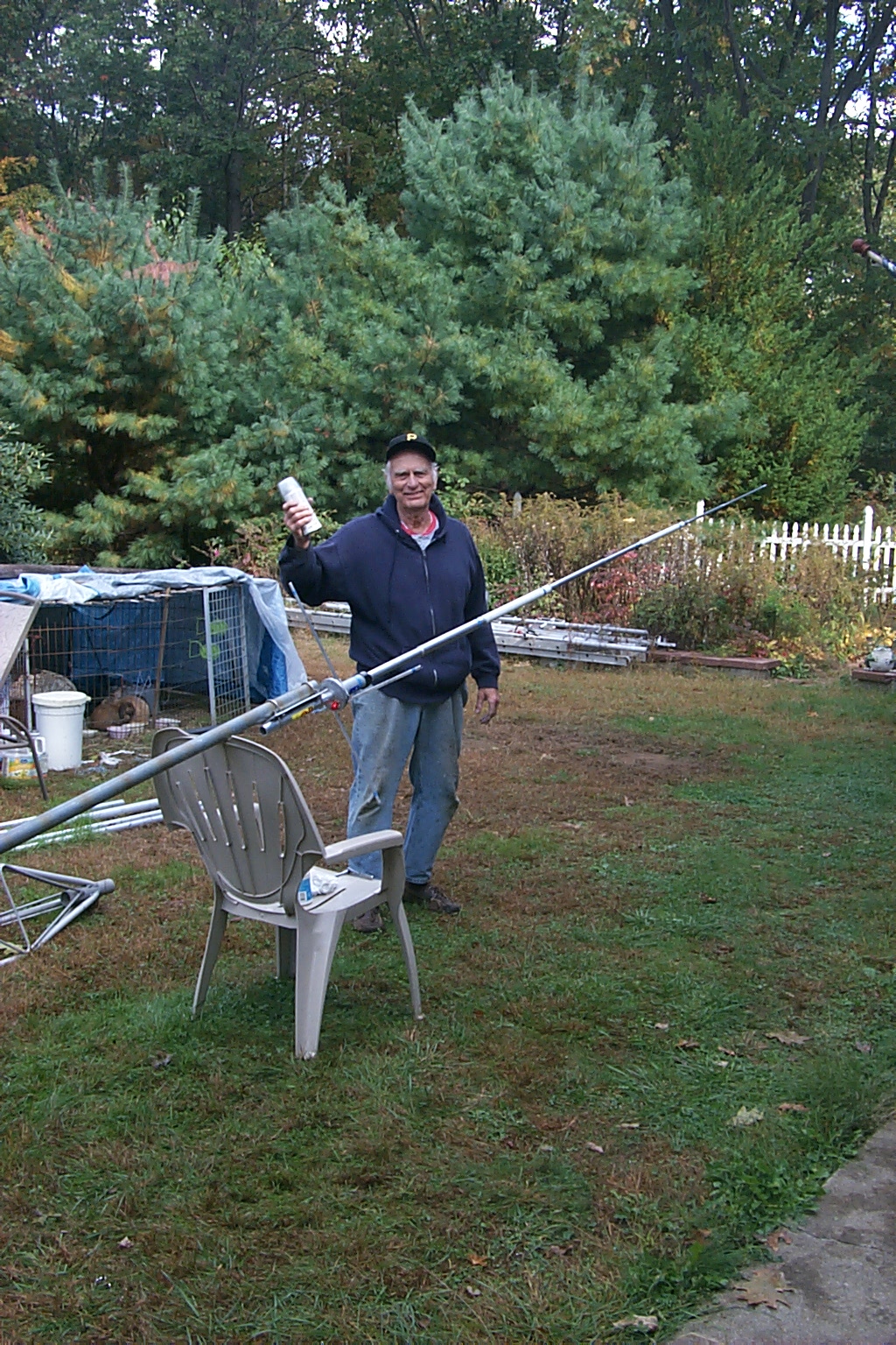
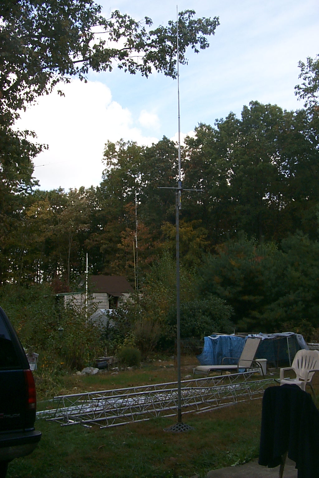
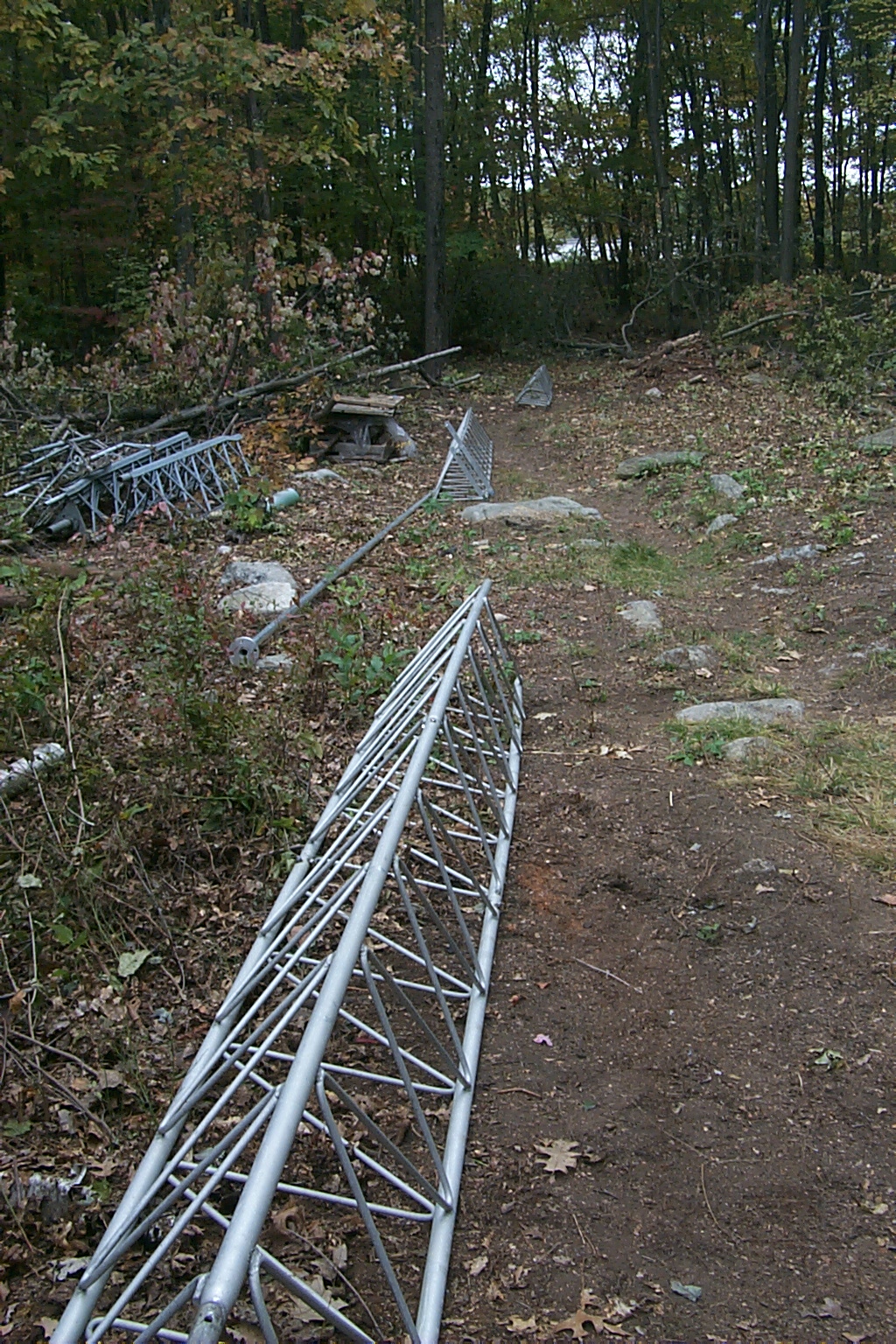
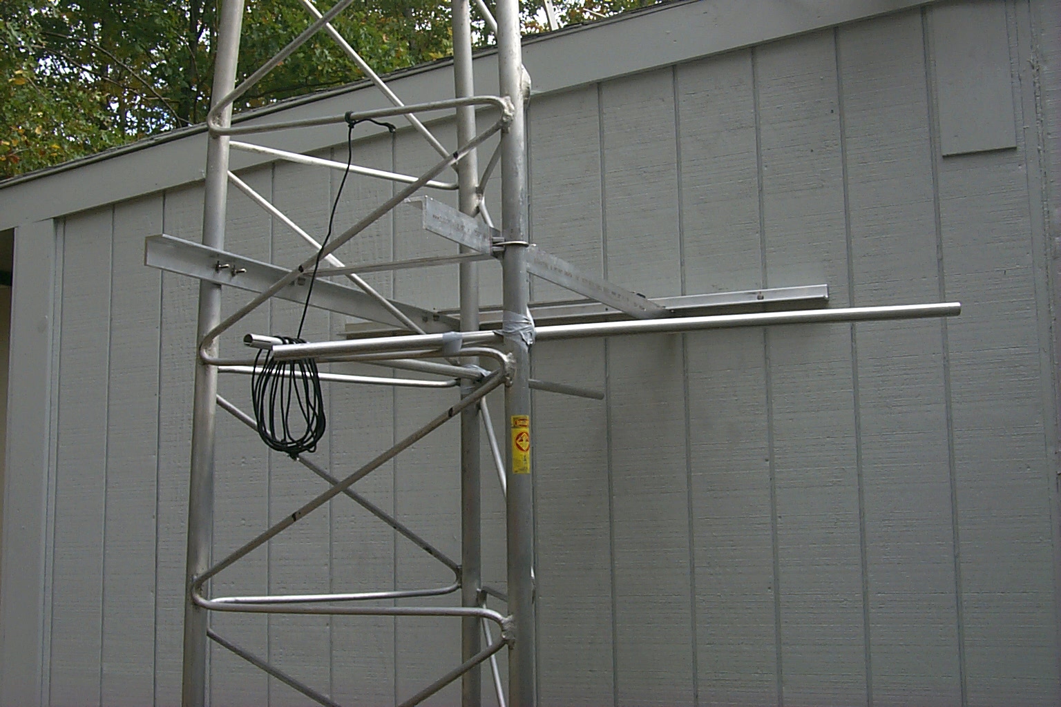
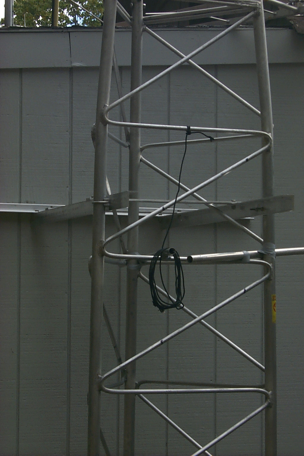
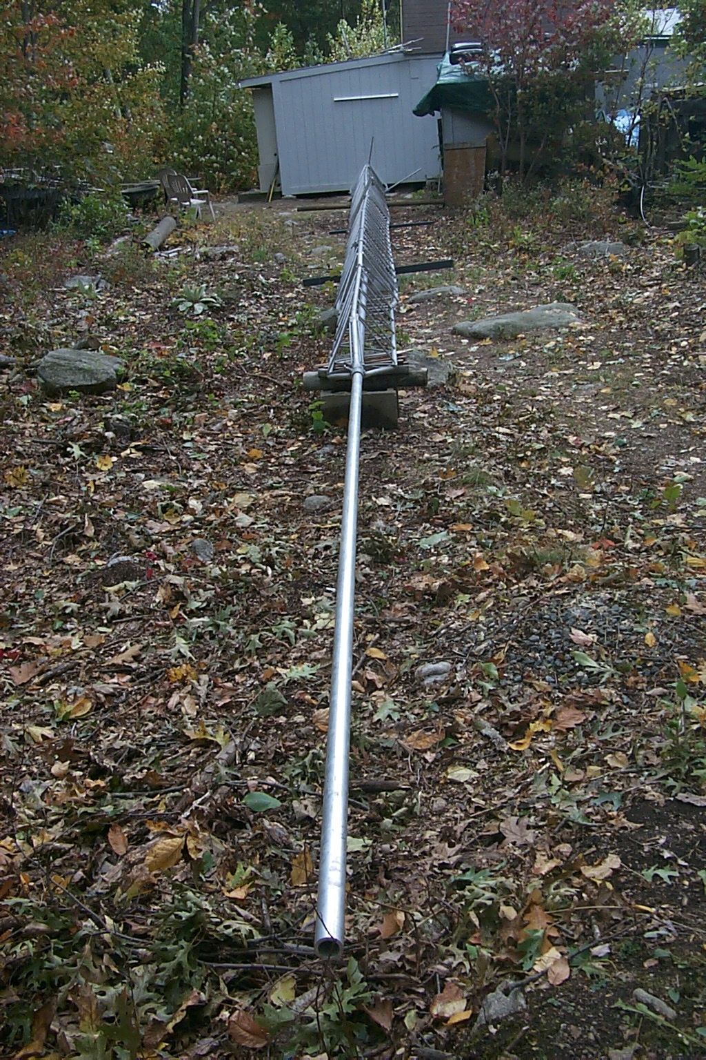
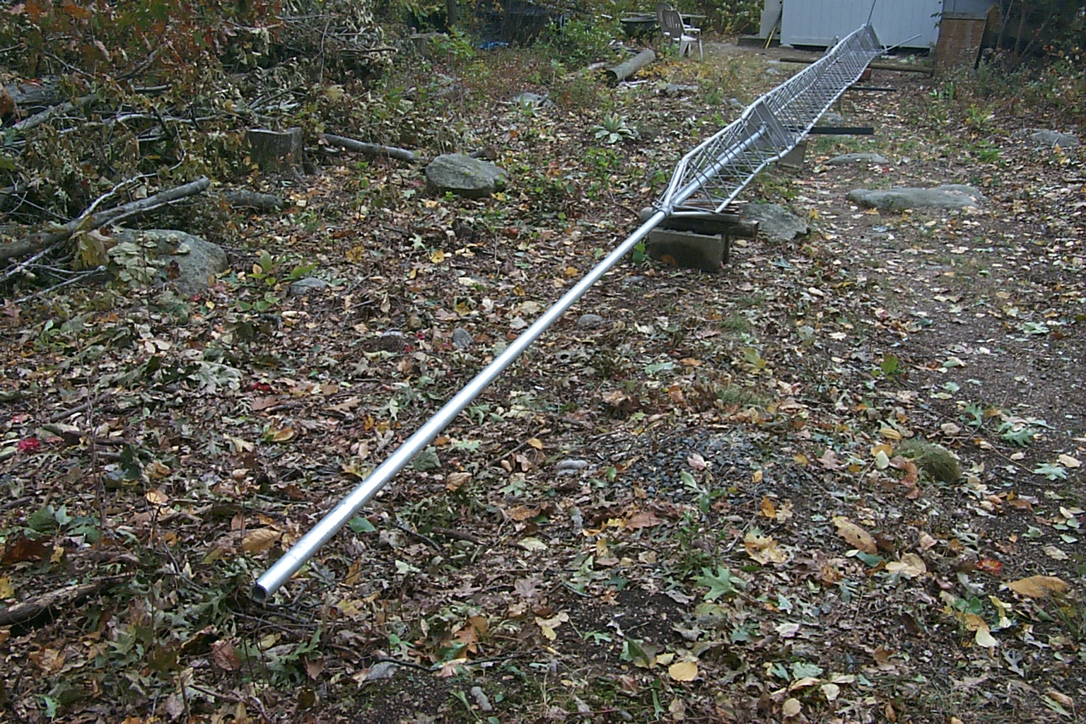
Monday morning the weather was perfect and Dad & I got an early start. We mounted the new JAG 144-148 MHz seven element end mounted Yagi on the tower and cranked the tower up so we could fine tune the new "Thunder Boomer".
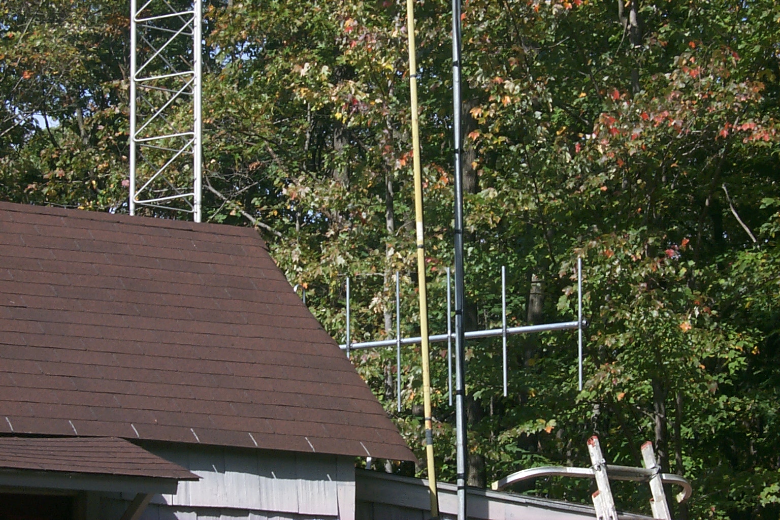
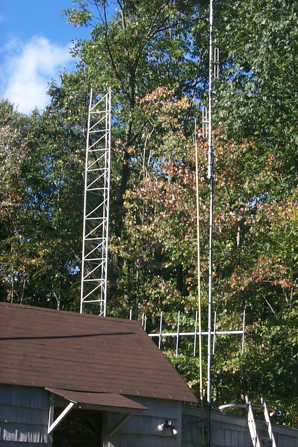
(click on images to enlarge)
We only four sections (half the tower) we are able to crank the tower up and down very easily which allowed us to work on the new JAG antenna down on the ground but crank it up for the VSWR sweeps. In the test location the antenna was only 12 feet off the ground so Dad was also able to stand on the repeater shed and make small adjustments to the various elements as well.
(click on images to enlarge)
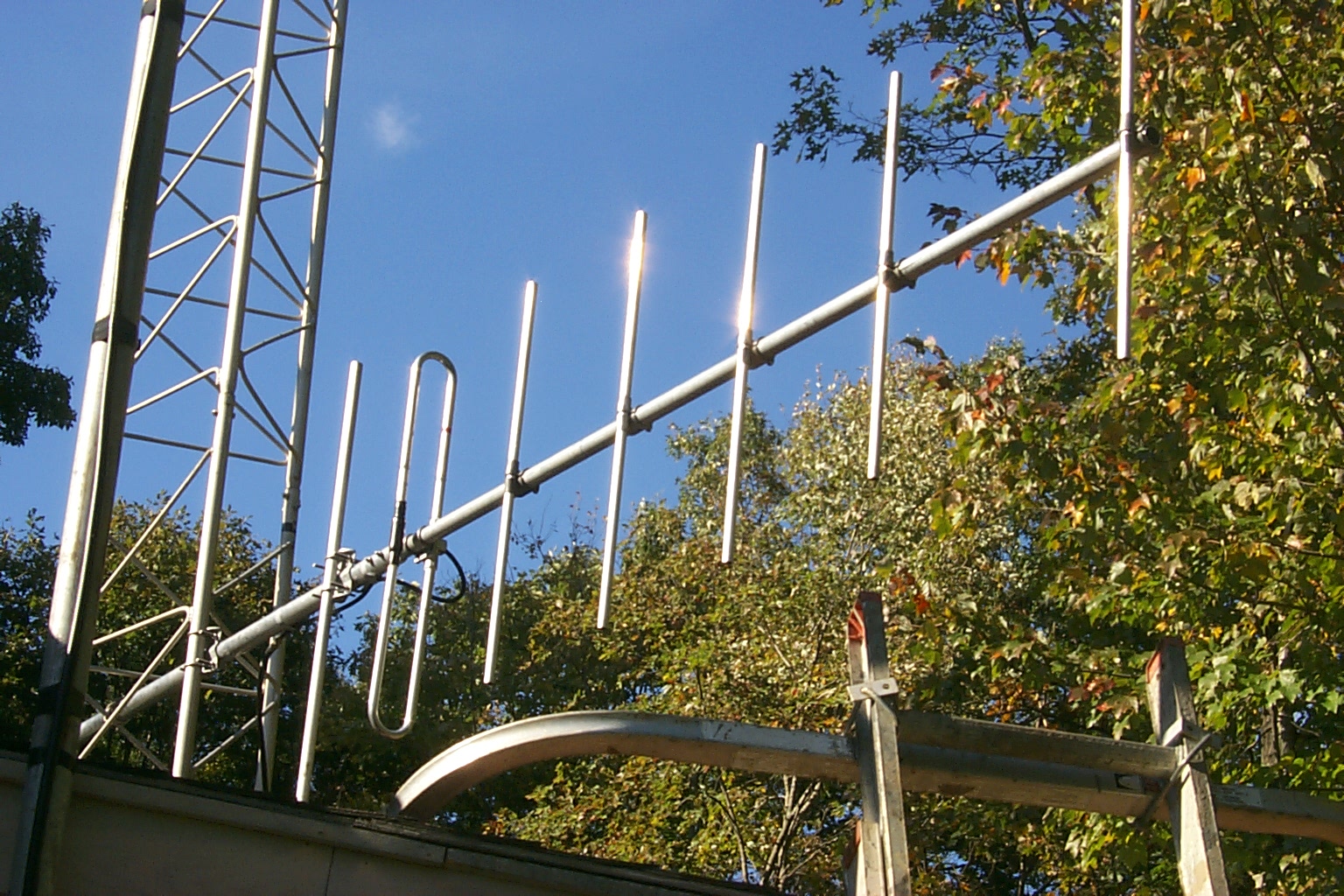
Working with Jag via email, we got the initial rough tuning by adjusting the spacing between Element No. 1 and Element No. 2 at the end of the boom and then dialed in the fine tuning matching the "Thunder Boomer" to my tower by adjusting the spacing between the Driven Element and the Reflector. In this series of VSWR Plots you can see the antenna moving towards the desired frequency as we made the adjustments.
(click on images to enlarge)
This is the last VSWR Sweep of the antenna in the test position; I will post the results of VSWR measurements when the antenna in mounted in the final position and the whole tower has been cranked back up.
| FREQ | Watts Fwd | Watts Rev | VSWR |
| 143.50 | 40 | 4.4 | 1.99 |
| 144.00 | 50 | 4.8 | 1.90 |
| 144.50 | 70 | 5 | 1.73 |
| 145.00 | 80 | 4 | 1.58 |
| 145.50 | 82 | 2.6 | 1.43 |
| 146.00 | 86 | 1.2 | 1.27 |
| 146.50 | 86 | 0.5 | 1.17 |
| 147.00 | 84 | 0.6 | 1.18 |
| 147.50 | 82 | 1.5 | 1.31 |
| 148.00 | 80 | 3 | 1.48 |
| 148.50 | 80 | 5 | 1.67 |
Tuesday "All Day" October 12th
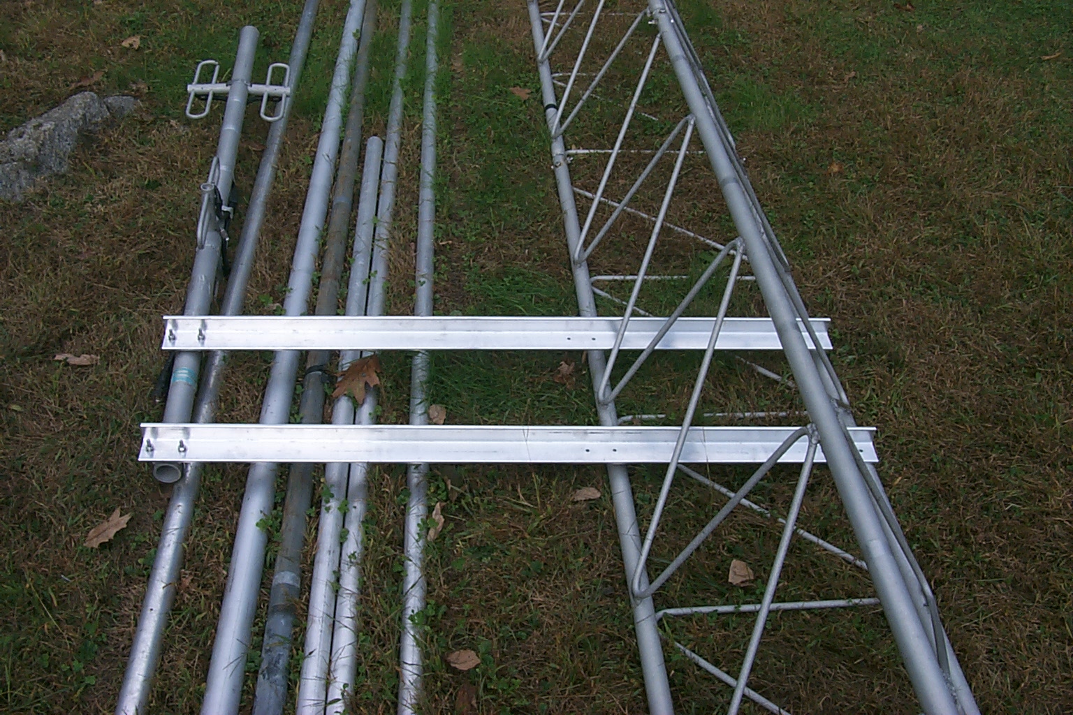
Mounting the mounts / antenna stand-offs
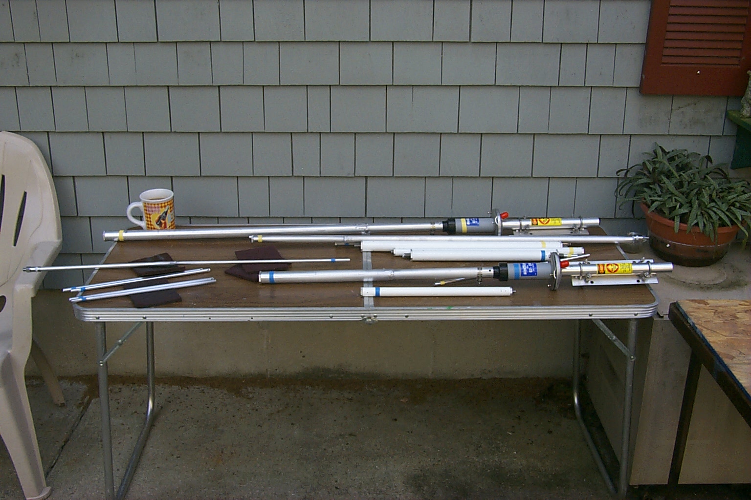
Today we got a late start as I had anticipated rain and did not set the alarm clock. After a quick run down to Warwick Industrial Fastener to pick up some stainless steel nuts & bolts Dad and I got right to work finishing all the various mounts and antenna stand-off arms. All of the angle stock had been cut to size a few weeks ago so we just needed to measure the locations on the tower for correct spacing and drill the appropriate holes for the saddle clamps.
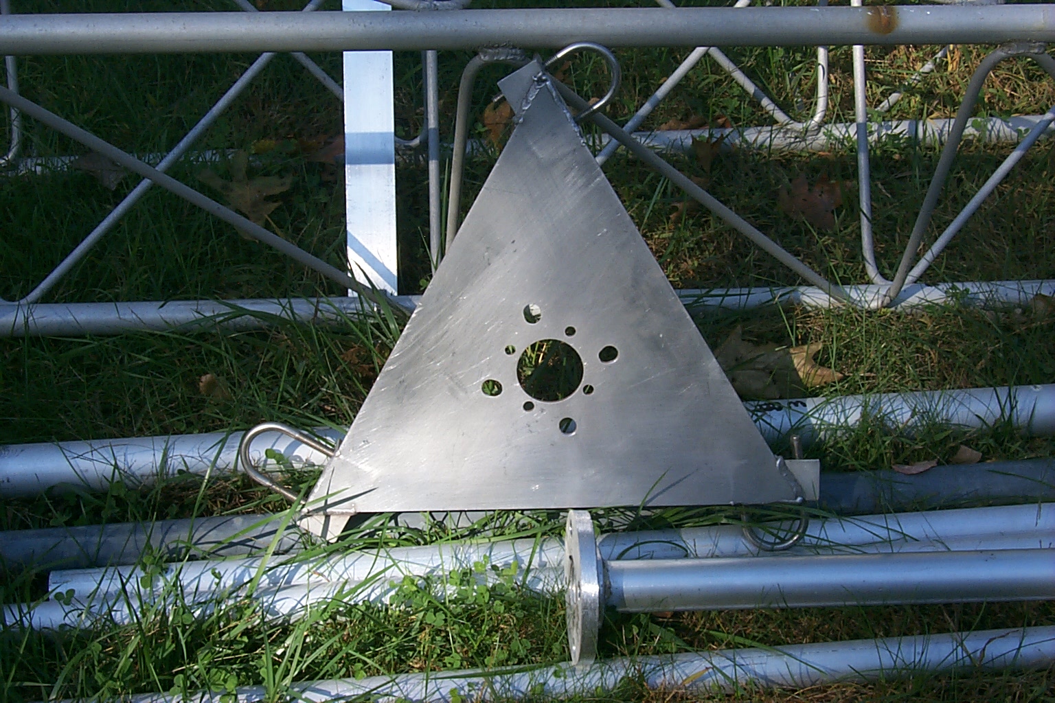
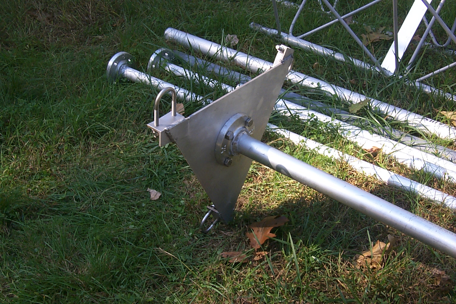
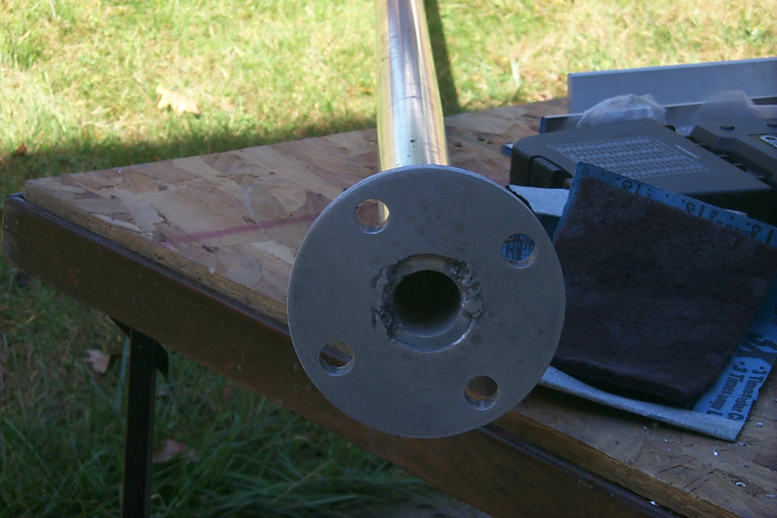
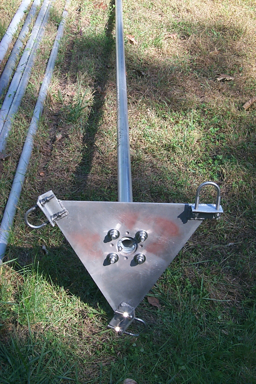
We started the with large rotor plate, cleaning and drilling new larger holes to mate up with the large aluminum flange that Scott had welded onto the bottom of the 24 foot main mast.
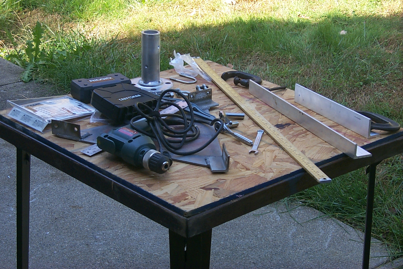
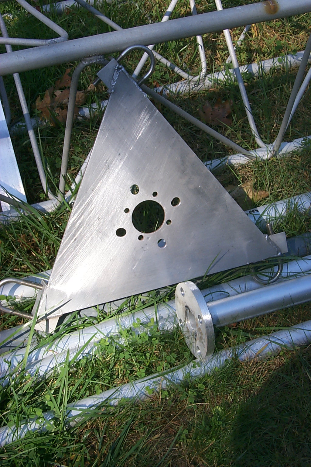
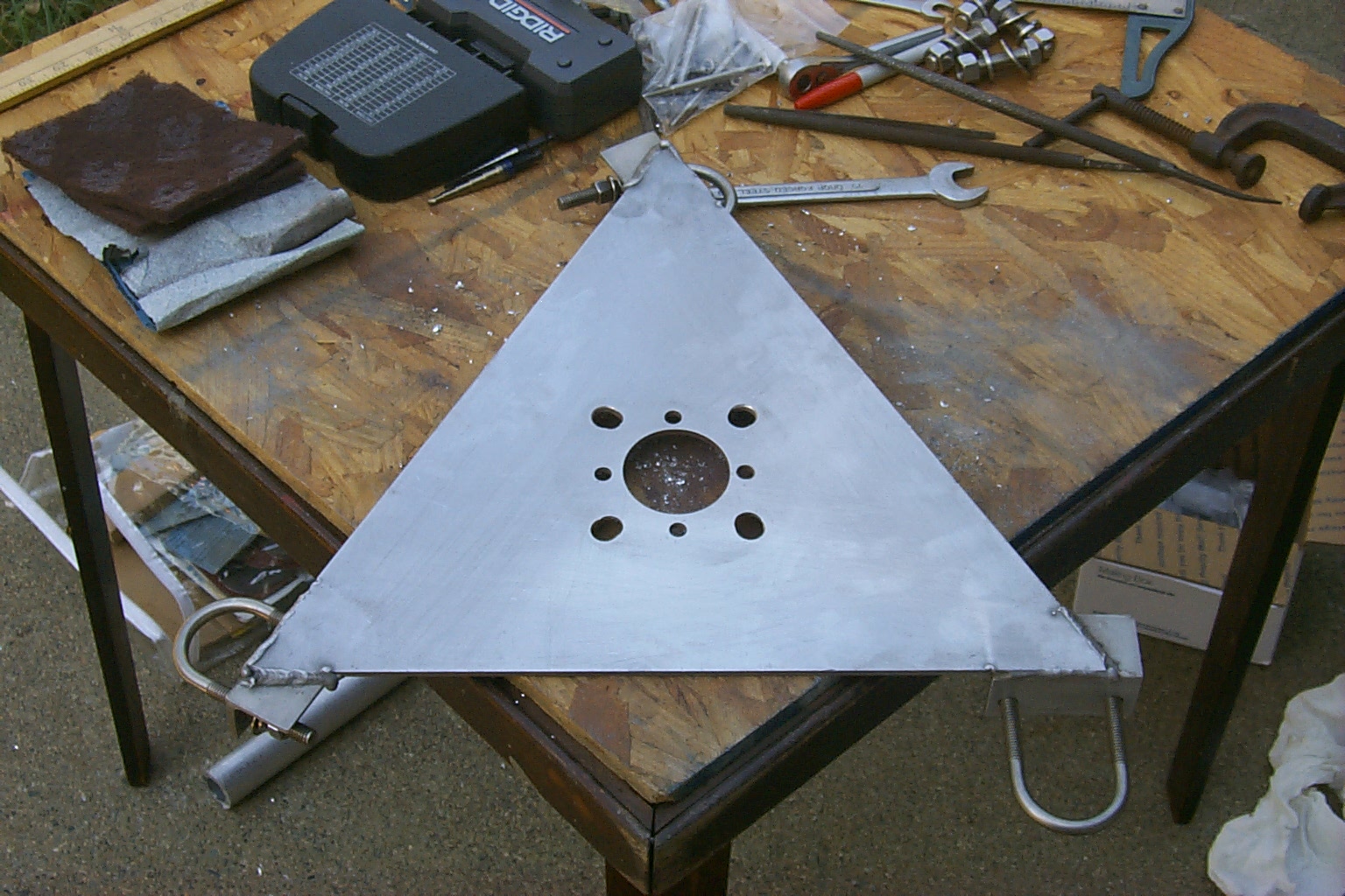
(click on images to enlarge)
Once we had cleaned the rotor plate and drilled all the holes I filed the bottom of the flange bracket and bolted the pieces together to make sure every fit correctly. These will be assembled in the top two sections of tower once we drag everything back into the woods.


(click on images to enlarge)
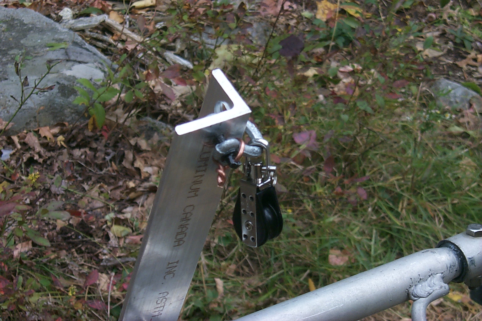
The next mount we finished was the doubled angle pieces that will be the back support for the JAG "Thunder Boomer". These two sections of angle stock clamp on both sides of the back two legs of the tower and will support two 2 inch saddle clamps. I have also added a small mount to hang a pulley for a flag halyard at this location.


(click on images to enlarge)
Then we just keep the assembly line going, I placed all the antennas and cut angle stock at there locations along side the tower, measured, drilled, and then test fit each antenna / stand-off arms.
These three photos show the stand-off and JAG 915-EX repeater antenna.


Here you can see the large stand-off arm for the G7-144 repeater antenna and the DB-402 GMRS repeater antenna.
(click on images to enlarge)
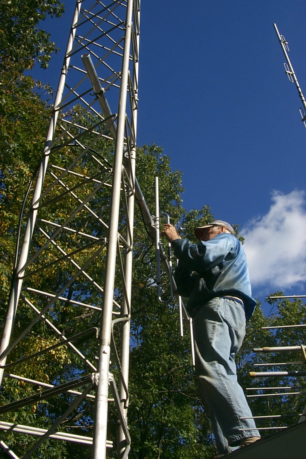
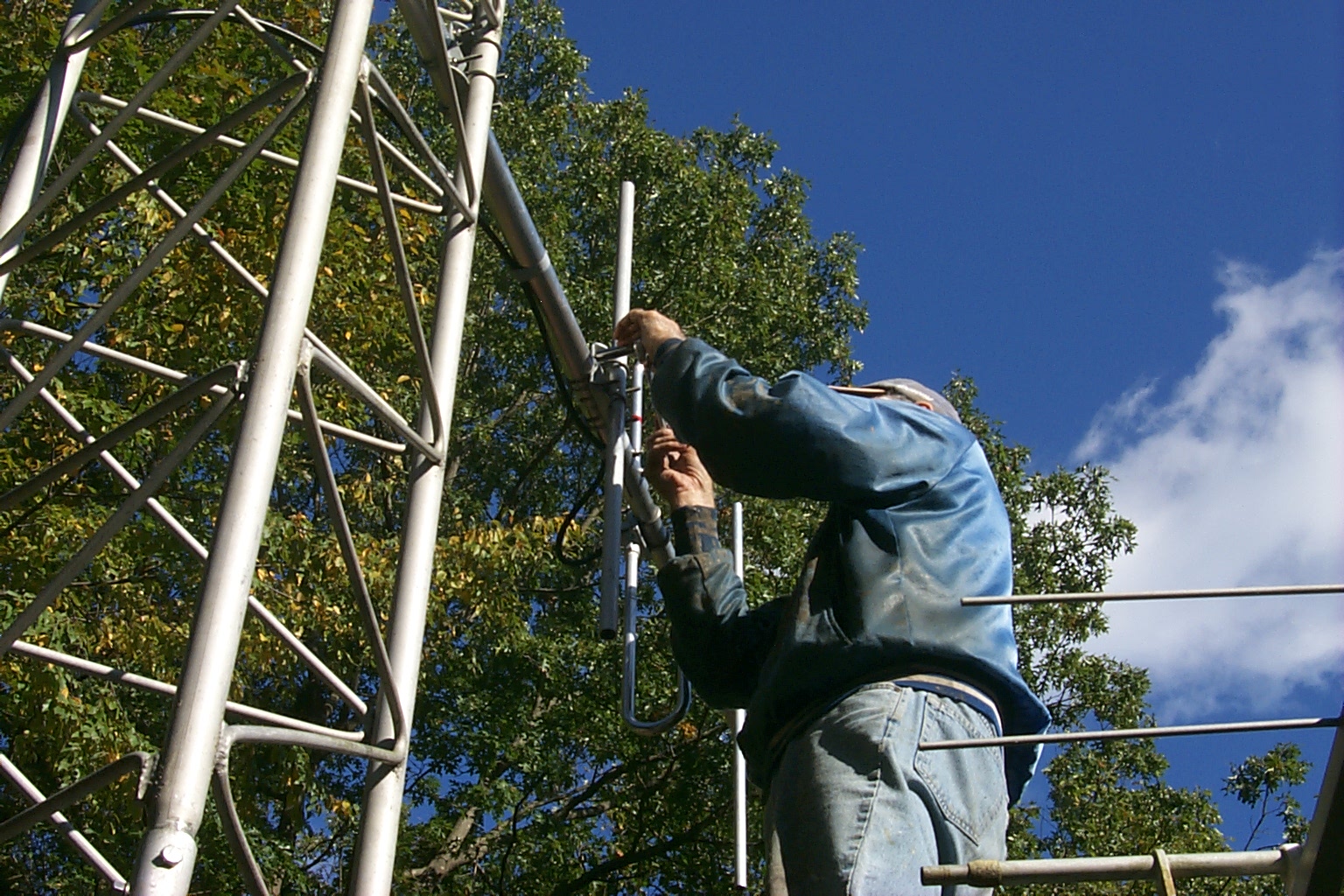
In these four photos you can see the first antenna to "officially" be installed on the tower as we get started mounting all the new antennas.
This is a tiny UHF 1/4 wave for a control link.


(click on images to enlarge)
If the weather holds we plan on building and tuning the G7-220 and G7-144 tomorrow!
Wednesday "All Day" October 13th
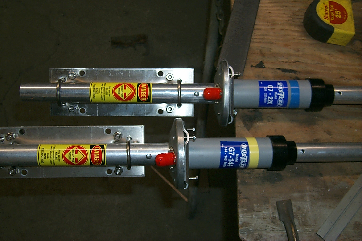
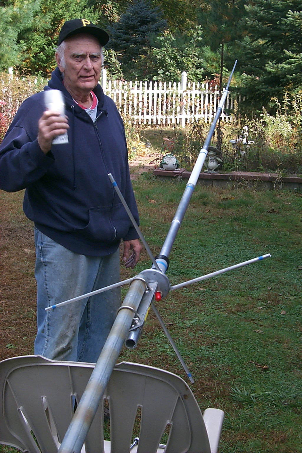
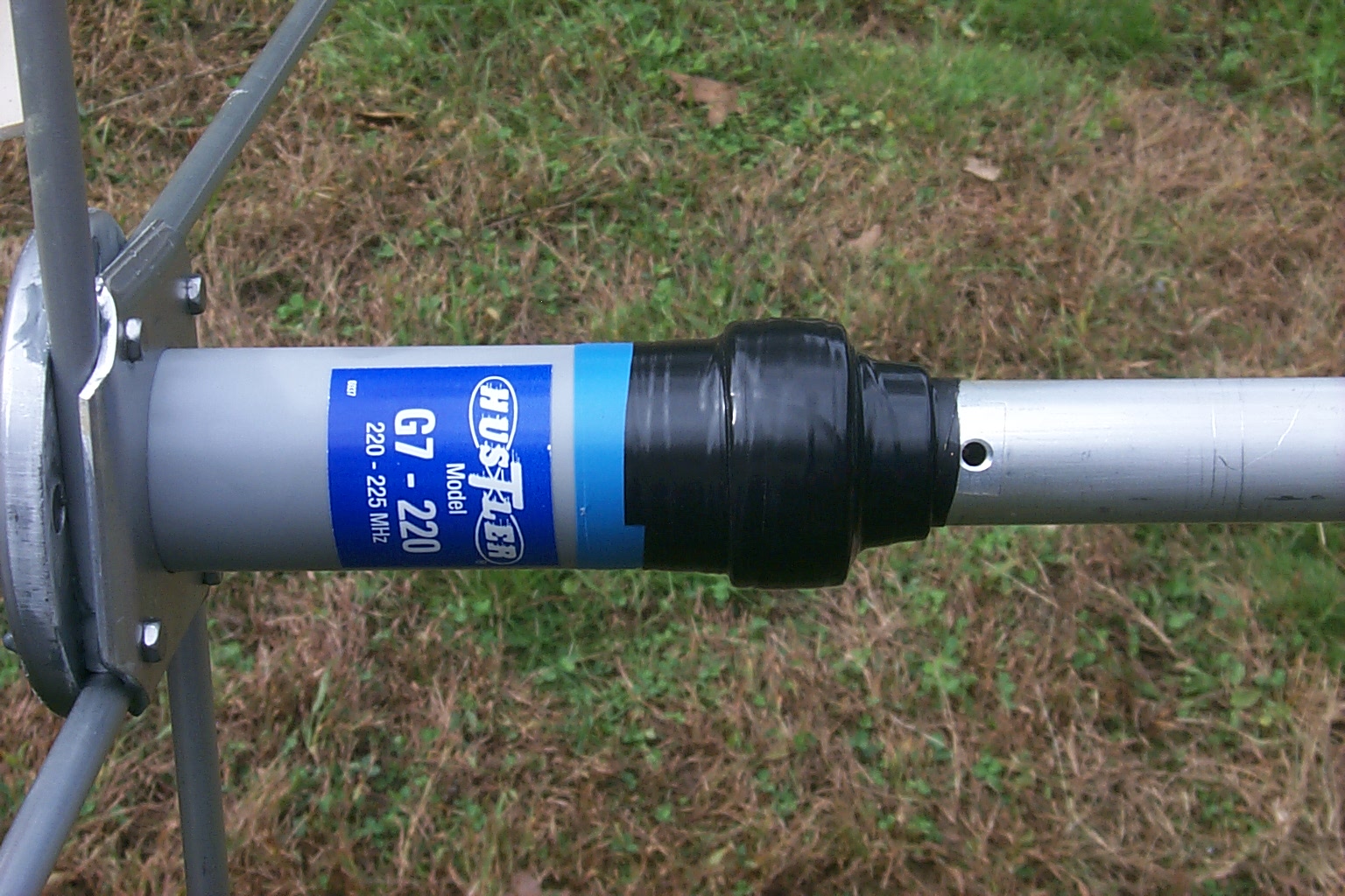
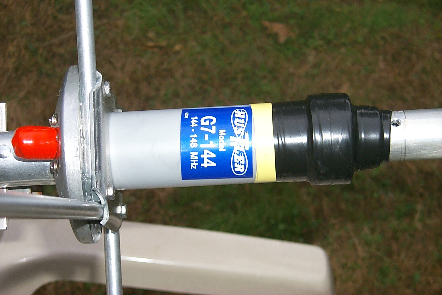
Tuning the Hustler G7-144 and G7-220
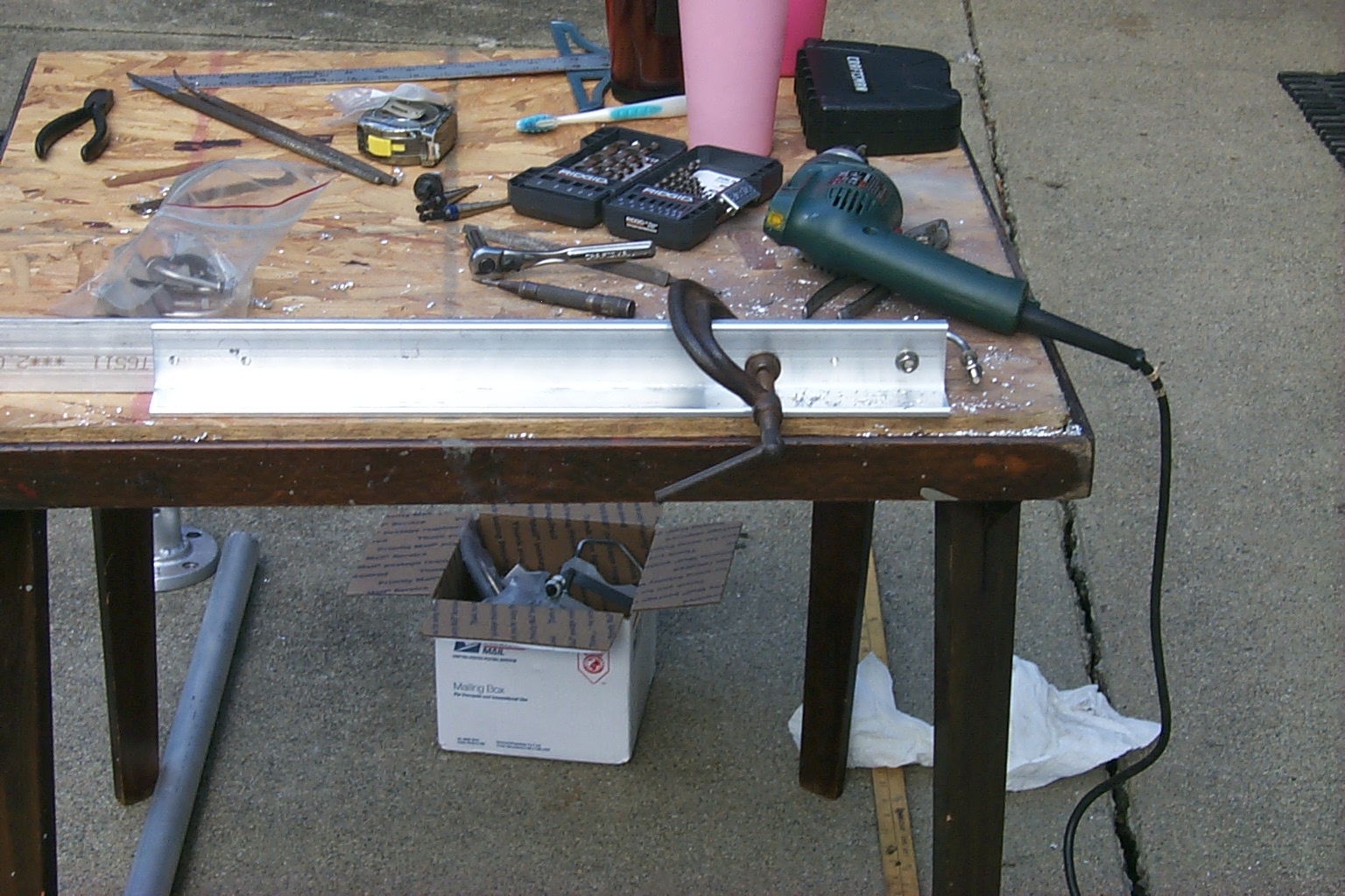
Up with the early birds today as we got started working by 8:00 AM this morning. It was a brisk 41 degrees when Dad and I started setting up the work bench, tools, and test gear to build and tune the G7-144 and G7-220 repeater antennas.
We follow the simple manufacture instructions and mounted each antenna on a 12 foot mast that we could easily stand up and down which made adjusting the different elements fairly easy. Both antennas tuned up well on the desired repeater frequencies.
The VSWR sweep and plot for the G7-144
| FREQ | Watts Fwd | Watts Rev | VSWR |
| 143.50 | 72 | 6.8 | 1.89 |
| 144.00 | 74 | 5.4 | 1.74 |
| 144.50 | 78 | 4 | 1.59 |
| 145.00 | 82 | 2.8 | 1.45 |
| 145.50 | 88 | 1.8 | 1.33 |
| 146.00 | 88 | 1 | 1.24 |
| 146.50 | 86 | 0.6 | 1.18 |
| 147.00 | 84 | 0.8 | 1.22 |
| 147.50 | 84 | 1.6 | 1.32 |
| 148.00 | 82 | 3.2 | 1.49 |
| 148.50 | 82 | 5.4 | 1.69 |
The VSWR sweep and plot for the G7-220
| FREQ | Watts Fwd | Watts Rev | VSWR |
| 220.00 | 19 | 2.2 | 2.03 |
| 220.50 | 20 | 1.8 | 1.86 |
| 221.00 | 20 | 1.4 | 1.72 |
| 221.50 | 22 | 1.1 | 1.58 |
| 222.00 | 22 | 0.75 | 1.45 |
| 222.50 | 24 | 0.5 | 1.34 |
| 223.00 | 24 | 0.25 | 1.23 |
| 223.50 | 25 | 0.09 | 1.13 |
| 224.00 | 25 | 0.004 | 1.03 |
| 224.50 | 24 | 0.048 | 1.09 |
| 225.00 | 24 | 0.055 | 1.10 |
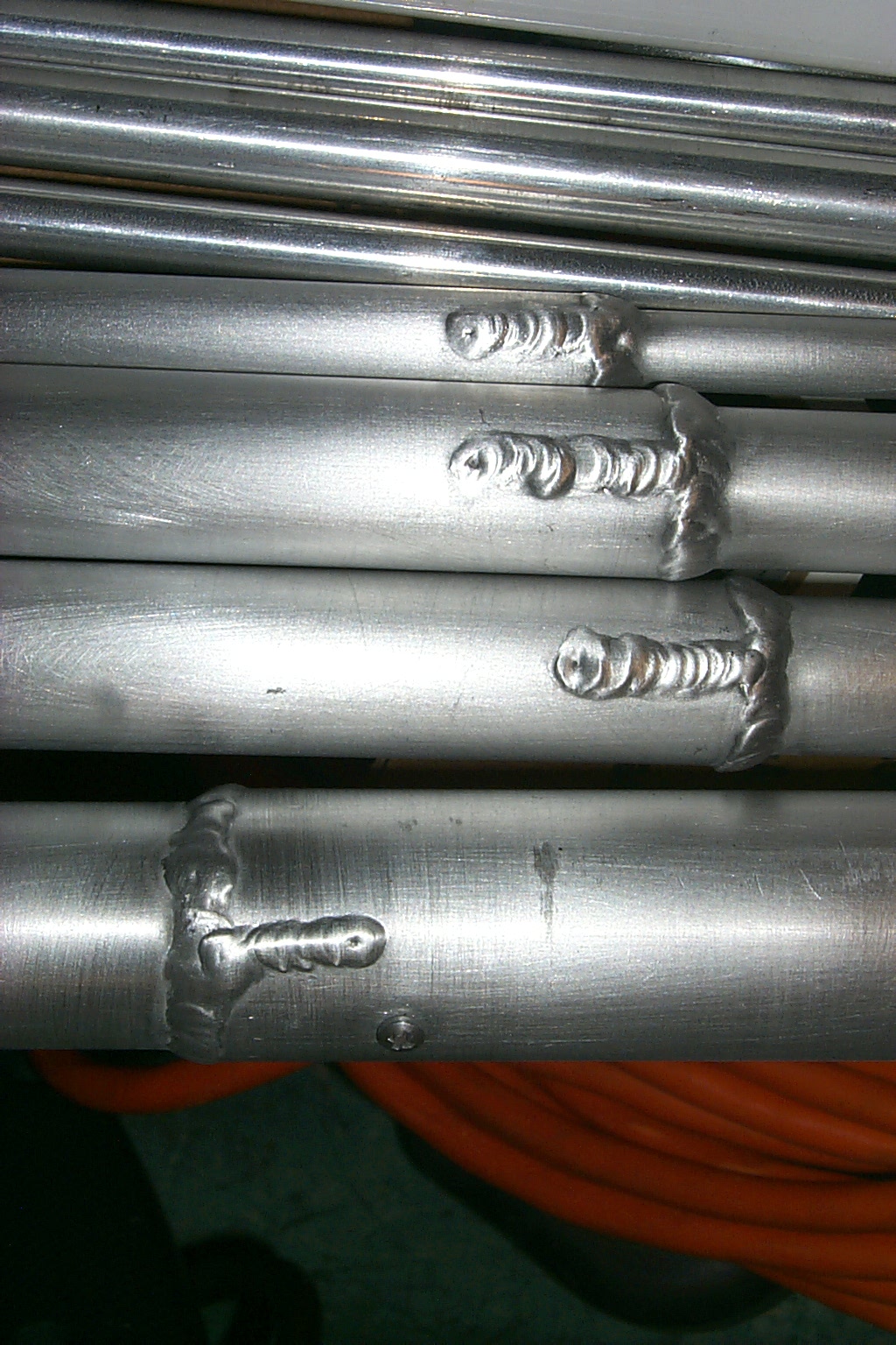
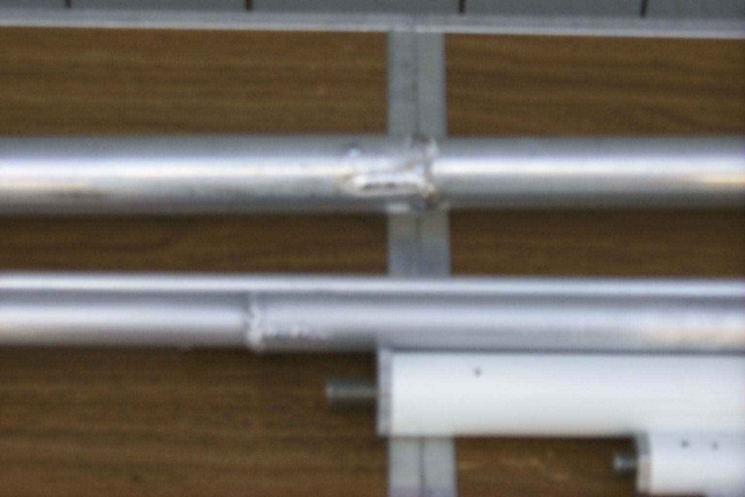
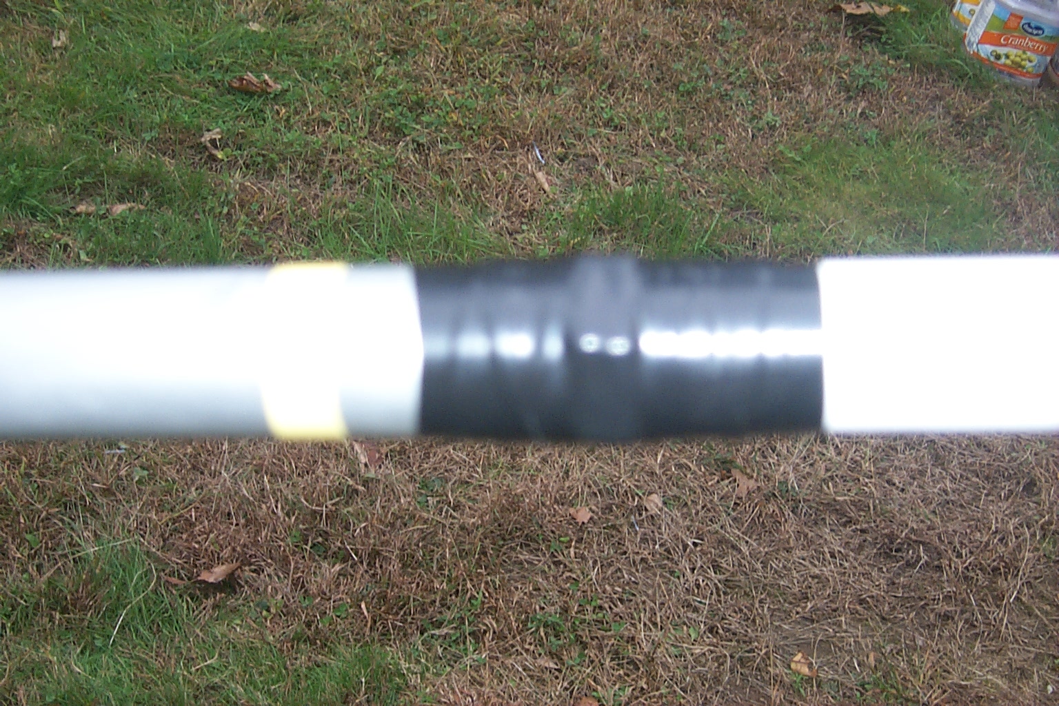
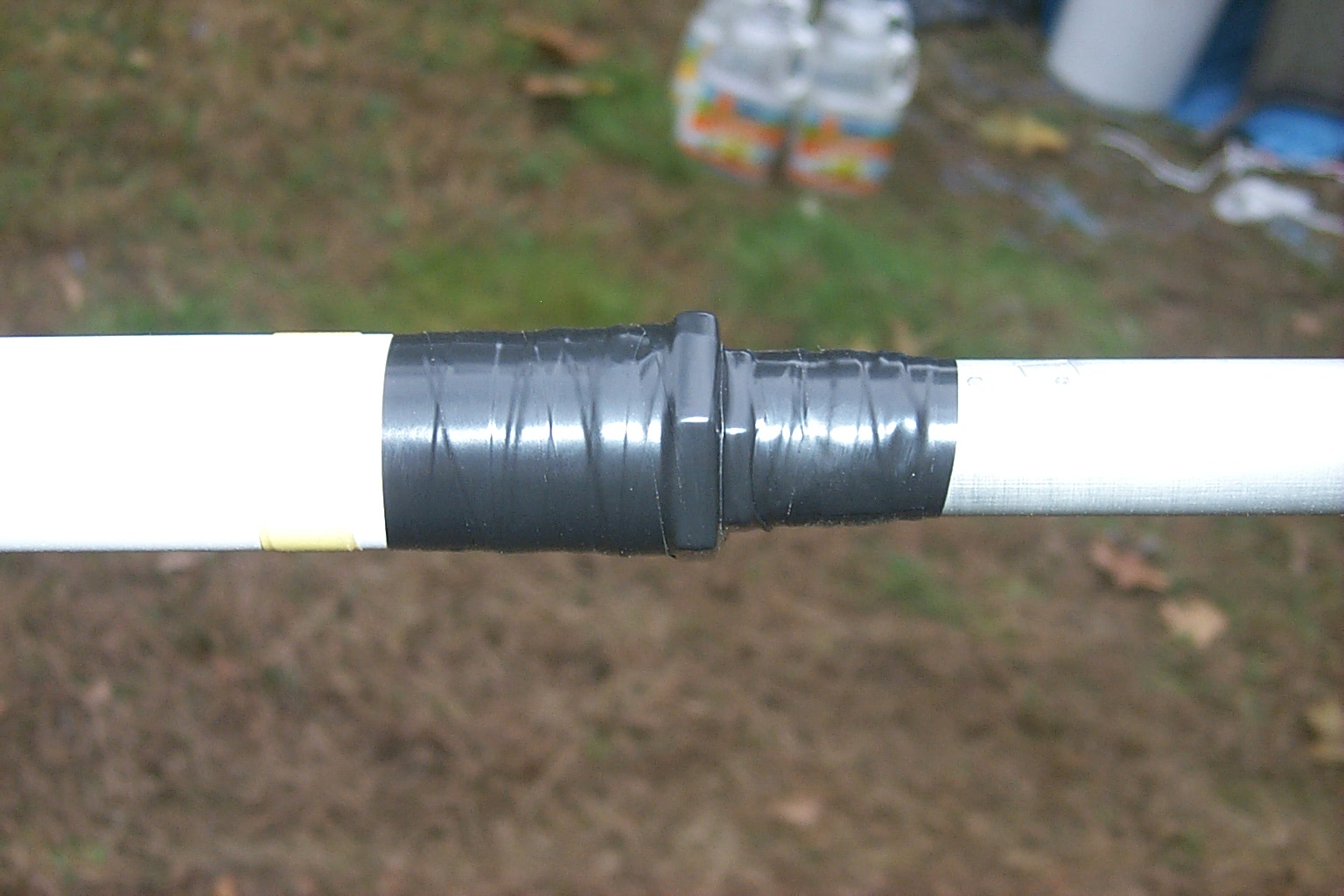
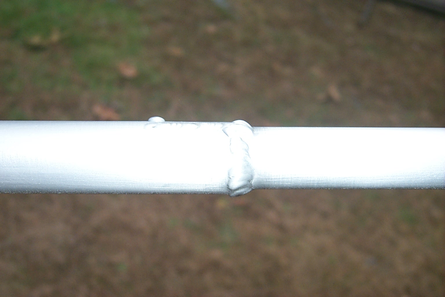
Once we had the antennas tuned where I wanted them I drilled a small hole at each adjustable joint and secured them with a small aluminum screw. Then it was off to see my brother-in-law Scott so he could weld all the adjustable joints for me. These antennas should last many years.

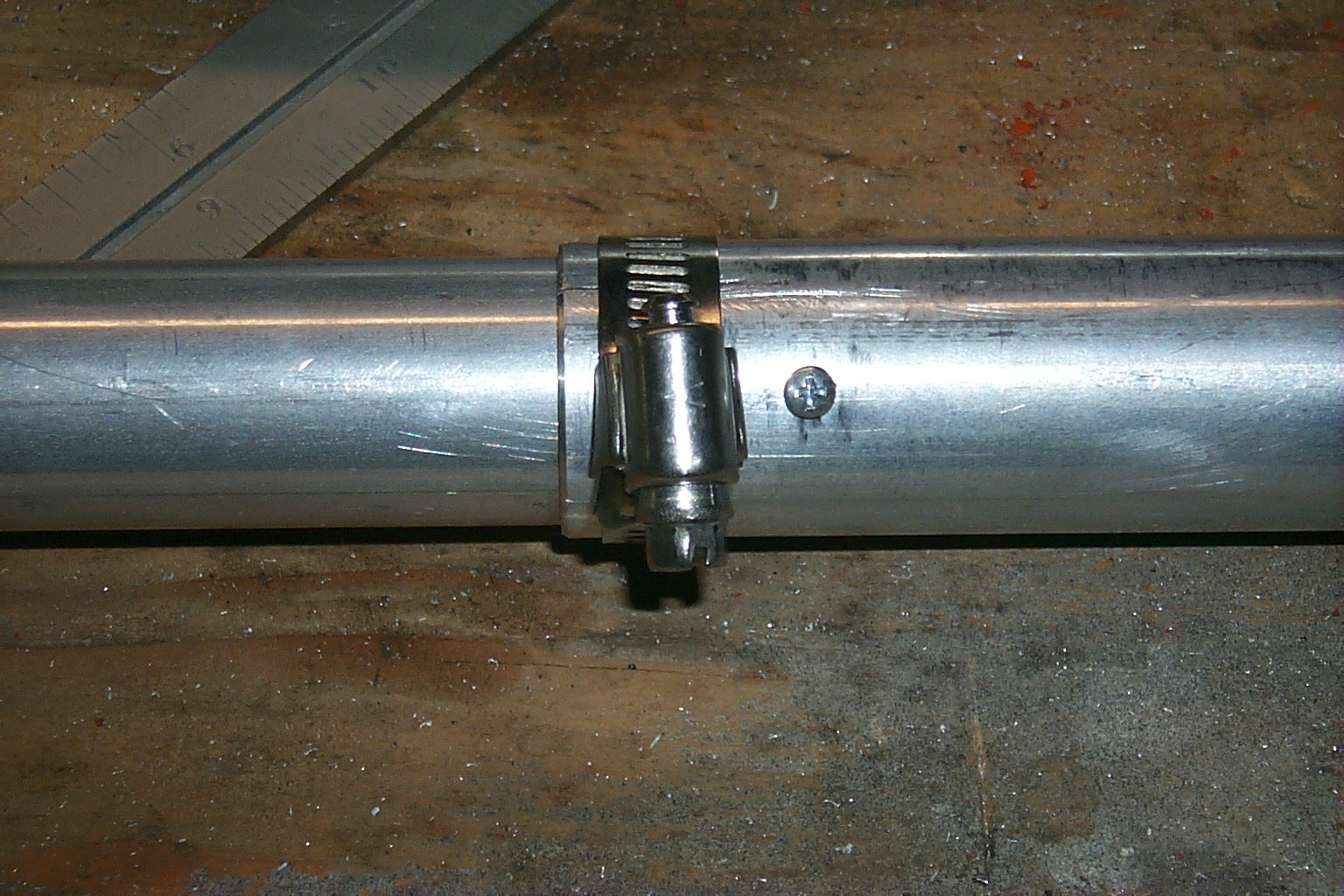

(click on images to enlarge)


(click on images to enlarge)


(click on images to enlarge)
If the weather holds we should be able to clean, assemble, and weather proof both antennas tomorrow. Then if time allows we will start mounting all the new antennas on the tower...
The "end game" has begun!
Thursday "Marathon Session" October 14th
Final Assembly - G7-144 and G7-220
Dad and I were up early again today and pushed hard to try and get as much work done as possible before the bad weather settles in later tonight and the next few days. We worked approx ten hours today completing the final assembly on both the G7-144 and G7-220 antennas.

(click on images to enlarge)
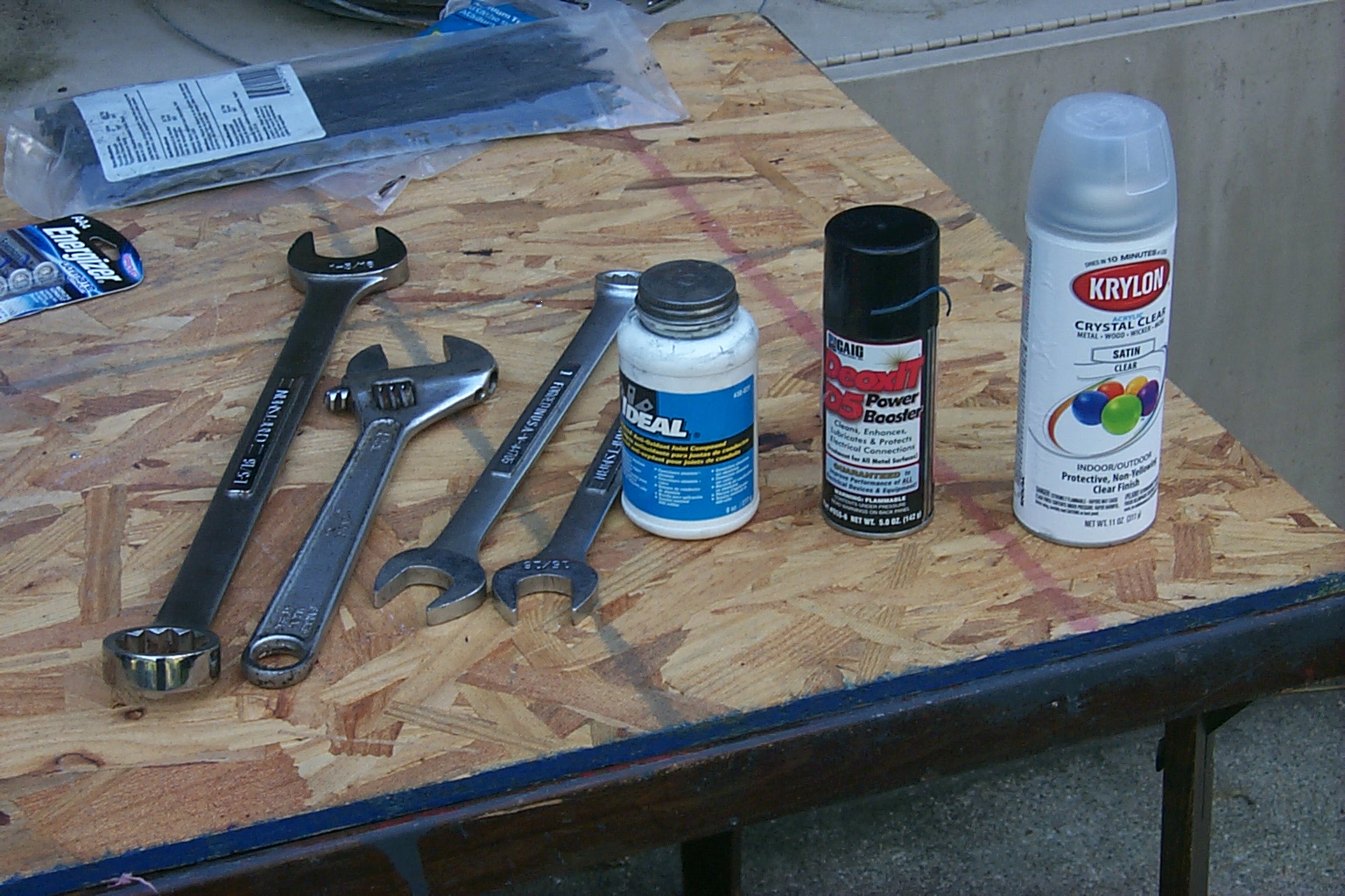
Both antennas got one last cleaning, all of the joins were coated with anti-oxidization goop, bolted together, and then received two applications of clear coat. After the clear coat was dry we weather proofed the joins with rubber stretch tape and then vinyl tape.


(click on images to enlarge)
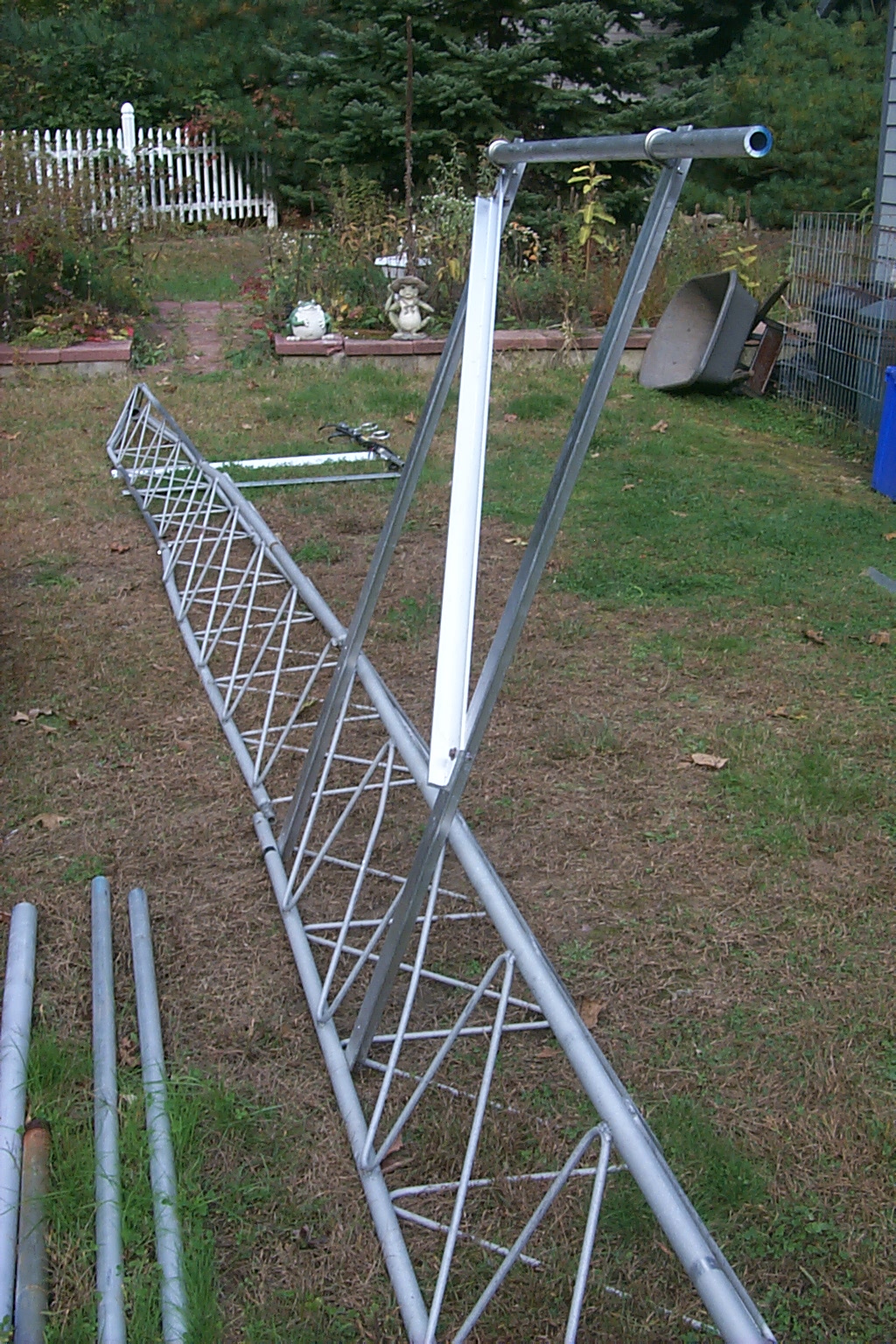
Building the Ice Bridge - Phase One
In between the antenna assembly steps, while the clear coat was drying, we cranked up the bottom two sections of tower and fabricated the frame for the ice bridge. This will support the ten runs of hard-line from the tower to the repeater shed and also protect the hard-line from falling ice.


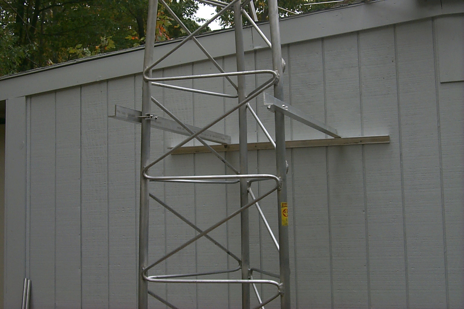

(click on images to enlarge)
We worked until the sun went down and did not get the tower sections assembled but that will be the next step once the weather breaks in a few days...
... To Be Continued
 Saturday "Another Marathon Session" October 16th
Final Assembly - Ice Bridge and Tower Sections
After a day of bad weather we got right back to work early Saturday morning finishing the ice bridge / hard-line support from the tower to the repeater shed. I shifted gears in mid fabrication and moved the two long support brackets inboard of the tower legs and also changed from the original plain of using threaded rod to using 1/4" thick by 2 " wide aluminum flat stock for the cross pieces.


(click
on images to enlarge)
This will allow me to use the Andrew hard-line cable clamps.
(click on images to enlarge)
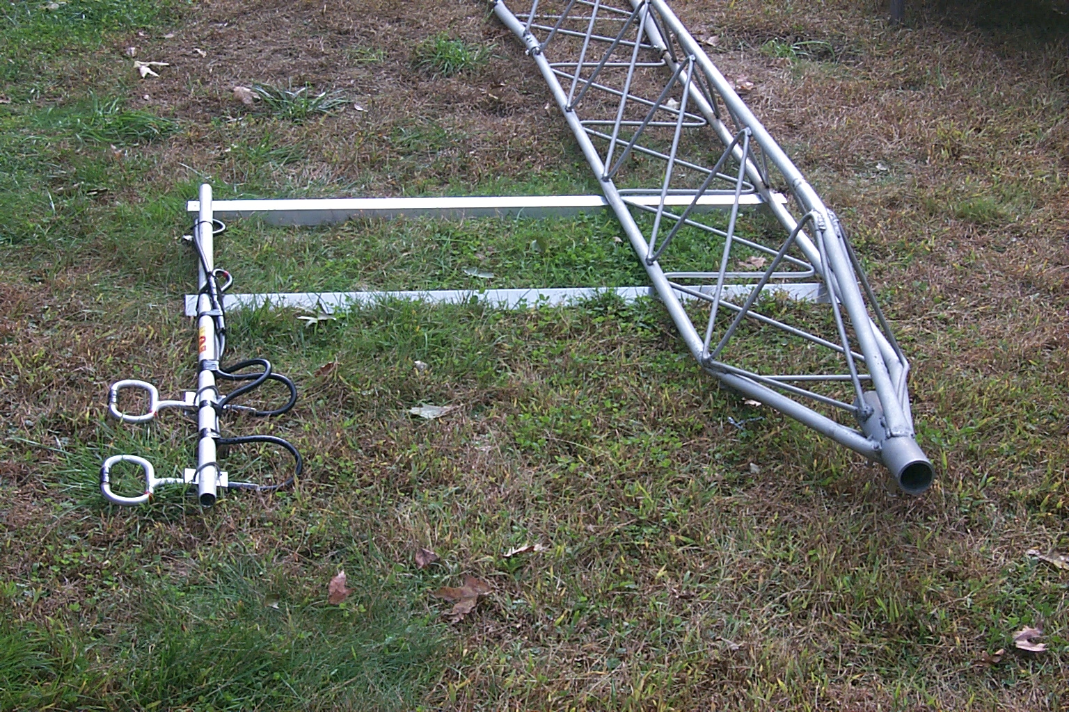
Once the supports for the ice bridge were completed we removed it from the tower / shed and dropped the tower back down onto the ground so we could assemble all the tower sections.


(click on images to enlarge)
Each section was positioned, anti-oxidization goop was applied, then we slid the sections of tower together and bolted them into place...
(click on images to enlarge)
Then there was just a lot of the same, over and over! LOL
When we finished with the top section of tower we installed the 24 foot section of mast and the rotor plate.

(click on images to enlarge)


(click
on images to enlarge)
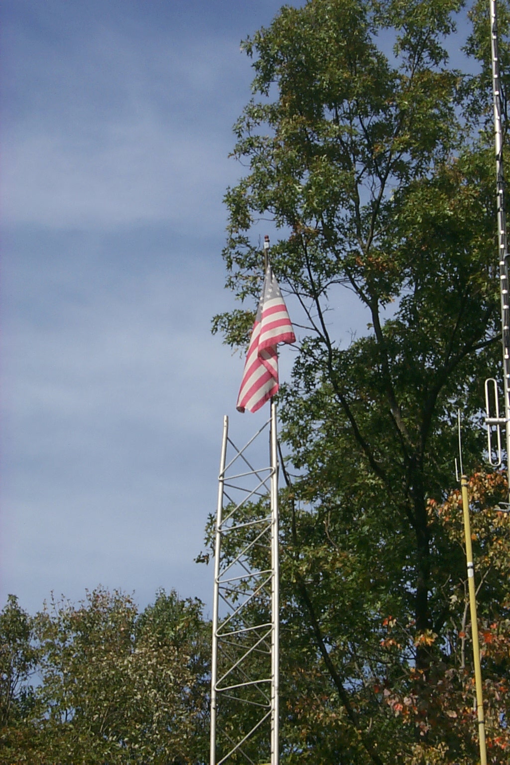
I also installed the new stainless steel pulley for the flag halyard and use a small piece of the original center conductor from the old Belden 9913 coax to lock the shackle that hold the pulley in place!
(click on images to enlarge)
The tower is completely assembled now and tomorrow, if I am able to work (or even MOVE for that matter), we will start installing all the new antennas!

(click on images to enlarge)
Back to Tower History Home Page
North 80 Foot Repeater Tower Main Page
East 38 Foot Repeater Tower - West 48 Foot VHF / UHF Tower
Return to the KA1RCI Repeater Network Home Page
This page was last updated on
11/07/2010 and it has been viewed times.
Send mail to [email protected] with questions or comments about this web site.
Copyright 1995-2010 Steven M Hodell
Copyright in these pages, in the screens displaying the pages and in the information, materials and other content contained in this web site is owned by Steven M Hodell unless other wise indicated and is protected by U.S. and international copyright laws and treaties. The information, materials and other content of this web site may not be copied, displayed, distributed, downloaded, licensed, modified, published, reposted, reproduced, reused, sold, transmitted, used to create a derivative work, or otherwise used for public or commercial purposes without express written consent.